Project - 2 - Meshing on the suspension Assembly
OBJECTIVE:
To clean the geometry of the component, extract the mid surface and mesh the component and provide suitable connectors to the component and satisfy the given quality criteria.
PROCEDURE:
Import the Rear wheel assembly file to ANSA and Using the Checks-geometry cleanup the component.
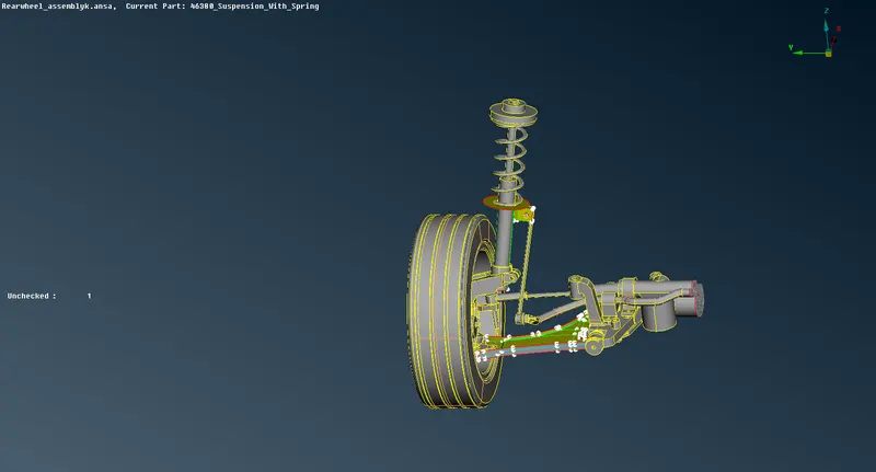
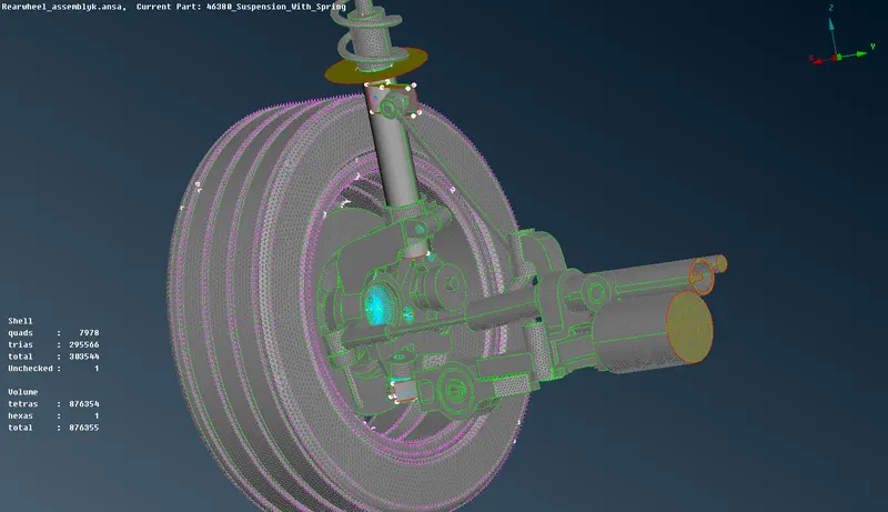
Some Geometry errors can be automatically cleaned up by right clicking and select Fis. Although some error might require manual cleanup and geometry checks and some are cleaned automatically.
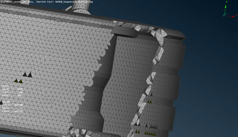
For Tyre and rim the perimetre and macros value is set and it is meshed with trias with given quality criteria using batchmesh or spotmesh.
Mesh generation is done using batchmesh and it automatically takes care of the geometry and topological cleanup.
After clearing all the off elements one can move onto volume meshing.
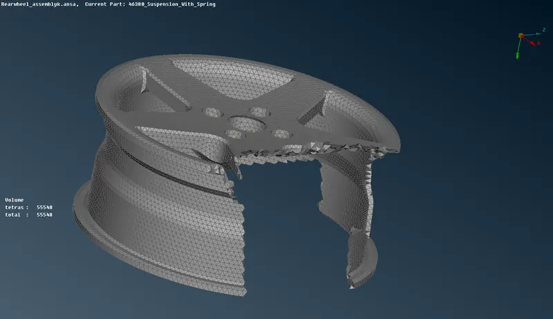
volume mesh is done in only closed volume and ANSA must recognize the visble component as a closed volume.
Under the volume mesh module, Define is used to define the volume of the component. A new Volume PID is cre
ated.
One can right click on it and slect remesh and select Tetra Fem or Tetra Rapid for the volume meshing.
MIDSURACE
For some parts Casting option is used to generate midsurface and mesh the component.
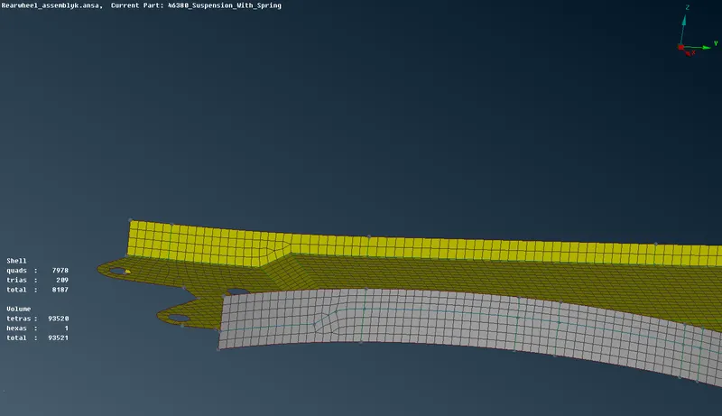
After assigning the given quality criteria and thickness with casting option the part is meshed.
For other parts with uniform thickness midsurface is created and using batchmesh, they are meshed.
The off elements are cleared and then using define option the volume is defined and meshed using tetra FEM or Tetra rapid.
CONNECTIONS:
After the component is cleaned up and meshed they are connected using spot weld, Seam weld, Bolts, RBE2 from the nastran deck.
For bolt connection create COG from the Topo deck and select points and create the points, after it is created go to mAssembly and select convert-3Dpoints-Bolt .
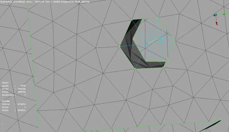
After it is converted go to Convertion manager and select the 3d point and select the two parts i,e assign p1 and p2 and if needed p3 and provide search distance and othercriteria and select apply and select realize.
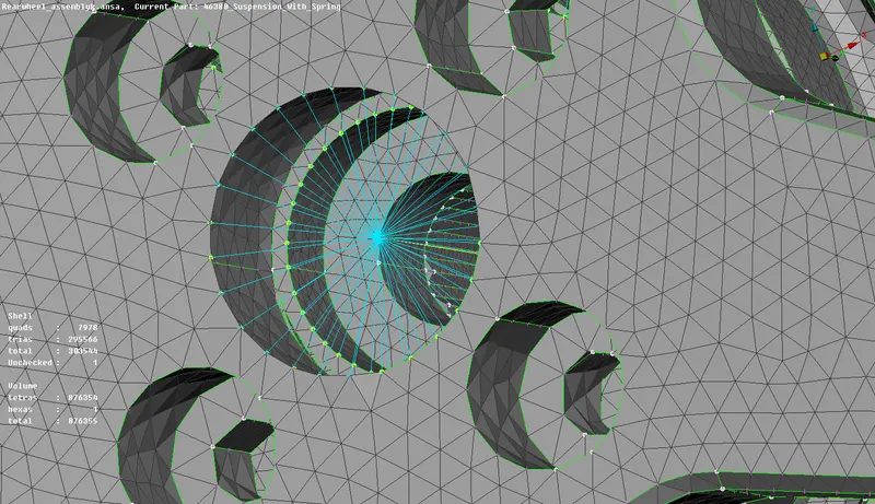
For Rbe 2 select nodes in the elements and select many nodes and create a RBE2 connection and we can also connect two master nodes by selecting RBE2 -two nodes and select two master nodes.
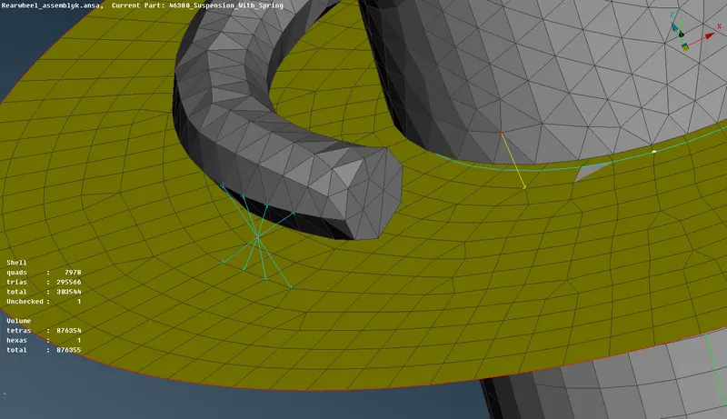
Spot weld is generally connected between two surfaces.
first create COG on the FE model.
Now convert it into 3d point using Assembly-Convert, Using conversion manager select spot weld and select type as RBE3-HEXA-RBE3
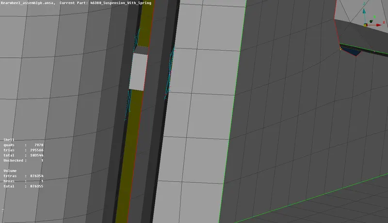
Assign necessary parts and search distance and select apply and select Realize.
TRANSFORM
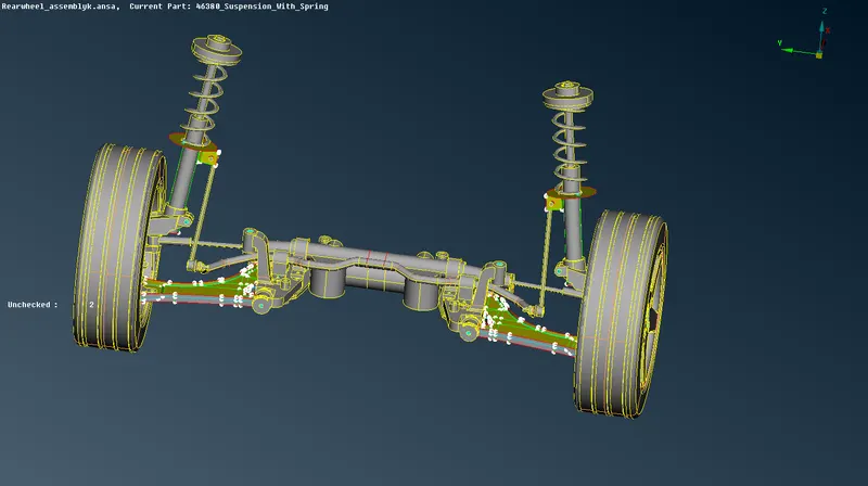
After completing all the surface and volume mesh we can use transform to create exact mirror of the component to the other side. use transform and select copy and and select all entities including the connections and select the points on the component as reference.
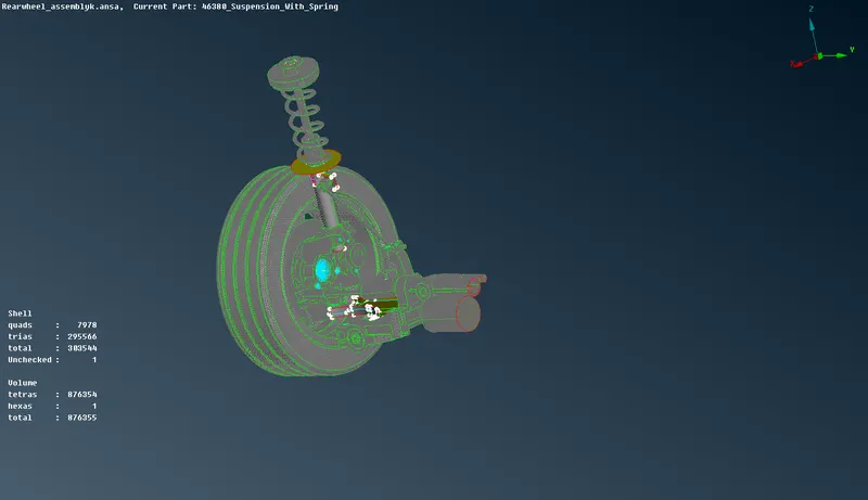
this will transform the components to the other side and we will have a component with symmetry.
RESULT:
In this component, the geometry has been cleaned up and the mid=surface has been extracted and meshing has been performed using different methods available in Ansa. All the connections has been deployed and the quality criteria has been satisfied and better mesh flow is acheived.
Google drive link:
https://drive.google.com/file/d/1IrsYD3A65qXLfzp6e9lh2xSJtmk_UtYK/view?usp=sharing