Project - 2 - FE Modelling of a Rear suspension Assembly using ANSA
AIM :
To Perform FE Modelling of an Automotive rear suspension assembly.
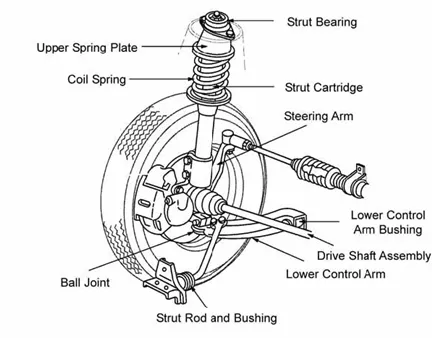
GIVEN DATA :
The given data are the inputs to work. Here the given data are,
- CAD model.
- Quality criteria.
- CAD MODEL: Here the given cad model is Rear suspension assembly of an automobile.
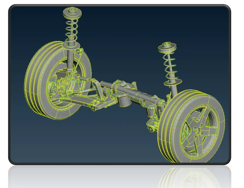
Figure 1. CAD model - Given data.
- QUALITY CRITERIA : Every product which is been produced will go through the set of quality check. If the quality check fails other steps like boundry condition & apllying loads will not be feasible, So for this reason the element quality check is performed. To identify the quality failure the quality criteria will be entered as an input data. The given quality criteria are shown in the below table. The elements should be maintained within the below given value. If the given quality value is not maintained there will be a failing in qulaity.
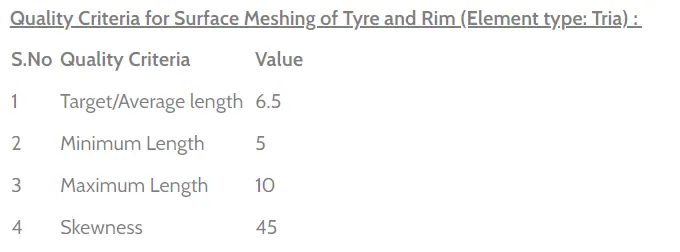
Figure 2. Quality criteria - Surface meshing for tyre and rim
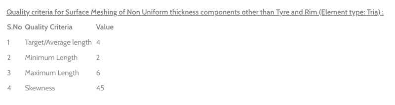
Figure 3. Quality criteria - Surface meshing for Non uniform thickness other than tyre and rim

Figure 4. Quality criteria - Volume meshing
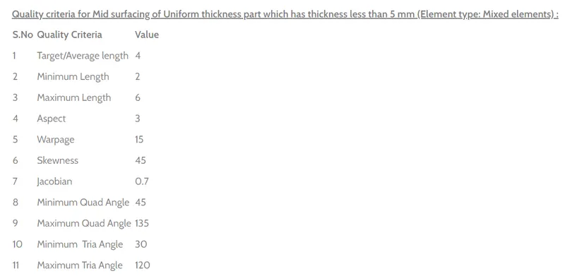
Figure 5. Quality criteria - For shell meshing of uniform thickness part
THEORY:
MESHING :
- Meshing - Automated net generated.
- A mesh is a network that is formed of cells & points. It can have almost any shape in any size & is used to solve partial differential equations. Each cell of the mesh represents an individual solution of the equation which, when combined for the whole network, result in a solution for entire mesh.
- FEM allowed for mixed types of mesh cells & unstructured meshes became feasible.
- 2D - Structural mesh.
- 3D - Unstructured as well as structured mesh.
Process of Meshing:
- Definite element size.
- Choose types of element.
- Shell mesh (2D - tria & quad)
- Various methods.
- Surface less meshing.
- Solid mesh (3D - tetrahedron, hexahedron, pyramid, wedge)
- Tetra mesh ( Unstructured mesh).
- Hexa mesh ( Structured mesh).
- Quality cruteria check.
- Remesh - Quality improvement.
ORTHO TRIA Vs TRIA ELEMENTS:
- Ortho tria capture the features more accurately than tria elements.
- Mostly, otho tria will be used in curved surfaces whereas trias will be used mostly in flat surfaces.
- Surface distortion can happen in the curved faces while we using normal trias, So to avoid those distortion we go with ortho tria elements for curved faces.
PROJECT METHODOLGY:
Methodology used in this project are as follow,
- Surface meshing is performed for modelling a tyre and rim component by considering the given quality criteria.
- Element type - Tria/orthotria
- Surface meshing is been performed for modelling a non uniform component other than tyre and rim parts.
- Element type - Tria/orthotria
- Solid mesh has been performed for the tria/ortho tria element used for modelling tyre & rim & non uniform component.
- Mid surface is extracted for modelling parts having uniform thickness and performed shell mesh considering quality criteria. Draw shell has been enabled to visualization the thickness of the parts.
- 1D element --> CBAR is used to model a suspension coil spring. To visualise the cross section of the spring line element cross section has to be enabled as solid.
PROCEDURE:
- Import the cad geometry - Input the given cad model. Here the given cad model is rear suspension assembly of an automobile.
Figure 6. Cad model (Imported)
- Perform Topology - In Topo module, Go to Faces ---> Topo ---> Select the model & middle click.
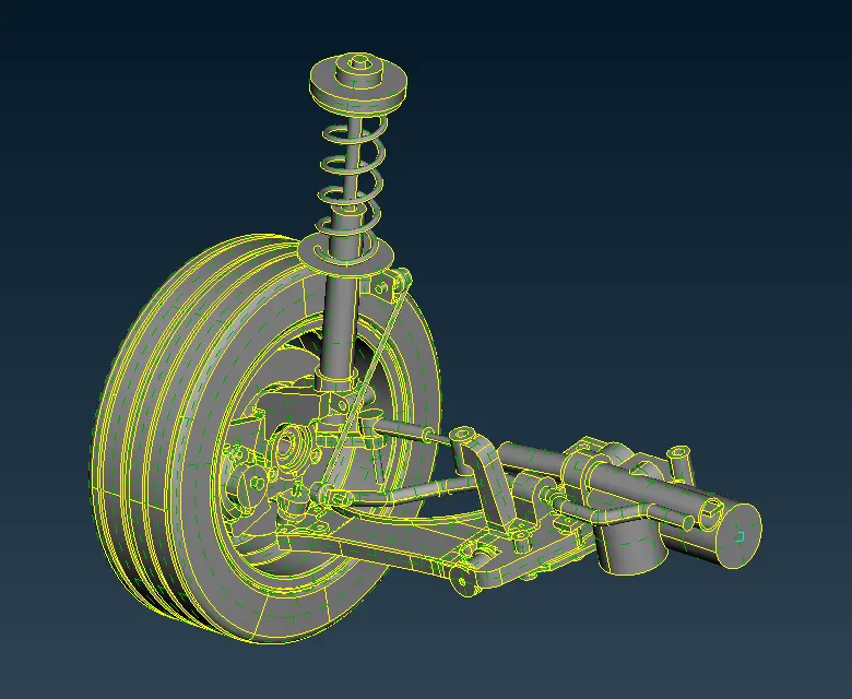
Figure 7. Topology.
- Geometry cleanup - To generate FEM we clean up the geometry. Surface patch up, creating new surfaces, eleminating of triple cons in unwanted area, converting single cons to double cons in necessary area are comes under geometry cleanup phase. ANSA has some option to rebuilt the surfaces for some extent. By using checks manager we will check the geometry & if the error shows fix those error manually or by using autofix.
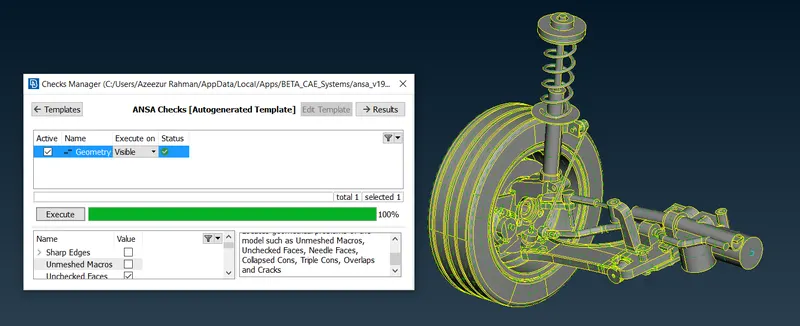
Figure 8. Geometry check
- Quality criteria - Every product which is been produced will go through the set of quality check. If quality check fails other steps like B/C & applying loads will not be feasible, So element quality check will be performed. The given quality criteria values been enterd in quality manager ( shortcut key : F11). These colours are customizable and can be seen while meshing if the elements are beign failed. These failed elements should be corrected and the elements should matches the quality criteria.
Here in tetra modelling, we have to consider only for minimum & max. length in shells criteria and to consider the tetcollapse in solids criteria
- Set mesh parameter - Mesh parameters is nothing but defining the meshing parameters. Once assiging the qulaity value mesh parameter has to be set.
- Since, it is a tetra modelling we should select for orthotria / tria elements.
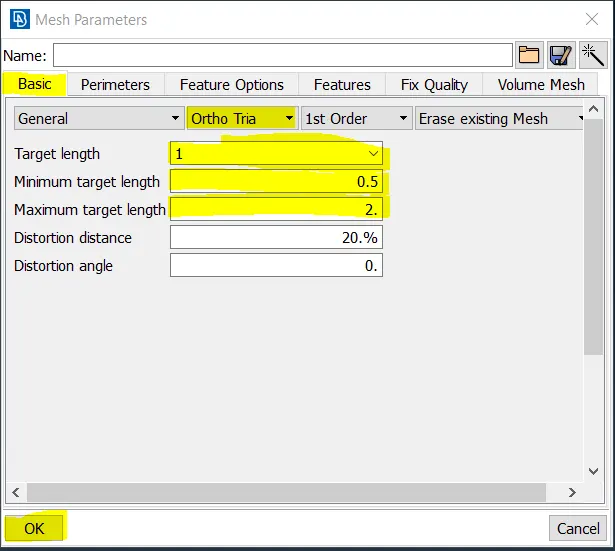
Figure 9. Mesh parameters setup
- Meshing - Automated net generated.
- Surface meshing is performed for modelling a tyre and rim component by considering the given quality criteria.
- Element type - Tria/orthotria
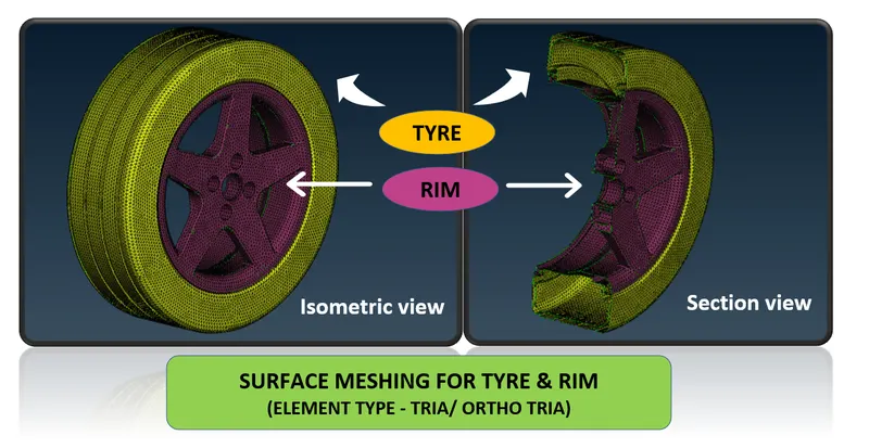
Figure 10. Surface meshing - TYRE & RIM
-
- Here, In section view we can see that after spot or mapped mesh there is a hollow space without meshed. Now the mesh should be achieved by getting to volume mesh module.
- Surface meshing is been performed for modelling a non uniform component other than tyre and rim parts.
- Element type - Tria/orthotria
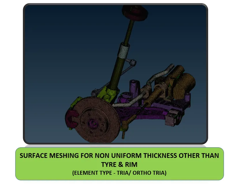
- Figure 11. Surface meshing - Non uniform thickness other than TYRE & RIM
- Solid mesh has been performed for the tria/ortho tria element used for modelling tyre & rim & non uniform component.
- Volume Mesh - we can see that after spot or mapped mesh there is a hollow space without meshed. Now the mesh should be achieved by getting to volume mesh module.
- After completing the tria mesh it should be converted to tetra mesh.
- Tetra mesh are the unstructured mesh where ANSA uses to generate tetra elements inside any component where the surface is meshed by trias/ortho tria elements.
- Before making to the tetra identify that the geometry has a closed volume.
- Now the volume mesh has been completed by eleminating tet collapse
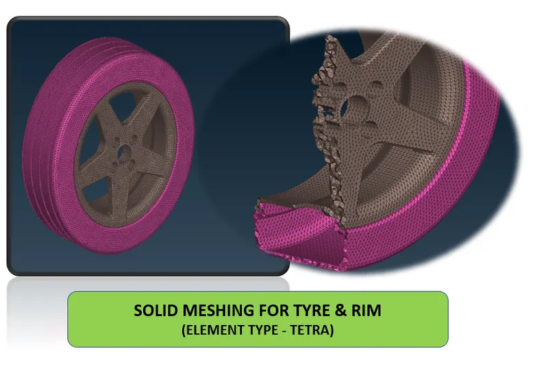
- Figure 12. Volume meshing - TYRE & RIM
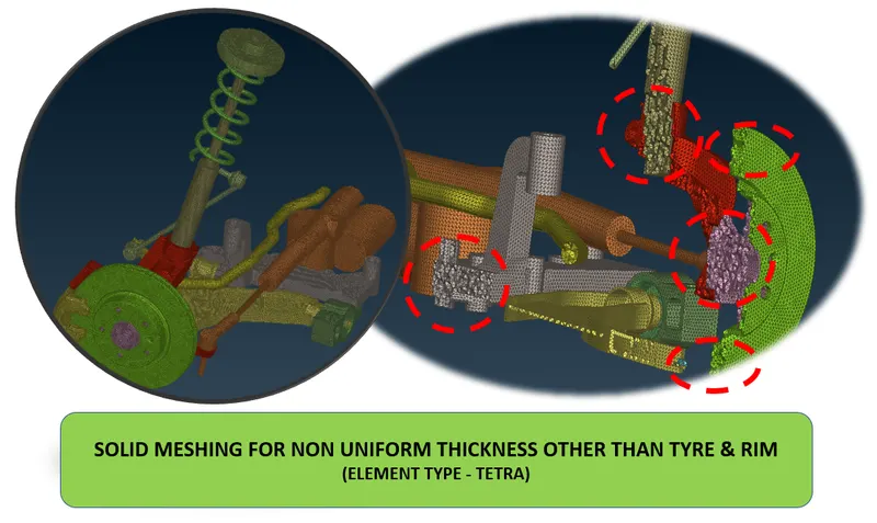
- Figure 13. Volume meshing - Non uniform thickness other than TYRE & RIM
- Volume Mesh - we can see that after spot or mapped mesh there is a hollow space without meshed. Now the mesh should be achieved by getting to volume mesh module.
4. Mid surface is extracted for modelling parts having uniform thickness and performed shell mesh considering quality criteria. Draw shell has been enabled to visualization the thickness of the parts.
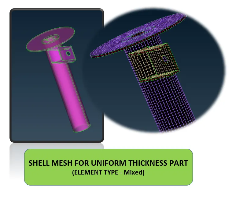
Figure 14. Shell mesh for uniform thickness part
5. 1D element --> CBAR is used to model a suspension coil spring. To visualise the cross section of the spring line element cross section has to be enabled as solid.
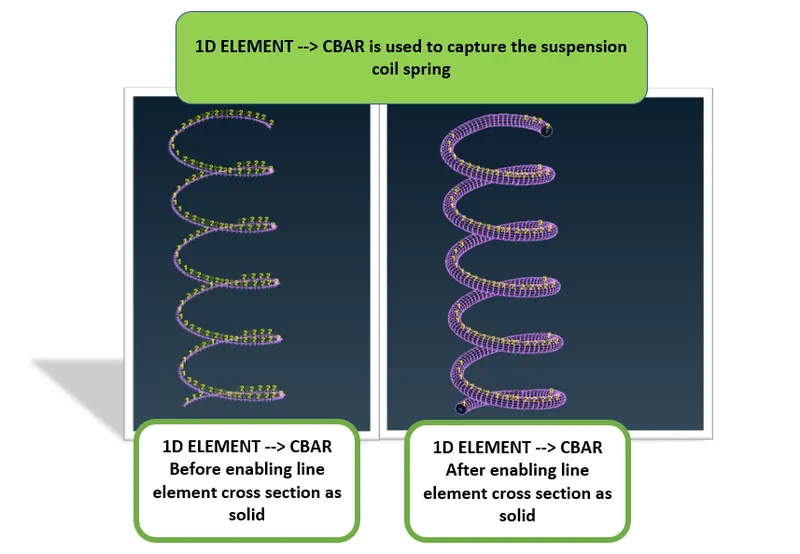
Figure 15. CBAR - 1D ELEMENT
- CONNECTIONS:
- Connections are nothing but representation of bolts, welds, rigid body, etc. in a FE model.
- Here I have deployed various necessary connections such as MANY NODE & TWO NODED RBE2 ELEMENT & Seam weld connctions.
- RBE2 Element -
- In RBE2 element master nodes are independent nodes & slave nodes are dependent nodes.
- Slave node will behave as per the behaviour of the master node.
- RBE2 elements are no property element.
- The different kinds of RBE2 elements are,
- Two nodded RBE2
- To represent the stem of the bolt.
- Many nodded RBE2
- Set
- Two nodded RBE2
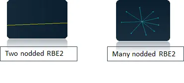
- Figure 16. RBE2 ELEMENT
- RBE2 Element -
-

- Figure 17. RBE2 ELEMENT
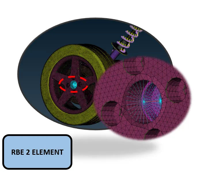
- Figure 18. RBE2 ELEMENT
- Seam weld connection:
Overlap shell element - To weld parallel sheet metal component.
Y – joint shell element – To weld perpendicular sheet metal component.
- Here the seam weld connection is used to join the sheet bracket to the tube.
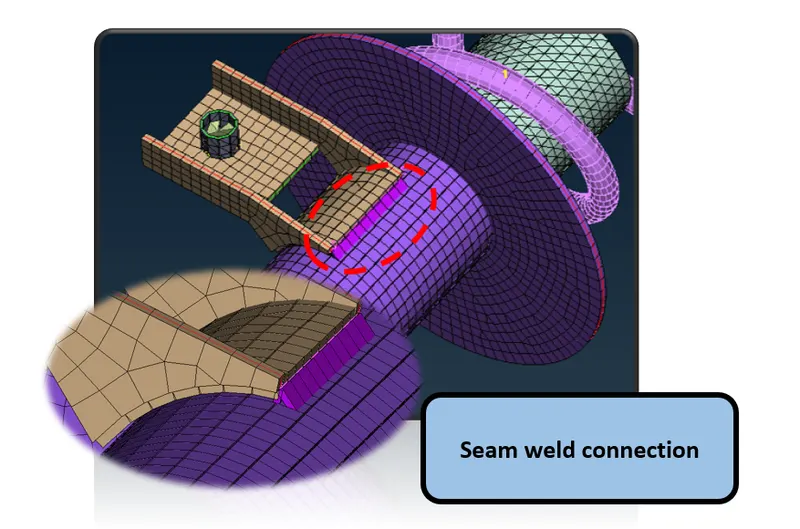
Figure 19. SEAM WELD CONNECTION
TRANSFORM:
To replicate the other half of the suspension system Use transform ---> symmetry to mirror
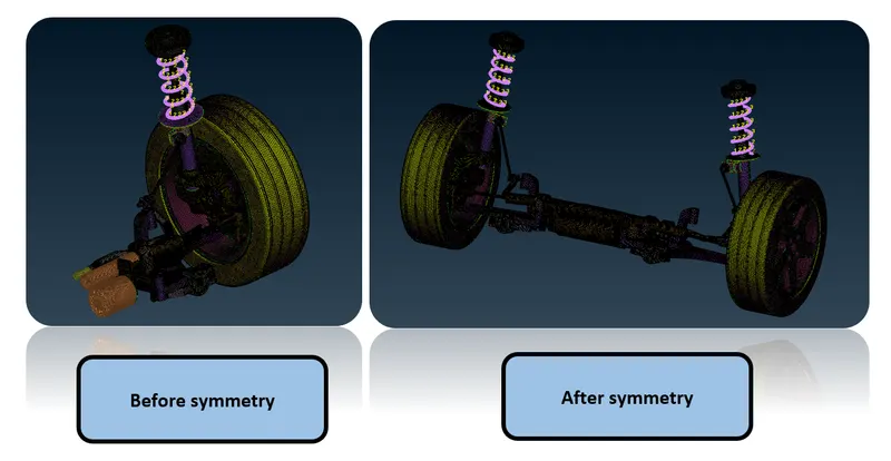
Figure 20.
Hence the whole Rear suspension assembly has been Modeled for NASTRAN deck.
CONCLUSION :
- As per the aim, the given component - Rear suspension assembly of an automobile has been checked for the geometrical errors and mesh with the given element Quality criteria.
- The tetra elements are used to model the component and there has not been any kinks and dips on the surface of the component.
- For the given Rear suspension assembly neccesaary connections has been deployed for NASTRAN deck.
- Overall, the FE Model building has been successfully done.
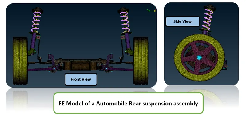
Figure 21. FE Model of an Automobile Rear Suspension assembly
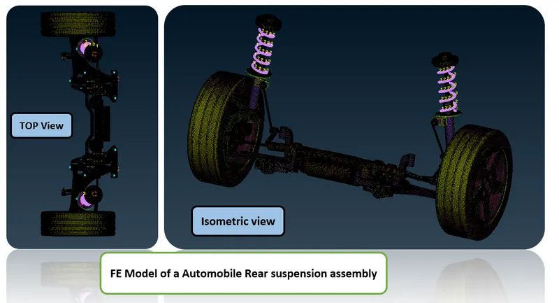
Figure 22. FE Model of an Automobile Rear Suspension assembly
LEARNING OUTCOMES :
At the end of this challenge, I can able to
- Perform FE modelling for any complex automotive system especially for any suspension system.
- Work on ANSA with a flow.