Project-2-Meshing of Door Inner Panel Challenge
Aim:- Shell (2D) Meshing of Car Side Door Inner Panel with given quality criteria and assign thickness.
Objective:-
* To perform 2D shell mesh on the side door panel of car by given criteria.
* To assign thickness for the component.
Procedure:-
1. Import the model:
* First import the given model.
2. Geometry cleanup and topology:
* After importing the model we have to check the geometry and if any is error is found , clear this with cleaning tools such as quick edit tool , surface edit tools, etc.
* In this process we also check for free edges , gaps , overlaped surface and T-edges.
for free edges , gaps , overlaped surface and T-edges.
3. Mid surface extraction:
* For extraction of mid surface first we have to check thickness of surfaces so that we can decide whether go for manual or auto mid surface extraction.
* For thickness measurement we use distance tool. ( geom - distance )
* As we observe that the given component have variable thickness we have to do manual mid surface extraction.
* In given car door model we have to do midsurface extraction separately for components which possesses different-different thickness.
* First we take base surface for midsurface extraction.
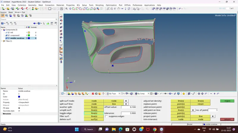
* we observe that the base plate have same thickness, so we go for midsurface extraction through manual process for this we use offset methoth of midsurface extraction.
* Go to surface edit tool and select offset option and select the surface and make duplicate of it and give offset value and check for normals ( we use color normal for our convenience ) and click on offset. ( Geom - surface edit - offset )
* Now we go for other parts such as ribs and other surfaces.
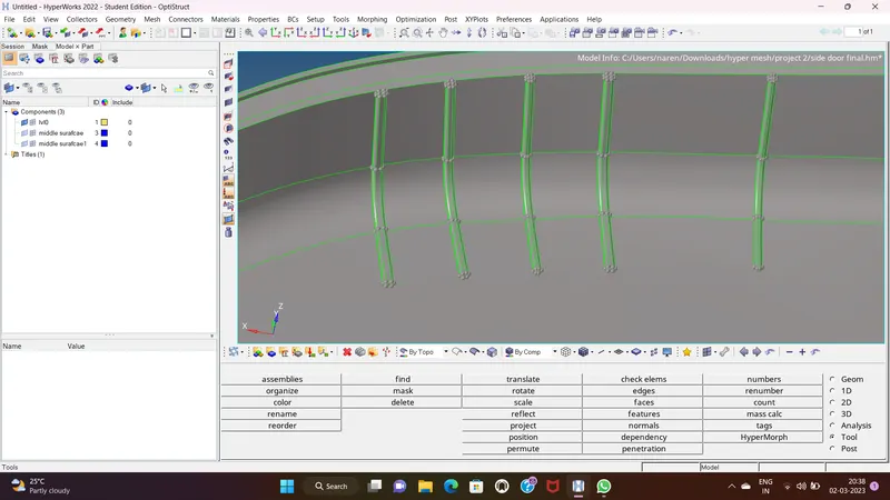
* For these type of surface we can not use offset tool for midsurface extraction. so we use different method.
* First we create mid line for these ribs. for mid line creation we go to geom - line - midline , and select line 1 and line 2 in between midline is created.
* Then we visible only our base plate and use trim with free line tool and do trim on surface and use surface ruled option for creation surface between rib midline and trimmed line which is in base midsurface. so in this manner we get midsurface of ribs which have variable thickness.
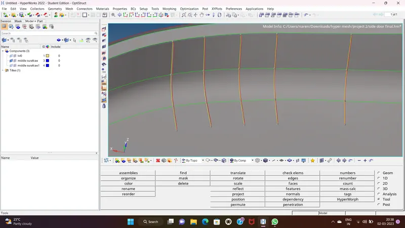
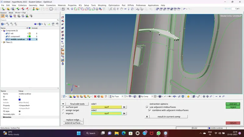
* For midsurface extraction for ribs which have same thickness but these are very filleted surface, so for this we use defeature tool in which we use surf fillet and first we remove fillets and then we use final edit tool for extraction of midsurface for such components.
* In above image we can see that we removed fillets and extract midsurface through final edit tool. ( Geom - midsurface - final edit tool - surface pair - select surf )
* After this we have to connect this rib mid surface to base midsurf for this we use surface extent option , we select line of rib midsurf base and surface in which we connect the rib midsurf.
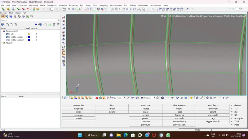
* As above image shows that the rib surface is connected to the base cover mid surface.
* we use final edit tool for midsurface extracton. because they have same thickness.
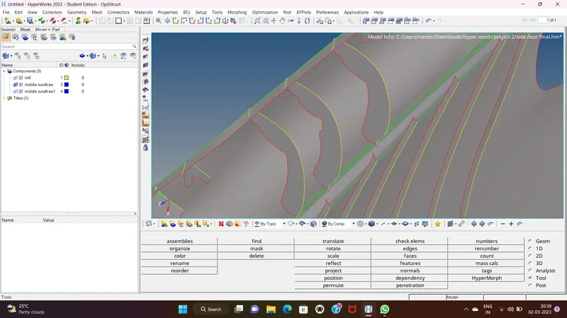
* In above image the thickness of surface is same all over so we use offset option.
* But for joining mid surface to base cover mid surface we use cross extension option of extend tool. ( surface edit - extend - max extension )
* For given instructions for specific components we follow the procedure as we can see in below image.
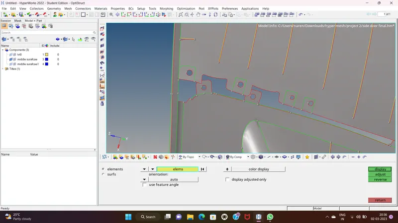
* So in this manner we extract all the mid surface with use of offset tool and final edit tool manually.
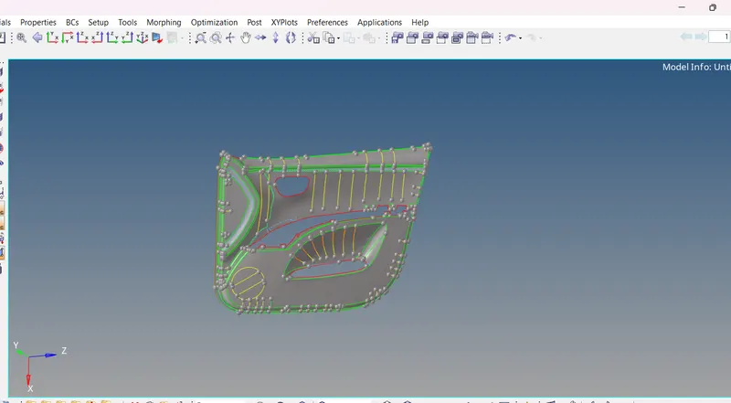
4. Shell Meshing :
* For this given component Batch Meshing is done.
* Before batch meshing we need to set parameter and quality file for meshing.
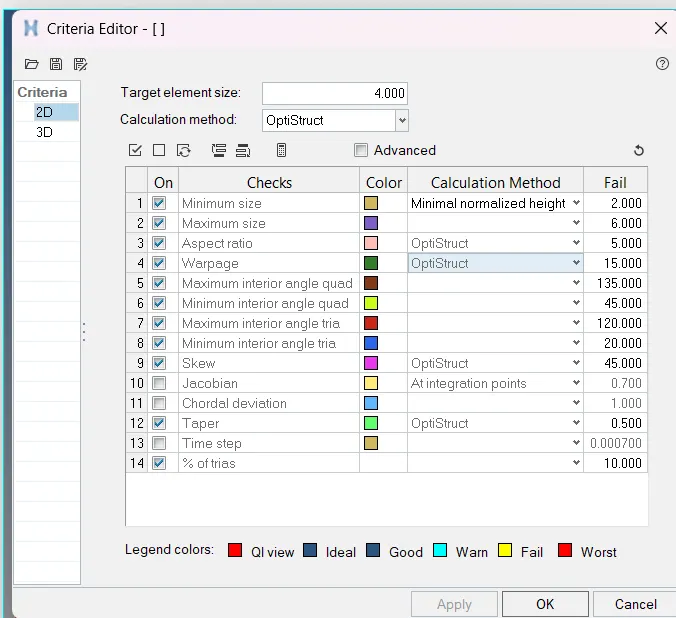
* The criteria file is created as per givne criteria table and parameter file is set by our understanding and complexity of model. These boht file are created and save in pc.
* For batch mesh we go to auto mesh - batch mesh - then we browse the parameter and criteria file from pc , then we click on mesh button. this take some time to mesh.
* After completing the batch mesh process we get mesh for our component but obviously these are lot of failed element and also flow is not appropriate. as we can see in below image.
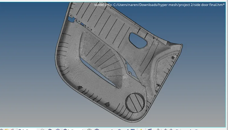
* For fix this issue of failed elements and flow and other importan aspects we use different tools such as rebuild mesh, remesh element , quality index tools, place nodes , replace nodes , translate nodes , etc.
* In this way we pass all element for givne quality criteria.
* After solve this issue of elements failure and fow we check for free edges. ( tool - free edges )
* In above image we can observed that there are no free edges found.
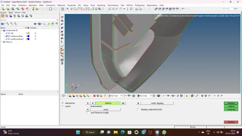
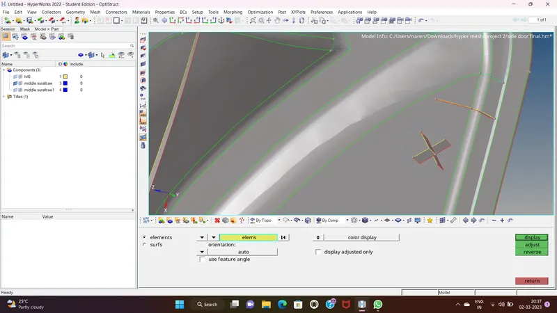
* After this we check for normals so we ensure that all elements have in same normal.
* For checking the normal we go to tools and then normals select elements and click on display.
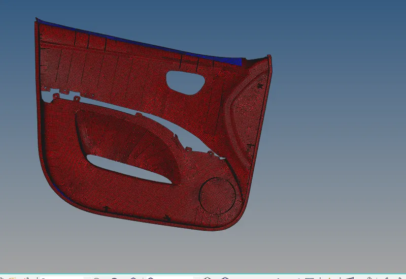
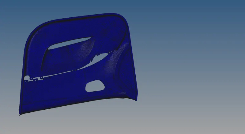
* In this process we found some elements are in different normal so we select these element and click on severse.
5. Creating Properties And Assigning Thickness :
* In this model we have to create property as well as material for this property because we have different - different thickness components.
* So first we measure the thicknesses of components for this we use distance tool.
* According to thickness create the materials.
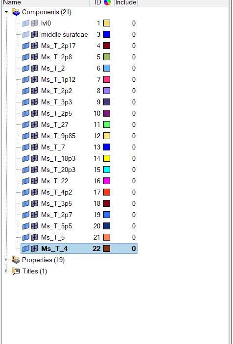
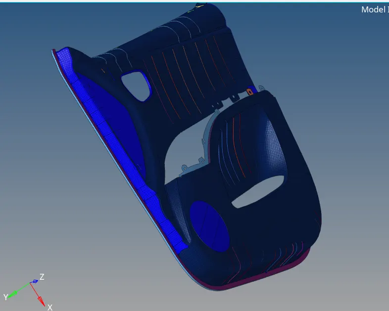
* We isolate components based on thir thickness and create mateials as we can see in above image.
* Then we create the property for these materias and give thickness value to property according to different component's thickness.
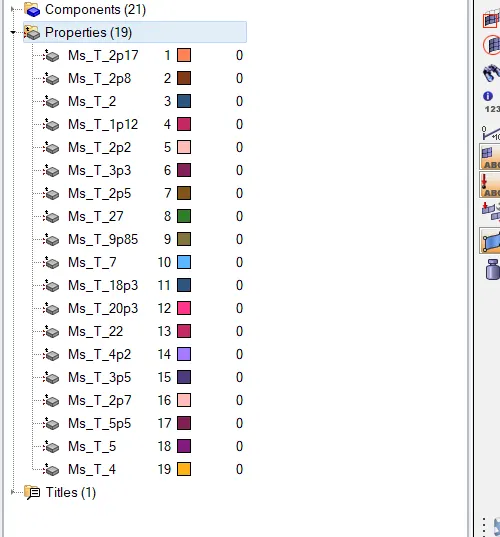
* In this way we create property give thickness and assign to their respective component.
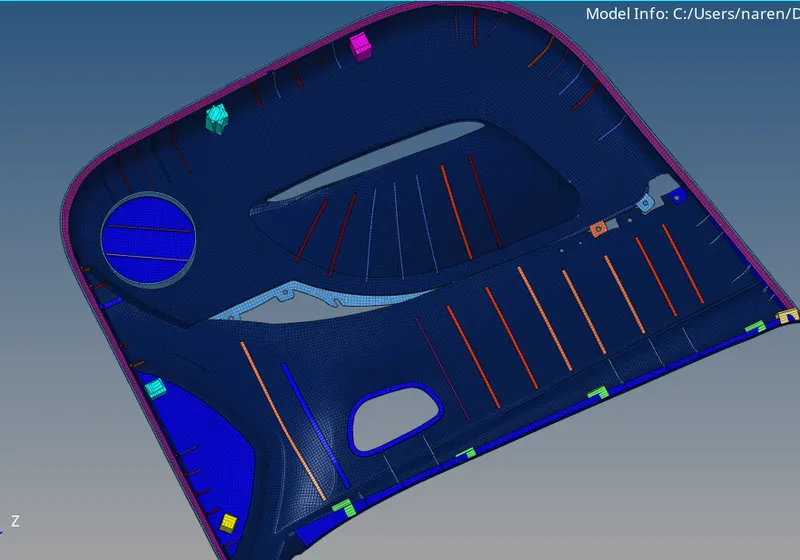
* In below image we can see property are created with assigned thickness to components. we use 2D detailed element view.
Conclusion:-
* In this project we learn 2D meshing of plastic component which have different thicknesses and learn create material ,property and assining thickness