Project-2-Meshing of Door Inner Panel Challenge
AIM :
To perform Preprocessing i.e. extract the Midsurface and Mesh the given Car Side door (Inner Panel) Plastic component by following the specified quality criteria and assigning thickness using HYPERMESH.
SOFTWARE TOOL USED :
Altair HyperWorks Version 2022
OBJECTIVE :
- Import the Car Backdoor Component, and extract the Mid-surface by doing a proper geometry cleanup.
- Generating a good quality Mesh flow on the given geometry with the target element size of 4 units and low tria concentration.
- Checking all the quality criteria parameters and creating different collectors including organizing of the component for assigning thickness.
GIVEN DATA :
- Quality criteria
| S.N | Quality Criteria | Value |
| 1 | Target Element Length | 4 |
| 2 | Aspect Ratio | 5 |
| 3 | Skewness | 45 |
| 4 | Warping | 15 |
| 5 | Taper | 0.5 |
| 6 | Min. Length | 2 Units |
| 7 | Max. Length | 6 Units |
| 8 | Min angle Quad | 45 |
| 9 | Max angle Quad | 135 |
| 10 | Min angle Tria | 20 |
| 11 | Max angle Tria | 120 |
| 12 | Tria % | 10 |
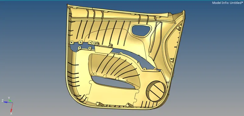
- Cad Model
THEORY :
1. Computer-Aided Engineering (CAE) :
Computer-aided engineering (CAE) is the use of computer software to simulate performance in order to improve product designs or assist in the resolution of engineering problems for a wide range of industries. This includes simulation, validation, and optimization of products, processes, and manufacturing tools.
A typical CAE process comprises of Pre-processing, Solving, and Post-processing steps. In the pre-processing phase, engineers model the geometry (or a system representation) and the physical properties of the design, as well as the environment in the form of applied loads or constraints. Some of the Pre-processors are ANSA and Hypermesh. Next, the model is solved using an appropriate mathematical formulation of the underlying physics. Some of the solvers are ABAQUS (for durability analysis), NVH (for noise, vibration, and harshness analysis), and LS DYNA (for crash, safety, and impact analysis). In the post-processing phase, the results are presented to the engineer for review. Some of the Post-processing are METAPOST and HYPERVIEW.
2. HYPERMESH :
Altair HyperMesh is a high-performance finite element pre-processor that allows users to prepare even the largest models, and produce fine-tuned, high-quality surface meshes of their CAD geometry starting from the import of CAD geometry to exporting an analysis run for various disciplines.
With HyperMesh, you get advanced control over the type and style of meshing done on each CAD face or edge along with many automated tools to make complex meshing tasks a piece of cake. With the high-quality surface meshes from HyperMesh, you can create powerful and efficient 3D meshes for use in Computational Fluid Dynamics (CFD), Finite Element Analysis (FEA), Smoothed particle hydrodynamics (SPH), and more.
3. SIDE DOOR :
Theoretical Framework :
- Door panels serve as an interface between the interior of the car and the inner workings of the door, and between vehicle occupants and the door.
- They are expected to meet a variety of design specifications regarding safety, aesthetics, and functionality. In addition, they are expected to continue the material theme of the dashboard and pillars while concealing intricate electrical and mechanical components for operating locks, windows, and other features.
- The door panel has evolved from a simple two-part system of latch and simple winding mechanism to a more sophisticated enclosure.
- Doors currently have an inner full-width panel consisting of electronic windows, a central locking system, and speakers. These panels typically consist of a foamed core covered with either textiles or plastics.
- Door panels were formerly made of cardboard with an upholstered interior finish of vinyl, leather, cloth, carpet, or other materials for the decorative trim. Modern cars typically have door cards made of plastic, most often using injection molding as well as incorporating other decorative materials.
- The design should incorporate both the necessary service amount and the functional unit (such as "it is strong" and "it looks and feels good") so that a given car door panel would service a car body's life span of 200,000 kilometers (124,274 mi). The door panel typically incorporates other parts that contribute to the appearance, functionality, and ergonomics of the vehicle. These include armrests, switches, or other controls for windows and the locking mechanism, convenience lights, audio speakers, storage compartments, and other features.
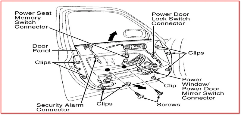
- In most cases, the door card is attached to the car's door frame by visible screws and ones hidden behind decorative plugs or under the armrest, as well as spring clips.
Introduction :
- The Door Trim is a key component of the closure
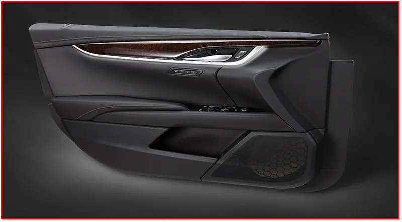
- Door Trim ia an interior component attached to the inner side of the door. This product does more than merely improve the appearance of the vehicle interior. Rather, it is a vital module component that creates a more comfortable interior by providing a variety of accouterments and functions.
- These car door trim panels are made up of plastic materials like Acrylonitrile-butadiene-styrene (ABS), ABS/polycarbonate alloys, polycarbonates, polypropylene, modified polyphenylene ether (PPE), and SMA (styrene-maleic anhydride) resins.
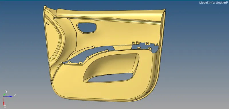
- The model given to us is to be meshed and the mid surface should be extracted manually cause the model given to us is plastic and these plastic components will have varying thicknesses. So the mid surface should be extracted manually.
- This Door trim model will be analyzed in the solver, The crash analysis will be done for this model. So for crash analysis, Try to eliminate the rotational quads as much as possible.
4. Geometry Clean-up :
Designers have different priorities while creating CAD geometry than analysts who are seeking to use the data. Usually, a single smooth surface is divided into smaller patches, each of which is a distinct mathematical face. And often, there will be gaps, overlaps, or other alignment issues at the junction of two surfaces.
In geometry cleanup, analysts integrate several faces onto a single smooth surface to make the geometry more suitable for meshing. This enables the creation of the elements across the entire region at once and eliminates the need for false or unintentional edges in the finished mesh.
Some commands for the geometry cleanup are as follows :
- Geometry -----> Edge edit -----> Replace
- Geometry -----> Surfaces -----> Ruled
- Geometry -----> Quick edit -----> Filler surface
5. Meshing/Mesh generation :
Mesh generation is the process of discretizing the entire model into smaller elements in other words Mesh is a network that is formed of cells and points. Meshing is often used in FEA and CFD domains.
There are two types of meshing, 2D Mesh & 3D Mesh. In 2D Mesh, the mid surface is extracted from the component and then meshing is done on the mid surface whereas in 3D Mesh, direct meshing is done on the component from inside out. The difference between the 2D & 3D mesh is that the mesh type in 2D Mesh is mixed whereas in 3D Mesh the mesh type is Ortho tria (for complex regions such as fillets and hemmings) or Tria (For regions that are flat and not as complicated).
Some thumb rules while meshing :
- The mesh should look rather smooth and regular (An engineer must keep in mind that the analysis is based on the mesh and the mesh quality).
- Use the simplest element type suited for the problem.
- Start with a coarse mesh and understand the modeling results, then use a finer mesh if needed.
- Try to keep mesh-related uncertainties to a minimum if possible. Keep it simple as it can get more complicated on its own.
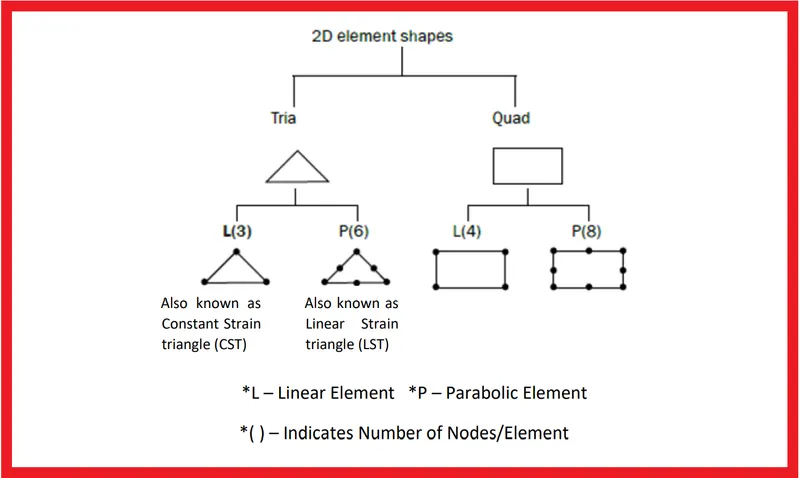
- below is the figure of Different Element Type Options for Shell Meshing
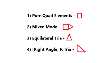
PROCEDURE :
Step 01 : Importing CAD Model.
- The initial step is to import the geometry into HYPERMESH Software.
- There are file formats like IGES, STEP, and Parasolid where we can import these file formats into any CAD, or CAE Software.
- But in hypermesh only three file formats can be imported such as IGES [Initial Graphics Exchange Specification], STEP [Standard for the Exchange of Product Model Data], and Solidworks.
- IGES, STEP, These two are standard file formats that are used most in industries. But nowadays in industries, they are also using the Parasolid file format.
- While importing the file into the graphical user interface, Be sure whether the file is .step or .iges file.
- For importing the model follow the below steps.
Import Model -----> Import Geometry -----> File type - IGES ----> Select Location -----> Click Import -----> Fress F to fit the model.
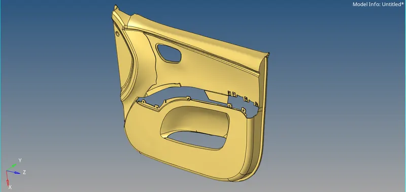
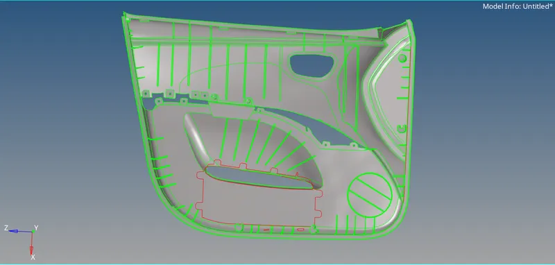
- Switch to the topo mode and examine whether the solid exists in the component or not. If solids exist, Delete the solids as 2d meshing will be done on the component.
- For deleting the solid follow the below steps.
Toolbar -----> Red Cross Symbol (Delete symbol) -----> Solids -----> Select by box selection -----> Delete entity.
Step 02 : Geometry Cleanup
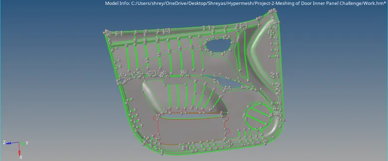
- Before working on the component an Engineer must check for any kind of errors such as extra surface, damaged geometry, free edges in unnecessary areas, missing surface, connectivity errors, unnecessary points on the lines, etc. For this enable wireframe geometry mode and then try to observe and find irregularities and discontinuities in the model. If found then fix it manually.
Step 03 : Separating & Organizing of the Components.
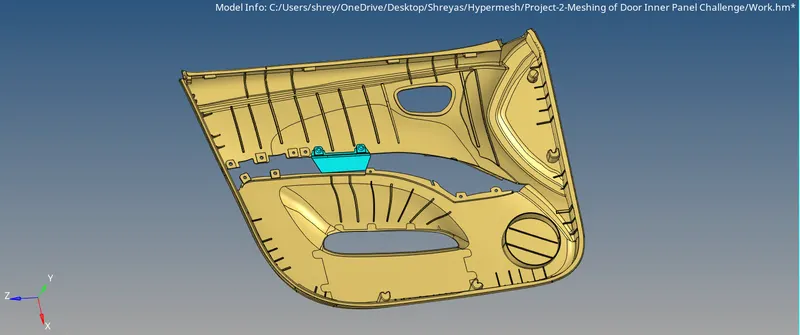
- While examining, it is observed that there are plastic rivets.
- Now these rivets must be detached and organized into different components.
- For separation use the mask command and for assigning them into different components use organize command.
Mask Command :
Tool -----> Mask -----> Select the surfaces which need to be separated -----> Mask -----> Reverse.
Organize Command :
After reverse, Tool -----> Organize -----> Collectors -----> Surfs -----> Select the whole surface -----> Create a component by mouse right clicking on tab area, Create component ------> Select the created component in Deck Component -----> Move.
Step 04 : Extracting midsurface of the base
- The mid surface is generated to reduce the complexity as by simplifying the cad model we get more accurate simulation results in a shorter time.
- In Hypermesh there are many ways to extract the mid surface, an engineer must try to take the exact mid surface on every edge, curve, and complex area. Capturing the exact mid-surface is important because it can later lead to irregular mesh flow and quality issues during meshing.
The following approaches are some methods to extract mid-surface.
- Offset Approach.
- Offset + planes + sweep Approach.
- Offset + planes Approach.
- Skin Offset Approach.
- The above approaches are auto-midsurfacing approaches. there is one more approach i.e. Manual mid-surface through offset command
Manual mid surface (Offset command) :
Geometry -----> Surface edit -----> Offset ----> surfs -----> Insert the offset length (half of the base component) -----> Mouse right-click on the surf and select duplicate -----> Select the surface which needs to be offset -----> offset.
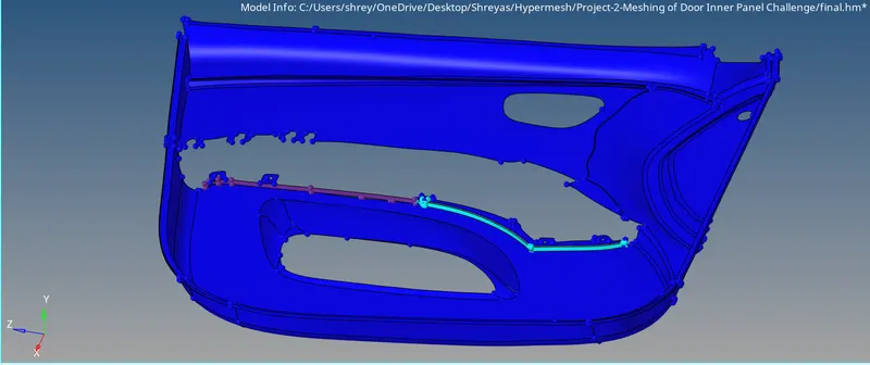
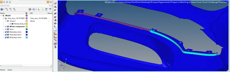
- While midsurfacing the organizing is done side by side in order to keep the component with respect to the thickness.
Step 05 : Defeaturing Fillet Regions.
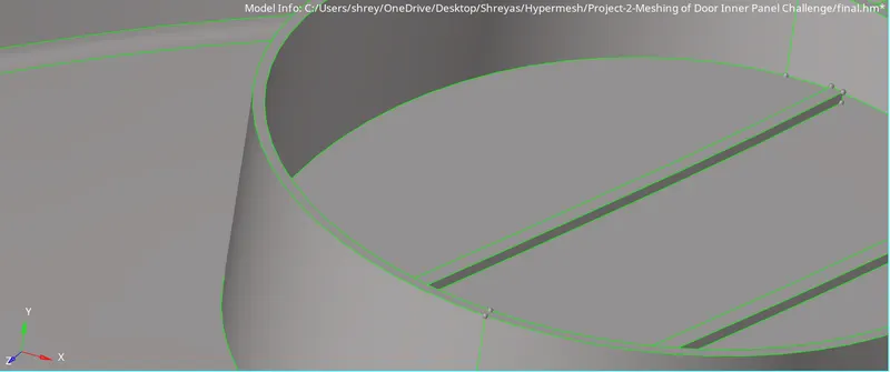
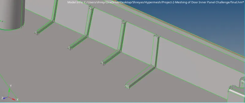
- While meshing and midsurfacing the fillet cannot be captured, Hence defeaturing is necessary.
- All the ribs, cylinder, must be converted into flat surfaces for that all the curves must be eliminated.
- For defeaturing follow the below steps.
Geometry -----> Defeature -----> Surf fillets -----> Surfs -----> Select all the surfaces of the rib and enter the value min radius : 0.5 and Max radius : 10 -----> Find -----> Remove.
Step 06 : Extracting the midsurface of the ribs and translation.
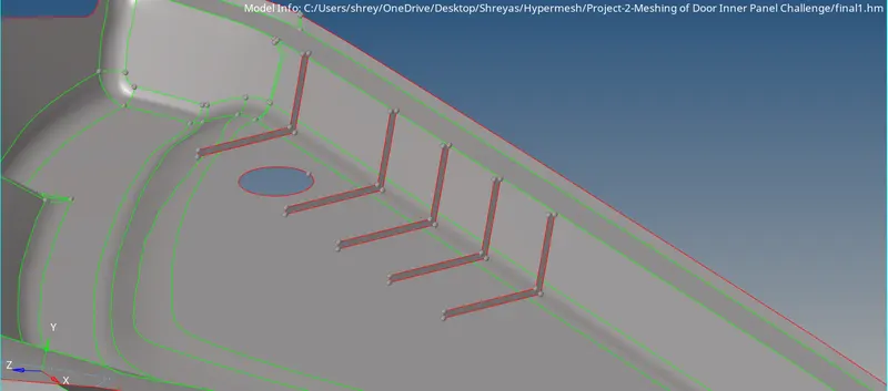
- After defeaturing the ribs it's time to extract midsurface manually with the offset command. (explained in the above step no. 04)
- Once the midsurface is offset, it must be translated according to the parent geometry.
- For translating the midsurface follow the below steps
Tool -----> Translate -----> surfs -----> Select the N1 and N2 -----> Insert the magnitude value as per requirement -----> Translate +.
Step 07 : Geometry Cleanup of all the midsurface and Ribs.
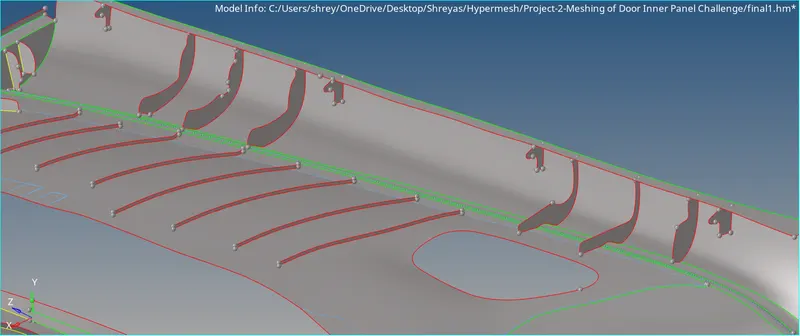
- After extraction of the Midsurfaces of the parent geometry and the ribs, the engineer must clean up the geometry and joins all the ribs with the base mid surface which is hanging on the air.
- For cleanup multiple commands must be used and they are as follows,
Offset command : Geometry -----> Surface edit -----> Offset -----> surfs -----> Insert the offset length (half of the base component) -----> Mouse right-click on the surf and select duplicate -----> Select the surface which needs to be offset -----> offset.
Defeature : Geometry -----> Defeature -----> Surf fillets -----> Surfs -----> Select all the surfaces of the rib and enter the value min radius : 0.1 and Max radius : 10 -----> Find -----> Remove.
Translate : Tool -----> Translate -----> surfs -----> Select the N1 and N2 -----> Insert the magnitude value as per requirement -----> Translate +.
Extend : Geometry -----> Surface edit -----> Extend -----> extend over edges -----> Select the line which must be extended -----> Select the surface for the extend limit -----> extend.
Surface Trim : Geometry -----> Surface edit -----> Trim with nodes -----> node normal to edge -----> Select a node and then select a line for trim.
Hole creation : Geometry -----> Surface edit -----> Trim with lines -----> with lines -----> Select the surface where a hole must be created -----> Select the parent geometry hole edge -----> trim.
Replacing point : Geometry -----> quick edit -----> replace point -----> select a point which must be replaced -----> Then select the other point where the first selected point must be replaced.
Toggle edge : Geometry -----> quick edit -----> Toggle edge -----> Select the line which must be toggled.
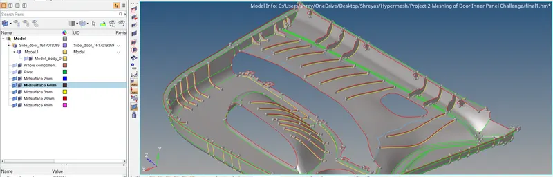
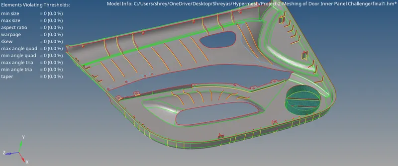
- Here the midsurface is extracted perfectly as required and joined with the base (shown in below fig).
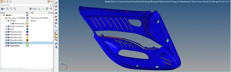
Step 08 : Setting up the Quality Criteria and Mesh Parameter.
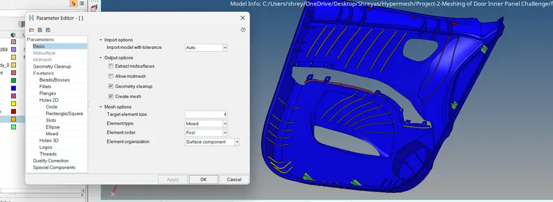
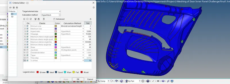
- Setting up the quality criteria as well as the mesh parameters is very important in every pre-processing process. This will make the mesh proper as per the requirements. Here the parameters are given, as per the given data fill the dialogue box, and apply to the component.
For Mesh Parameter :
Title bar -----> Preferences -----> Parameter file setting -----> Basic -----> Fill the necessary data as per the requirement (Target element size : 5, Element type : Mixed) -----> OK.
For Quality Criteria :
Title bar -----> Preferences -----> Criteria file setting -----> Change the criteria values as per given data -----> Fill the necessary data as per the requirement (Target element size : 5, Element type : Mixed) -----> OK.
Step 09 : Mesh Generation
- As the component is very complex and has lots of features such as ribs, dog house, and holes hence the meshing can be done with small portions in order to get a better mesh.
2D -----> Automesh -----> Enter element size as 5mm ----> Mouse Right-click on the Surfs and Select displayed -----> Mesh.
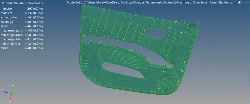
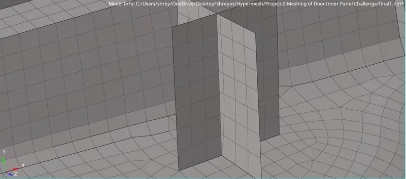
- In some areas there can be seen some connectivity errors, these errors must be solved manually with the following steps
2D -----> Replace -----> click on the node which needs to be replaced ----> click on the node where the node must be replaced.
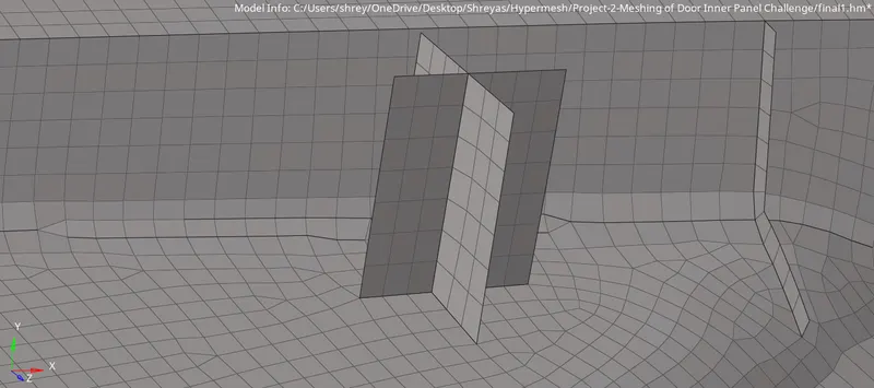
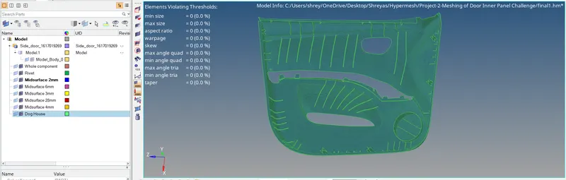
After Meshing there will be some errors that will not follow the quality criteria as well as the parameters and will be seen in different colors. To make the mesh proper some manual adjustments must be done, for that there are a few commands i.e. Create element, Split element, Combine element, smooth, drag tria element, delete element, etc.
- Create element : 2D -----> edit element -----> Create -----> Select nodes where the element must be created -----> Create.
- Split element : 2D -----> edit element -----> Split -----> draw a splitting line by points -----> Split.
- Combine element : 2D -----> edit element -----> Combine -----> draw a splitting line by points -----> Split.
- Smooth : 2D -----> qualityindex -----> Smooth -----> Select the elements which need to be smooth -----> Mouse middle click.
- Drag tria element : 2D -----> qualityindex -----> drag tria element -----> Select the elements which need to be smooth -----> Mouse middle click.
- Delete element : Toolbar -----> Red Cross Symbol (Delete symbol) -----> Select the element that must be deleted -----> Delete entity.
- Rebuild Mesh : 2D -----> Rebuild mesh -----> Select the element which needs to be remeshed -----> Rebuild.
- After using all the above commands the mesh can be created properly and with minimal errors.
Step 10 : Checking the Edges & Normals.
- Checking Edges.
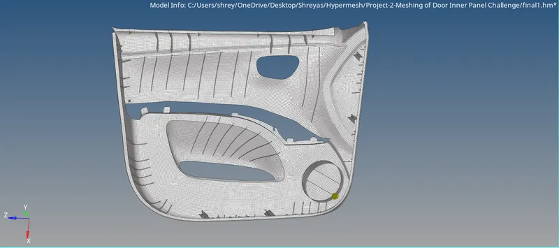
Tools -----> Edges -----> Elements -----> Select the whole component -----> Preview equivalence -----> Tolerance : 0.1 -----> Equivalence.
- Checking Normals.
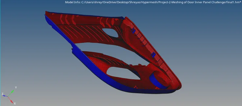
Tools -----> Normal -----> Display -----> Adjust.
LEARNING OUTCOMES :
By doing this challenge, the following aspects can be learned:
- All the necessary tools for pre processing in Hypermesh
- Extracting mid-surface, assigning property and thickness.
- Generating a 2D mesh on the extracted mid-surface.
- Performing basic checks at the end.
CONCLUSION :
- Extracted the mid-surface of the given Car Rear wheel panel model.
- Generated a 2D mesh on the component based on the given quality criteria & parameters, and assigned the thickness.
AIM :
To perform Preprocessing i.e. extract the Midsurface and Mesh the given Car Side door (Inner Panel) Plastic component by following the specified quality criteria and assigning thickness using HYPERMESH.
SOFTWARE TOOL USED :
Altair HyperWorks Version 2022
OBJECTIVE :
- Import the Car Backdoor Component, and extract the Mid-surface by doing a proper geometry cleanup.
- Generating a good quality Mesh flow on the given geometry with the target element size of 4 units and low tria concentration.
- Checking all the quality criteria parameters and creating different collectors including organizing of the component for assigning thickness.
GIVEN DATA :
- Quality criteria
| S.N | Quality Criteria | Value |
| 1 | Target Element Length | 4 |
| 2 | Aspect Ratio | 5 |
| 3 | Skewness | 45 |
| 4 | Warping | 15 |
| 5 | Taper | 0.5 |
| 6 | Min. Length | 2 Units |
| 7 | Max. Length | 6 Units |
| 8 | Min angle Quad | 45 |
| 9 | Max angle Quad | 135 |
| 10 | Min angle Tria | 20 |
| 11 | Max angle Tria | 120 |
| 12 | Tria % | 10 |
- Cad Model
THEORY :
1. Computer-Aided Engineering (CAE) :
Computer-aided engineering (CAE) is the use of computer software to simulate performance in order to improve product designs or assist in the resolution of engineering problems for a wide range of industries. This includes simulation, validation, and optimization of products, processes, and manufacturing tools.
A typical CAE process comprises of Pre-processing, Solving, and Post-processing steps. In the pre-processing phase, engineers model the geometry (or a system representation) and the physical properties of the design, as well as the environment in the form of applied loads or constraints. Some of the Pre-processors are ANSA and Hypermesh. Next, the model is solved using an appropriate mathematical formulation of the underlying physics. Some of the solvers are ABAQUS (for durability analysis), NVH (for noise, vibration, and harshness analysis), and LS DYNA (for crash, safety, and impact analysis). In the post-processing phase, the results are presented to the engineer for review. Some of the Post-processing are METAPOST and HYPERVIEW.
2. HYPERMESH :
Altair HyperMesh is a high-performance finite element pre-processor that allows users to prepare even the largest models, and produce fine-tuned, high-quality surface meshes of their CAD geometry starting from the import of CAD geometry to exporting an analysis run for various disciplines.
With HyperMesh, you get advanced control over the type and style of meshing done on each CAD face or edge along with many automated tools to make complex meshing tasks a piece of cake. With the high-quality surface meshes from HyperMesh, you can create powerful and efficient 3D meshes for use in Computational Fluid Dynamics (CFD), Finite Element Analysis (FEA), Smoothed particle hydrodynamics (SPH), and more.
3. SIDE DOOR :
Theoretical Framework :
- Door panels serve as an interface between the interior of the car and the inner workings of the door, and between vehicle occupants and the door.
- They are expected to meet a variety of design specifications regarding safety, aesthetics, and functionality. In addition, they are expected to continue the material theme of the dashboard and pillars while concealing intricate electrical and mechanical components for operating locks, windows, and other features.
- The door panel has evolved from a simple two-part system of latch and simple winding mechanism to a more sophisticated enclosure.
- Doors currently have an inner full-width panel consisting of electronic windows, a central locking system, and speakers. These panels typically consist of a foamed core covered with either textiles or plastics.
- Door panels were formerly made of cardboard with an upholstered interior finish of vinyl, leather, cloth, carpet, or other materials for the decorative trim. Modern cars typically have door cards made of plastic, most often using injection molding as well as incorporating other decorative materials.
- The design should incorporate both the necessary service amount and the functional unit (such as "it is strong" and "it looks and feels good") so that a given car door panel would service a car body's life span of 200,000 kilometers (124,274 mi). The door panel typically incorporates other parts that contribute to the appearance, functionality, and ergonomics of the vehicle. These include armrests, switches, or other controls for windows and the locking mechanism, convenience lights, audio speakers, storage compartments, and other features.
- In most cases, the door card is attached to the car's door frame by visible screws and ones hidden behind decorative plugs or under the armrest, as well as spring clips.
Introduction :
- The Door Trim is a key component of the closure
- Door Trim ia an interior component attached to the inner side of the door. This product does more than merely improve the appearance of the vehicle interior. Rather, it is a vital module component that creates a more comfortable interior by providing a variety of accouterments and functions.
- These car door trim panels are made up of plastic materials like Acrylonitrile-butadiene-styrene (ABS), ABS/polycarbonate alloys, polycarbonates, polypropylene, modified polyphenylene ether (PPE), and SMA (styrene-maleic anhydride) resins.
- The model given to us is to be meshed and the mid surface should be extracted manually cause the model given to us is plastic and these plastic components will have varying thicknesses. So the mid surface should be extracted manually.
- This Door trim model will be analyzed in the solver, The crash analysis will be done for this model. So for crash analysis, Try to eliminate the rotational quads as much as possible.
4. Geometry Clean-up :
Designers have different priorities while creating CAD geometry than analysts who are seeking to use the data. Usually, a single smooth surface is divided into smaller patches, each of which is a distinct mathematical face. And often, there will be gaps, overlaps, or other alignment issues at the junction of two surfaces.
In geometry cleanup, analysts integrate several faces onto a single smooth surface to make the geometry more suitable for meshing. This enables the creation of the elements across the entire region at once and eliminates the need for false or unintentional edges in the finished mesh.
Some commands for the geometry cleanup are as follows :
- Geometry -----> Edge edit -----> Replace
- Geometry -----> Surfaces -----> Ruled
- Geometry -----> Quick edit -----> Filler surface
5. Meshing/Mesh generation :
Mesh generation is the process of discretizing the entire model into smaller elements in other words Mesh is a network that is formed of cells and points. Meshing is often used in FEA and CFD domains.
There are two types of meshing, 2D Mesh & 3D Mesh. In 2D Mesh, the mid surface is extracted from the component and then meshing is done on the mid surface whereas in 3D Mesh, direct meshing is done on the component from inside out. The difference between the 2D & 3D mesh is that the mesh type in 2D Mesh is mixed whereas in 3D Mesh the mesh type is Ortho tria (for complex regions such as fillets and hemmings) or Tria (For regions that are flat and not as complicated).
Some thumb rules while meshing :
- The mesh should look rather smooth and regular (An engineer must keep in mind that the analysis is based on the mesh and the mesh quality).
- Use the simplest element type suited for the problem.
- Start with a coarse mesh and understand the modeling results, then use a finer mesh if needed.
- Try to keep mesh-related uncertainties to a minimum if possible. Keep it simple as it can get more complicated on its own.
- below is the figure of Different Element Type Options for Shell Meshing
PROCEDURE :
Step 01 : Importing CAD Model.
- The initial step is to import the geometry into HYPERMESH Software.
- There are file formats like IGES, STEP, and Parasolid where we can import these file formats into any CAD, or CAE Software.
- But in hypermesh only three file formats can be imported such as IGES [Initial Graphics Exchange Specification], STEP [Standard for the Exchange of Product Model Data], and Solidworks.
- IGES, STEP, These two are standard file formats that are used most in industries. But nowadays in industries, they are also using the Parasolid file format.
- While importing the file into the graphical user interface, Be sure whether the file is .step or .iges file.
- For importing the model follow the below steps.
Import Model -----> Import Geometry -----> File type - IGES ----> Select Location -----> Click Import -----> Fress F to fit the model.
- Switch to the topo mode and examine whether the solid exists in the component or not. If solids exist, Delete the solids as 2d meshing will be done on the component.
- For deleting the solid follow the below steps.
Toolbar -----> Red Cross Symbol (Delete symbol) -----> Solids -----> Select by box selection -----> Delete entity.
Step 02 : Geometry Cleanup
- Before working on the component an Engineer must check for any kind of errors such as extra surface, damaged geometry, free edges in unnecessary areas, missing surface, connectivity errors, unnecessary points on the lines, etc. For this enable wireframe geometry mode and then try to observe and find irregularities and discontinuities in the model. If found then fix it manually.
Step 03 : Separating & Organizing of the Components.
- While examining, it is observed that there are plastic rivets.
- Now these rivets must be detached and organized into different components.
- For separation use the mask command and for assigning them into different components use organize command.
Mask Command :
Tool -----> Mask -----> Select the surfaces which need to be separated -----> Mask -----> Reverse.
Organize Command :
After reverse, Tool -----> Organize -----> Collectors -----> Surfs -----> Select the whole surface -----> Create a component by mouse right clicking on tab area, Create component ------> Select the created component in Deck Component -----> Move.
Step 04 : Extracting midsurface of the base
- The mid surface is generated to reduce the complexity as by simplifying the cad model we get more accurate simulation results in a shorter time.
- In Hypermesh there are many ways to extract the mid surface, an engineer must try to take the exact mid surface on every edge, curve, and complex area. Capturing the exact mid-surface is important because it can later lead to irregular mesh flow and quality issues during meshing.
The following approaches are some methods to extract mid-surface.
- Offset Approach.
- Offset + planes + sweep Approach.
- Offset + planes Approach.
- Skin Offset Approach.
- The above approaches are auto-midsurfacing approaches. there is one more approach i.e. Manual mid-surface through offset command
Manual mid surface (Offset command) :
Geometry -----> Surface edit -----> Offset ----> surfs -----> Insert the offset length (half of the base component) -----> Mouse right-click on the surf and select duplicate -----> Select the surface which needs to be offset -----> offset.
- While midsurfacing the organizing is done side by side in order to keep the component with respect to the thickness.
Step 05 : Defeaturing Fillet Regions.
- While meshing and midsurfacing the fillet cannot be captured, Hence defeaturing is necessary.
- All the ribs, cylinder, must be converted into flat surfaces for that all the curves must be eliminated.
- For defeaturing follow the below steps.
Geometry -----> Defeature -----> Surf fillets -----> Surfs -----> Select all the surfaces of the rib and enter the value min radius : 0.5 and Max radius : 10 -----> Find -----> Remove.
Step 06 : Extracting the midsurface of the ribs and translation.
- After defeaturing the ribs it's time to extract midsurface manually with the offset command. (explained in the above step no. 04)
- Once the midsurface is offset, it must be translated according to the parent geometry.
- For translating the midsurface follow the below steps
Tool -----> Translate -----> surfs -----> Select the N1 and N2 -----> Insert the magnitude value as per requirement -----> Translate +.
Step 07 : Geometry Cleanup of all the midsurface and Ribs.
- After extraction of the Midsurfaces of the parent geometry and the ribs, the engineer must clean up the geometry and joins all the ribs with the base mid surface which is hanging on the air.
- For cleanup multiple commands must be used and they are as follows,
Offset command : Geometry -----> Surface edit -----> Offset -----> surfs -----> Insert the offset length (half of the base component) -----> Mouse right-click on the surf and select duplicate -----> Select the surface which needs to be offset -----> offset.
Defeature : Geometry -----> Defeature -----> Surf fillets -----> Surfs -----> Select all the surfaces of the rib and enter the value min radius : 0.1 and Max radius : 10 -----> Find -----> Remove.
Translate : Tool -----> Translate -----> surfs -----> Select the N1 and N2 -----> Insert the magnitude value as per requirement -----> Translate +.
Extend : Geometry -----> Surface edit -----> Extend -----> extend over edges -----> Select the line which must be extended -----> Select the surface for the extend limit -----> extend.
Surface Trim : Geometry -----> Surface edit -----> Trim with nodes -----> node normal to edge -----> Select a node and then select a line for trim.
Hole creation : Geometry -----> Surface edit -----> Trim with lines -----> with lines -----> Select the surface where a hole must be created -----> Select the parent geometry hole edge -----> trim.
Replacing point : Geometry -----> quick edit -----> replace point -----> select a point which must be replaced -----> Then select the other point where the first selected point must be replaced.
Toggle edge : Geometry -----> quick edit -----> Toggle edge -----> Select the line which must be toggled.
- Here the midsurface is extracted perfectly as required and joined with the base (shown in below fig).
Step 08 : Setting up the Quality Criteria and Mesh Parameter.
- Setting up the quality criteria as well as the mesh parameters is very important in every pre-processing process. This will make the mesh proper as per the requirements. Here the parameters are given, as per the given data fill the dialogue box, and apply to the component.
For Mesh Parameter :
Title bar -----> Preferences -----> Parameter file setting -----> Basic -----> Fill the necessary data as per the requirement (Target element size : 5, Element type : Mixed) -----> OK.
For Quality Criteria :
Title bar -----> Preferences -----> Criteria file setting -----> Change the criteria values as per given data -----> Fill the necessary data as per the requirement (Target element size : 5, Element type : Mixed) -----> OK.
Step 09 : Mesh Generation
- As the component is very complex and has lots of features such as ribs, dog house, and holes hence the meshing can be done with small portions in order to get a better mesh.
2D -----> Automesh -----> Enter element size as 5mm ----> Mouse Right-click on the Surfs and Select displayed -----> Mesh.
- In some areas there can be seen some connectivity errors, these errors must be solved manually with the following steps
2D -----> Replace -----> click on the node which needs to be replaced ----> click on the node where the node must be replaced.
After Meshing there will be some errors that will not follow the quality criteria as well as the parameters and will be seen in different colors. To make the mesh proper some manual adjustments must be done, for that there are a few commands i.e. Create element, Split element, Combine element, smooth, drag tria element, delete element, etc.
- Create element : 2D -----> edit element -----> Create -----> Select nodes where the element must be created -----> Create.
- Split element : 2D -----> edit element -----> Split -----> draw a splitting line by points -----> Split.
- Combine element : 2D -----> edit element -----> Combine -----> draw a splitting line by points -----> Split.
- Smooth : 2D -----> qualityindex -----> Smooth -----> Select the elements which need to be smooth -----> Mouse middle click.
- Drag tria element : 2D -----> qualityindex -----> drag tria element -----> Select the elements which need to be smooth -----> Mouse middle click.
- Delete element : Toolbar -----> Red Cross Symbol (Delete symbol) -----> Select the element that must be deleted -----> Delete entity.
- Rebuild Mesh : 2D -----> Rebuild mesh -----> Select the element which needs to be remeshed -----> Rebuild.
- After using all the above commands the mesh can be created properly and with minimal errors.
Step 10 : Assigning of Material, Property & Thickness.
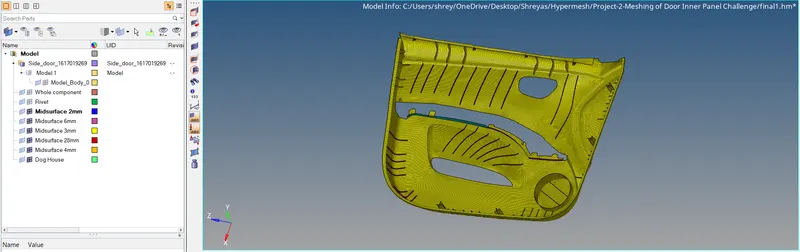
- Here new property and material must be created for assigning them to the Side door component.
For creating and assigning Material :
Mouse right-click on the Tab area -----> Create -----> Material.
For creating and assigning properties :
Mouse right-click on the Tab area -----> Create -----> Property.
- While creating the property give the thickness (T) as per the parent geometry.
Step 11 : Checking the Edges & Normals.
- Checking Edges.
Tools -----> Edges -----> Elements -----> Select the whole component -----> Preview equivalence -----> Tolerance : 0.1 -----> Equivalence.
- Checking Normals.
Tools -----> Normal -----> Display -----> Adjust.
LEARNING OUTCOMES :
By doing this challenge, the following aspects can be learned:
- All the necessary tools for pre-processing in Hypermesh
- Extracting mid-surface, assigning property and thickness.
- Generating a 2D mesh on the extracted mid-surface.
- Performing basic checks at the end.
CONCLUSION :
- Extracted the mid-surface of the given Car Rear wheel panel model.
- Generated a 2D mesh on the component based on the given quality criteria & parameters, and assigned the thickness.