Project 2 - Lane National Highway Roadway Design in Civil 3D
1. Install the Civil 3D software.
For the Creation of surfaces,create the contours.
Open the Civil 3D Sofftware and click on open and then open the Skill lync .dwt tempalte file and save it as a .dwg file
and give a name for the file.
Add the geolocation.
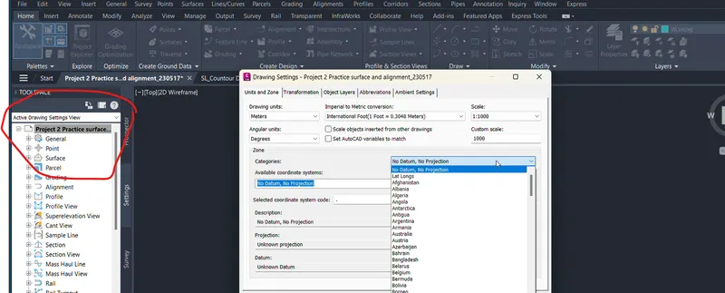
Click On Project name and go to edit drawing settings.
The Dialouge Box Wil Appear select the Type location and provide the details of the location.
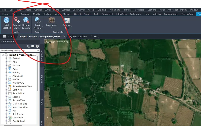
The Geo loaction will be added.
Select the type of map u want to design.
After that copy the contours data from the given data.
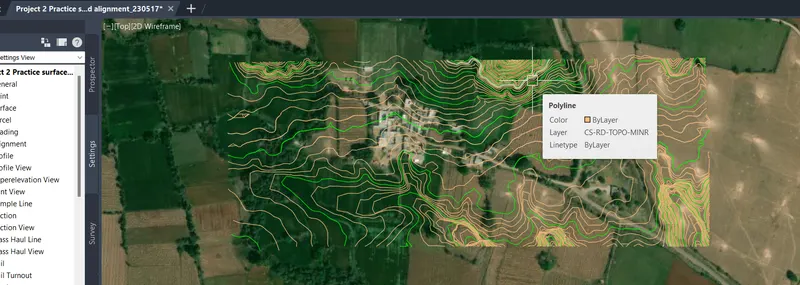
it will be like the above.
After insert of contours.
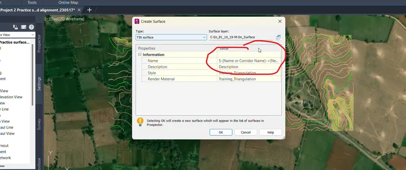
Go to menu bar and click on Surfaces and then click on create surface.
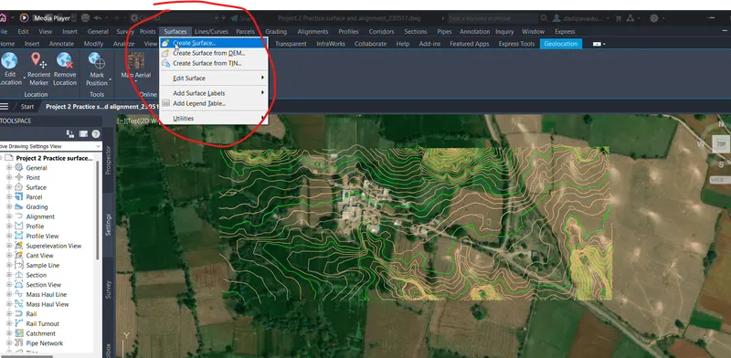
The the Dialouge box will appear. Create the name for the surface and then click on OK.
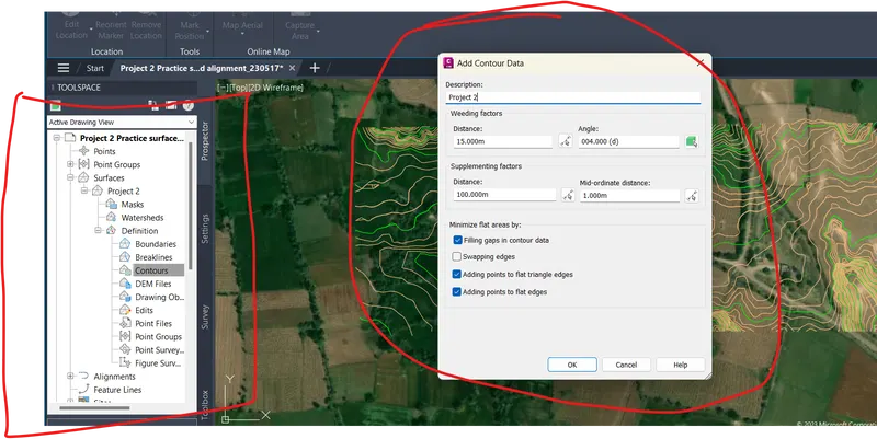
After that go to TOOLSPACE bar and click on settings.
Go to Surface then click on the given name of the surface go to definition in click on it.
In that click on contours then a dialouge box will appear. click on Ok.
Select the countors to which the surface has to be created and then click enter.
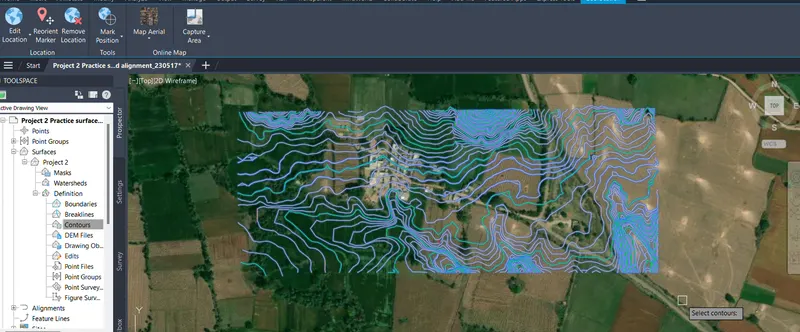
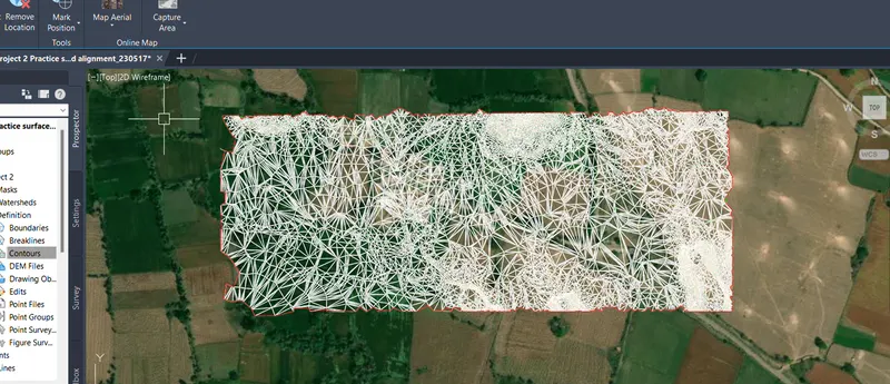
The Surface is created like the above.
Select the created surface and Right click on it and go to surface Properties.
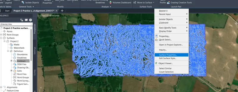
After that a dialouge box will appear like this.
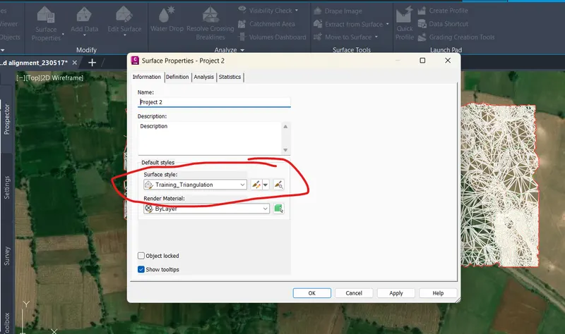
At the marked area change it to border and click on apply.
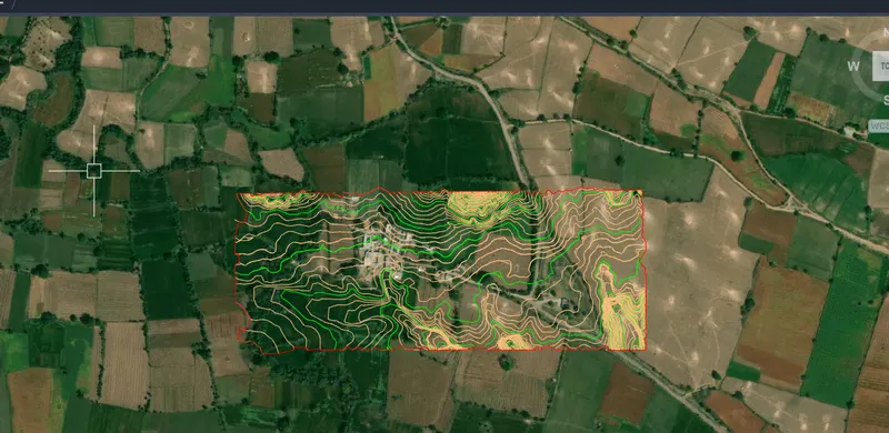
The Creation of Surface is completed.
2.Creation Of Alignment and Profile.
For creating an alignment select the strech/existing road( from the map) where we have to create an alignment.
now From The MENU BAR click on the alignment and right click on create alignment from .
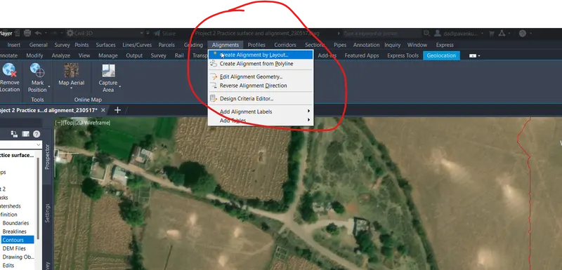
Then a dialouge box wil appear like the below.
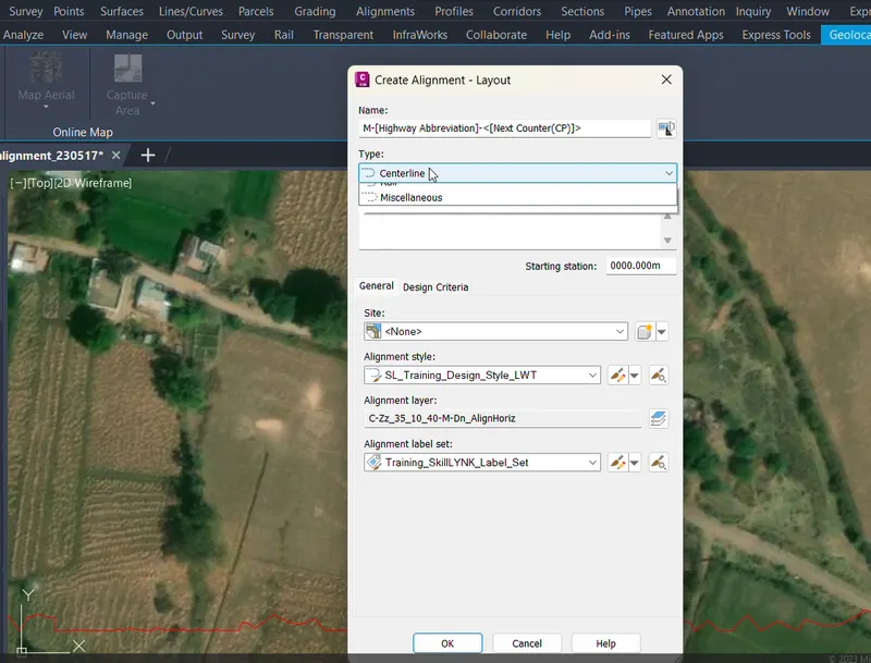
Create a name and select the type of alignment( Centreline) .and click on OK.
And Draw the two entities.
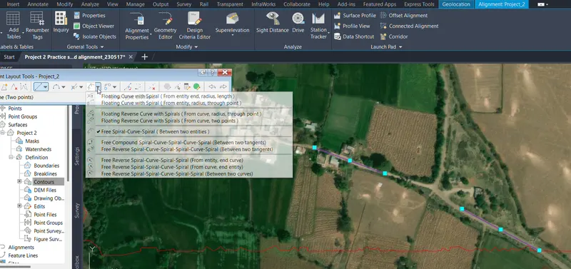
Select free spiral curve and give the radius of curvature as per the given standards.
An then click enter.
the horizontal curve will be created.
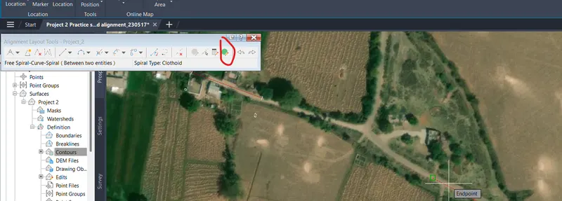
it there is any change in the radius select the alignment click on the geomtry editor and click on the above marked one.
Creation of Profile:
To create Profile
Go to Profile on the menu bar right click and select the Create profile from the Surface.
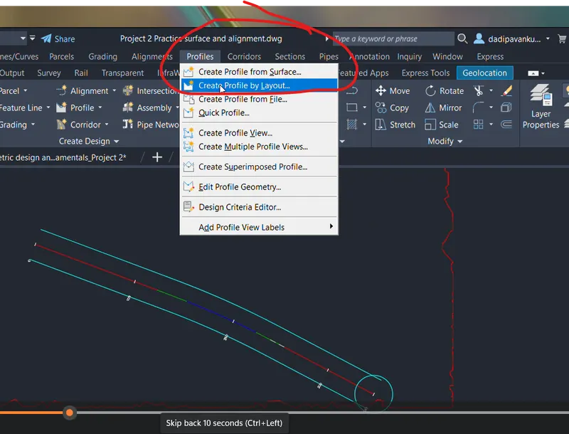
Then a dialouge box appears like this.
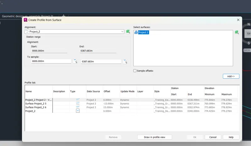
select the alignment name..
give the sample offsets.
Click on add.
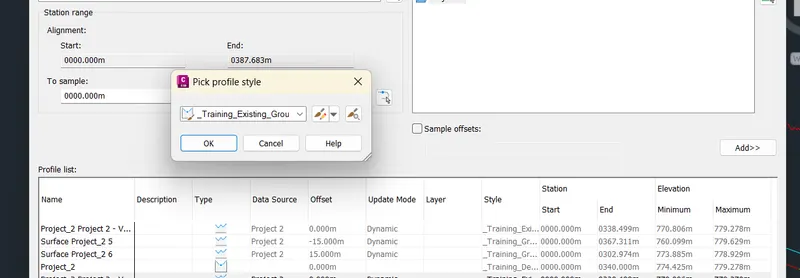
change the styles of the profiles list .
And then click on draw in profile view.
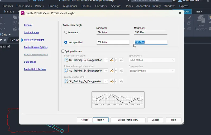
Add the profile view heights and click on next.
Click again on if there is no changes in the profile dispaly options.
then select the appropriate data band sets in the data bands blog....select next
add the Profile hatch options if any needed. and click on create profile view .
pick any where on the dwg file to create the profile.
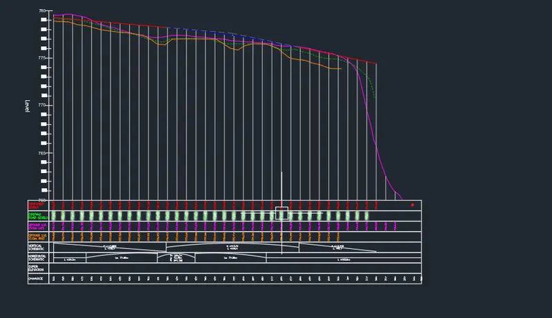
Change the grpah settings based on the datam lines.
From the above procedure we get only the exixting ground levels.To draw the Finished Road Level.
select the profile and right click and create profile.
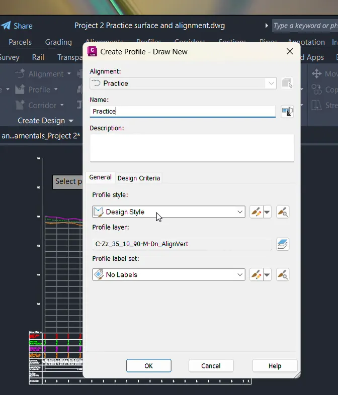
Give the name of the profile and add the profile style and click on OK.
then a dialouge box will appear.
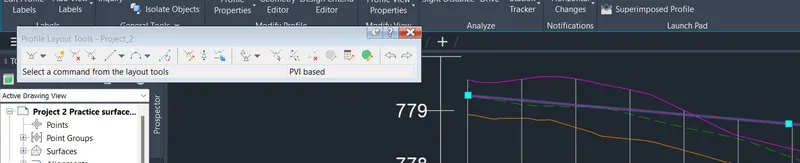
as like horizontal geometry only add the vertical alignment and curves..in the profile view.
Add the Superelevation to the Horizontal geometry.
it is displayed in the profile view.
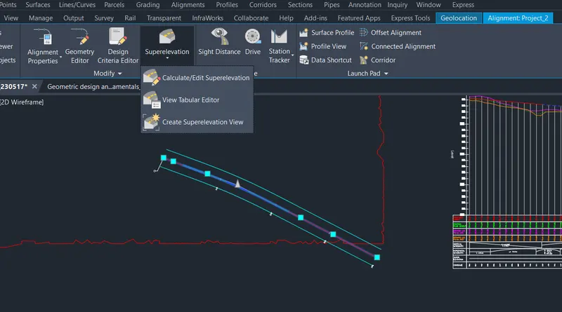
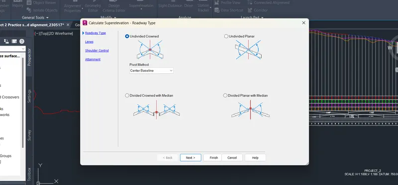
Click on Next After slecting the type of Superelevation required.
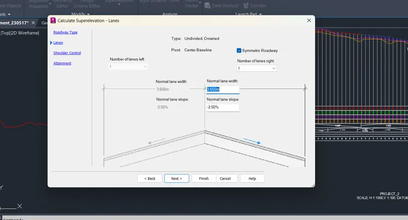
Click on Next after the Design parameters are add to the details.
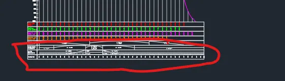
The creation Of Profile is completed.
3.
Creation Of Assembly and Sub Assembly:
Click On the assembly and Click on Create assembly.
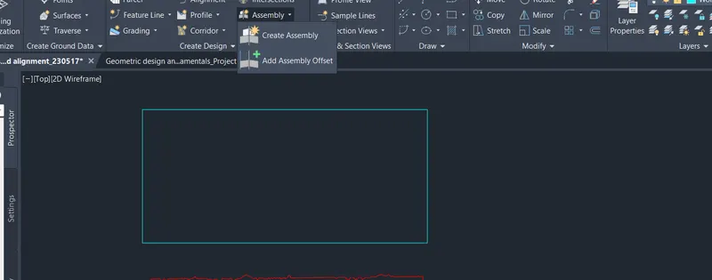
The below dialouge box will appear.Give a name to it and click on Ok.
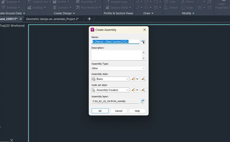
This will appear

Select the Assemble and click on Tool palette the a dialouge will appear.
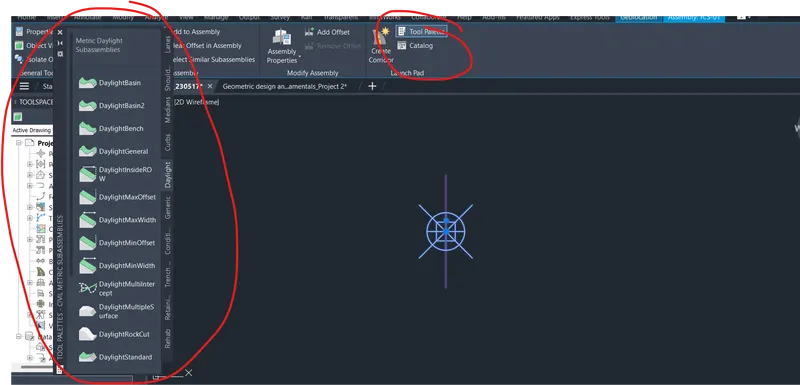
Go lane in the palette and select the type of road.
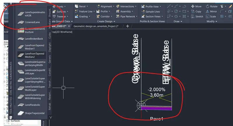
select the sub assemble and click on properties.
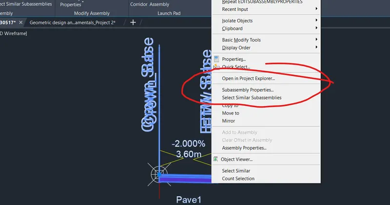
The dialouge box will appear.
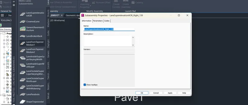
Go to Parameters you can change the width and superelevations of the lane.
the lane width should include the paved shoulder width in it.
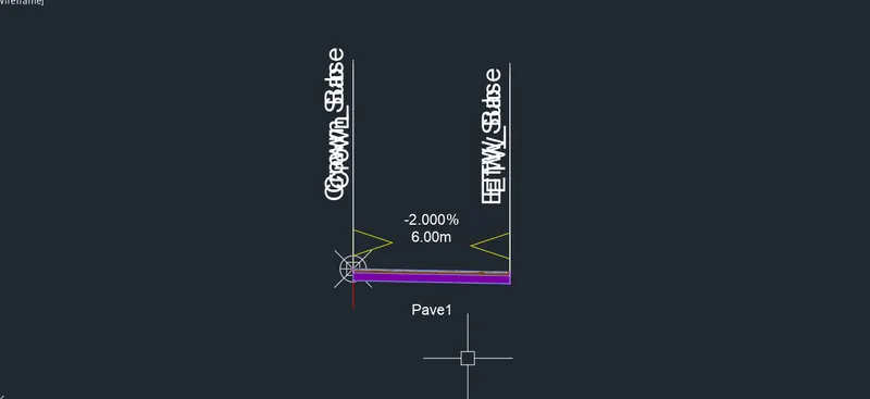
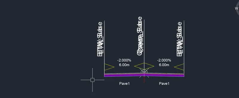
Miror the sub assemble we can get the Formation width of the road.
Similarly, By adding the shoulder and daylight we can get the Typical cross section .
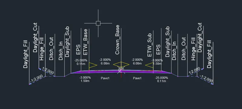
Creation of assembly and sub assemblies has been completed.
4.
Corridor development
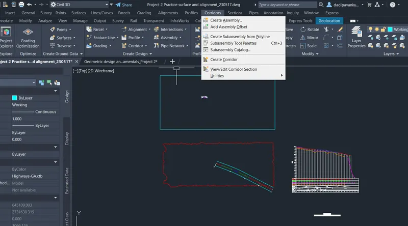
click on corridor in the menu tab and click on create corridor.
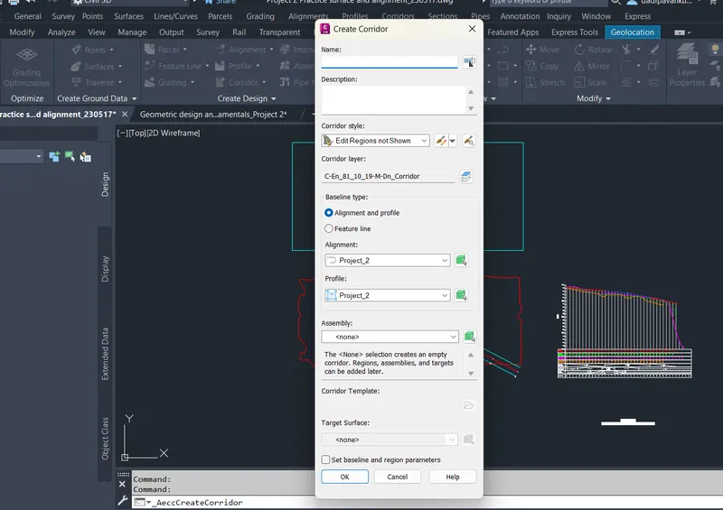
then this window will appear.
In this give the name of the corridor. name of the saved alignment,Assemble,Surface area. And Click On Ok.
Then The Dialouge box will appear.
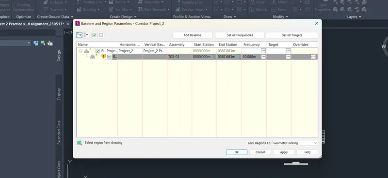
Click on the marked area.
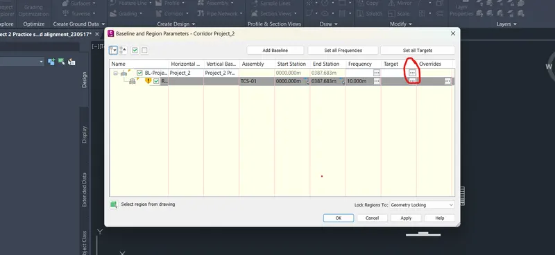
Then This dialouge box will appear.
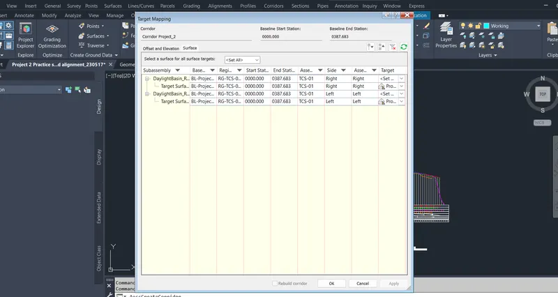
select the surface and click on ok. It will be back to previous dialouge box.then click on apply and click on Ok.
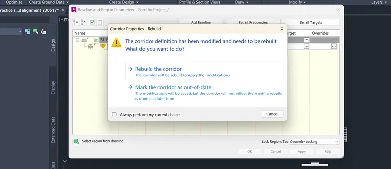
Click on rebuild the corridor. and click ok
Corridor has been completed.
Go to toolspace click on corridor and click ok rebulid corridor.
5.
Section line and detail cross section.
Click On sections in the menu bar and click on create sample line.
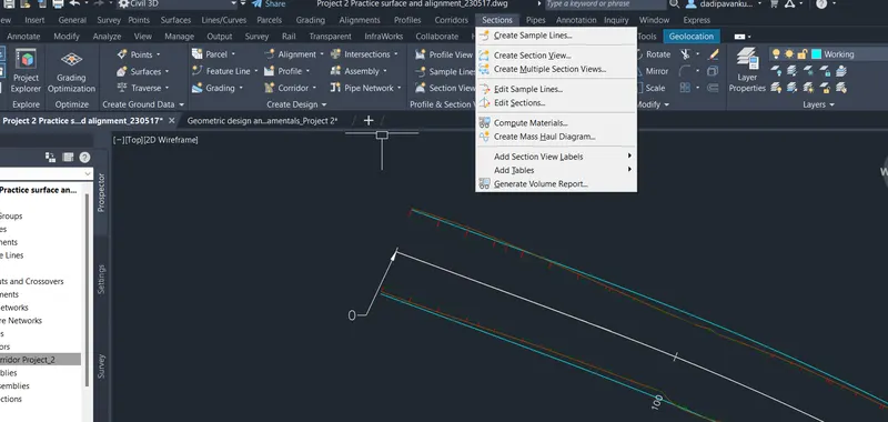
Select the alignment line and press enter then the dialouge box will appear.
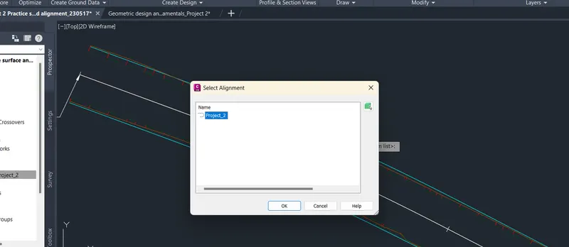
Click on Ok. Then the dialouge box will appear.
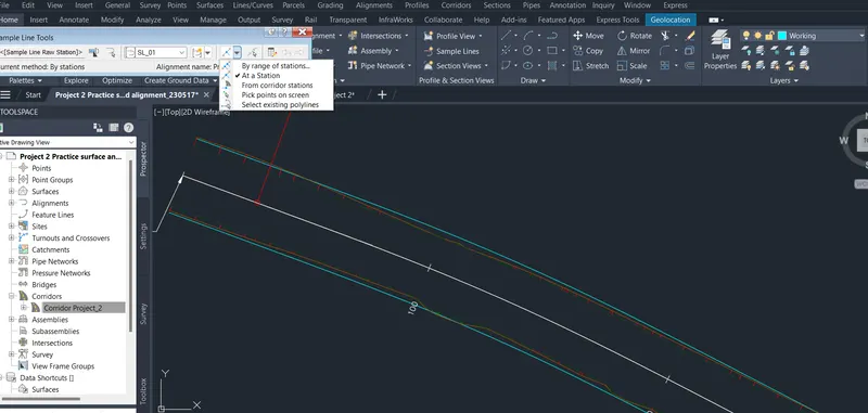
Select the by range of station. click on the corridor.
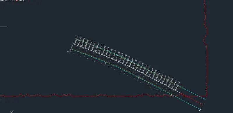
Then the chainage will appear.
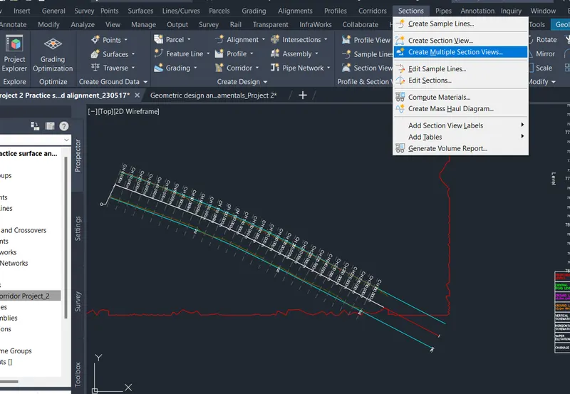
now again click on the sections.click on the multiple section views.then the below dialouge box will appear.
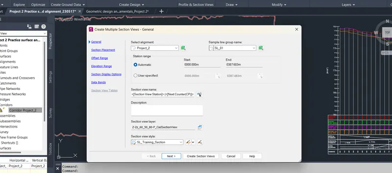
select the surface and fill all the required details.and click on next.
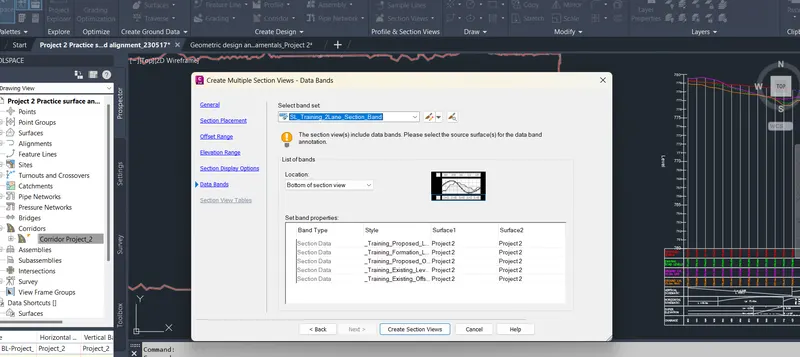
Select the Type of band and click on create on vertical sections.click on the screen.
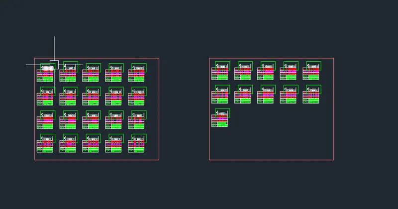
The sections views has been created.
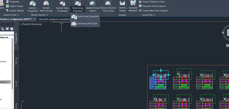
select on section in the and click on the view group properties.the dialouge box will appear.
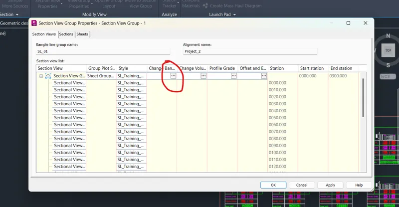
click in the marked area then the dialouge box will appear.
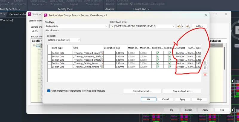
Change the surface 1 to Corridor top
surface 2 to corridor bottom and click apply and click on ok.
the ok again.
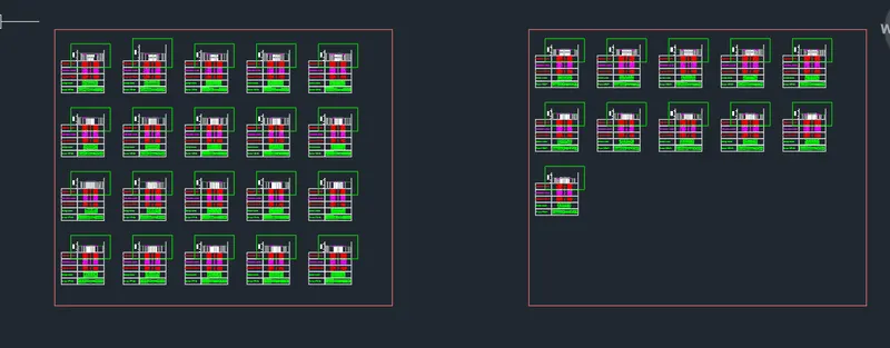
The creation of Sections has been completed.