Project 2 - Lane National Highway Roadway Design in Civil 3D
Develope the road geometric design for 2lane NH concrete road with paved shoulder for 80kmph design speed from the provided data.
1.Creation of surface
Method-1 By using surface XML data
Go to insert>click on land xml>go to surface xml saved location> select surface xml>click on open>click ok
Method-2 By using contour data
Click on file>click on open>go to saved contour data saved location>select SL contour data>click on open>contour data appears on screen
To create surface
Select contour data on single left click> type ctrl c in command bar> drawing 1>go to edit> select paste to original co-ordinates
In toolspace bar, select surface(right click)>create surface>edit the surface name(surface eg)> click on ok
Surface>surface eg>definition>select contours(right click)>add>click on ok
Select all contours>enter
Type LAYOFF in command bar and click on major & minor contours>Esc
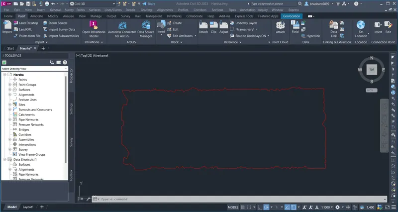
Surface is created.
2.Alignment & profile design.
Go to alignment>create alignment by layout
In create alignment tool box
Give the name,type in general click on ok
Alignment layout tool box will come
To create alignment first set geographical co-ordinate system
Go to settings>click on saved project name(right click)>edit drawing settings(select co-ordinate system code)>apply>ok
Go to geolocation>map>select map aerial
Method-1
In alignment layout tools, select tangent-tangent(no curves)>draw alignment>select free curve fillet(b/w two entities,radius)
curve is inserted b/w two tangents
Method-2
Go to alignment>create alignment layout
Give the name,type then click on ok
In alignment layout tool,select fixed line(two points)>draw two tangents
select free spiral-curve-spiral(b/w two entities)>draw spiral-curve-spiral b/w two tangents
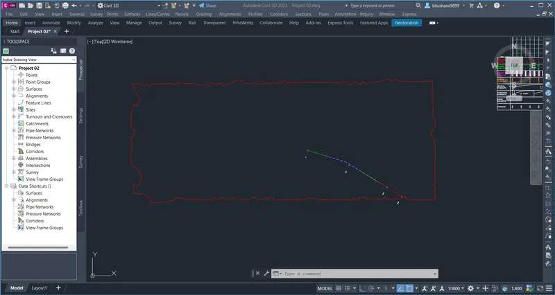
Alignment is created.
Creating profile view
Go to profile>create profile from surface>click on saved surface name>click on add>draw in profile view
Give the profile view name,profile view style,station range,profile view height,data bands
then click on create profile view.
Creating profile
Go to profile>create profile by layout
create profile-draw new toolbox will appear
give name,profile label set,profile style as per requirement >click on ok
In profile layout toolbar
Select fixed tangent(two points)
Insert PVI
Select PVI click on profile>Esc, select free vertical curve(parabola)
select first entity & second entity as well as specify curve length.
3.Creation of assembly & subassembly
Creation of assembly
Assembly is nothimg but typical cross section
Go to corridor>select create assembly
give the assembly name then put on screen with rectangle for our reference
Creation of subassembly
Select assembly>click on tool palette>lanes>lanes from redmedian1>click on assembly(on circular point)
Click on assembly>subassembly properties>select parameters
Lane width=3.5m
cross slope=-2.5%
pave 1 depth=0.280m
pave 2 depth=0.150m
base depth=0.2m
sub base depth=0.5m, click on apply>ok
Next, is create earthen shoulder or embankment slope
Click on subassembly>tool palette>shoulder
to edit earthen shoulder,click on subassembly>subassembly properties
lane width-1m
shoulder slope=-3%
day light slope=2:1
sub base slope=-3%
subassembly is created as per our requirement
4.corridor development & Section line or sample line
Click on corridor>create corridor
give corridor name, alignment,profile,assembly and target surface, then click on apply>ok>rebuild corridor
In toolsapce>prospectus>go to corridor(right click)>properties
In information>select object style as edits
surfaces>add surfaces top
add bottom surface and datum
add breaklines>check both
overhang>toplinks & bottomlinks, then click on apply>ok
Creation of sample lines or section lines
Click on section>create sample lines
select alignment>ok
give the sample line name
then select by range of stations
left swath width=25m
right swath width=25m
Set sampling increments as per client requirement(for chainage intervals)
set at range starts:true
at range end:true
at horizontal geometry points:false
at superelevation critical stations:false then click on ok
right click on screen.
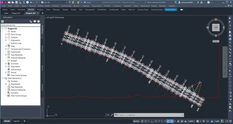
sample lines will be created
5.Creation of detailed cross section views & generating quantity report
To create cross section
Click on section>create multiple section views
In general
select alignment
select sample line group name
section view name
secvtion view style
In section placement-select draft
offset range-automatic
elevation range-automatic
section display option-
in cut-hatcting ansi 31 size2
in fill-hatching ansi 38
Data bands-design & existing levels with offsets
set band properties
| surface1 | surface2 |
| 1.corridor top | corridor top |
| 4.corridor top | corridor top |
section view table
type:-material,click add>ok
click on create section view. cross section is created.
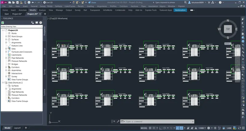
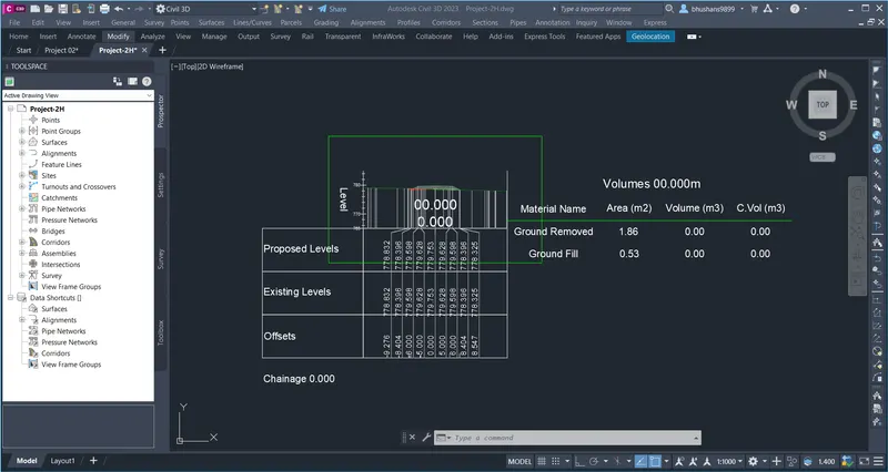
Cross section views
Cross section @ 0 chainage
Cross section @ 260 chainage
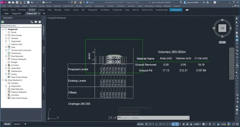
Quantiy report
To calculate quantity
Click on section>compute materials
select alignment name
select sample line group name>ok
compute material toolbox will appear
quantity takeoff criteria=standard
EG=surface1
datum=bottom surface
Again,
click on section>compute materials
edit material list>apply>ok
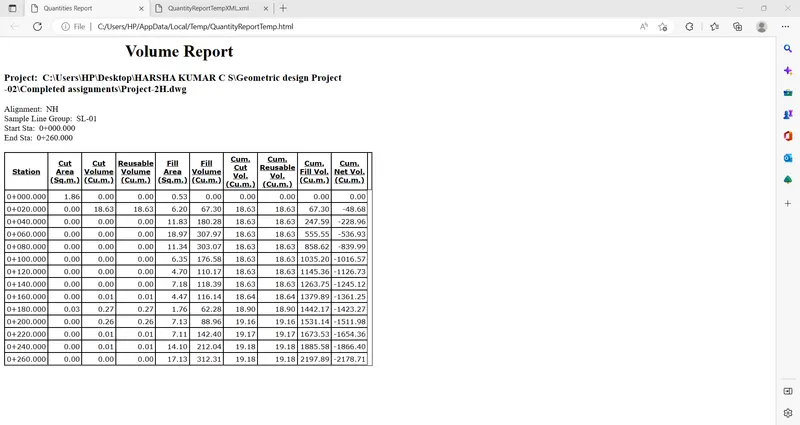
click on section>generate volume report
in report quantities
select alignment
select sample line group
select material list
select a style sheet:-earthwortk>ok