Project 2-Highway Assistant-Lane Changing Assistant
Highway Assistant – Lane Changing Assistant
Introduction to the Feature:
The Highway Assistant supports the driver and takes over the longitudinal and lateral guidance of the vehicle in monotonous driving situations on highways. The partially automated function can automatically start, accelerate, brake as well as steer the vehicle to a certain extent. The driver has to permanently supervise the system and be ready to take over the complete control of the vehicle at any time.
Drivers are taught to assess surrounding traffic before changing lanes by checking their rearview and side mirrors and looking over each shoulder. However, even for those who follow this sequence of checks, the vehicle's blind spot – the area alongside and just behind the vehicle – is a constant source of danger and often the cause of serious accidents. Even vehicles approaching quickly from behind can pose a risk. To make changing lanes safer, this feature has been developed.
Basic Working Principle:
Highway Assistant is a partially automated driving function for a speed range of up to 180 km/h (112 mph) on highways. It combines the radar-based longitudinal guidance of Adaptive Cruise Control (ACC) with the video-based lateral guidance of lane keeping support in one system. Highway Assistant can be supplemented by an automatic lane change initiated and monitored by the driver in a speed range of 60 – 130 km/h (35 – 80 mph).
The lane Change Assistant works by using two mid-range radar sensors that are concealed in the rear bumper – one on the left, one on the right. These two sensors monitor the area alongside and behind the car. Powerful control software collates the sensor information to create a complete picture of all traffic in the area behind the vehicle.Whenever another vehicle approaches at speed from behind or is already present in the blind spot, a signal such as a warning light in the side mirror alerts the driver to the hazard. Should the driver still activate the turn signal with the intention of changing lanes, the system issues an additional acoustic and/or haptic warning.
Problem Statement:
To develop one specific requirement of Highway Assistant – Lane Changing Assistant algorithm. Please note that the whole Highway Assistant – Lane Changing Assistant is a very huge algorithm & only one small part of the logic is implemented here. Idea is to familiarize with concepts of Autosar Software Component Development in MATLAB Environment by following the Model Based Development guidelines. The Project must be done keeping in mind the following processes & steps.
- This model must be developed in MATLAB Simulink per MBD guidelines.
- Code Generation Profile must be Autosar Coder.
- Simulink Data Dictionary must be created for the model & must be linked to the model.
- All the input & output signals must be mapped into the Autosar Editor.
- Model Advisor Report is mandatory & this will be followed by Code Generation.
Input Signals:
|
Name of the Signal |
Data Type |
Range |
|
Highway_Input_Signal |
uint8 |
0 - 255 |
|
Enable_Display |
uint8 |
0 – 255 |
|
Input_Switch |
uint8 |
0 – 255 |
|
Lane_Input_Signal |
uint8 |
0 - 255 |
Local Signals:
|
Name of the Signal |
Data Type |
Range |
|
Highway_Display_Mode_1 |
uint8 |
0 - 255 |
|
Highway_Display_Mode_2 |
uint8 |
0 – 255 |
|
Highway_Display_Mode_3 |
uint8 |
0 – 255 |
|
Highway_Display_Mode_4 |
uint8 |
0 – 255 |
|
Lane_Display_Mode_1 |
uint8 |
0 – 255 |
|
Lane_Display_Mode_2 |
uint8 |
0 – 255 |
|
Lane_Display_Mode_3 |
uint8 |
0 – 255 |
|
Lane_Display_Mode_4 |
uint8 |
0 – 255 |
Output Signals:
|
Name of the Signal |
Data Type |
Range |
|
Display_Mode_1 |
uint8 |
0 - 255 |
|
Display_Mode_2 |
uint8 |
0 – 255 |
|
Display_Mode_3 |
uint8 |
0 – 255 |
|
Display_Mode_4 |
uint8 |
0 - 255 |
Creation Of Sldd:
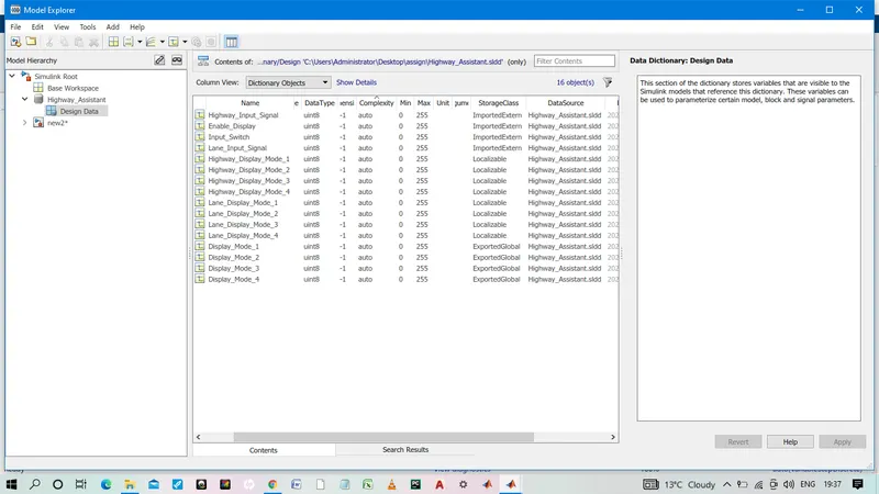
Requirement No 1 [Highway_DisplayUnit]:
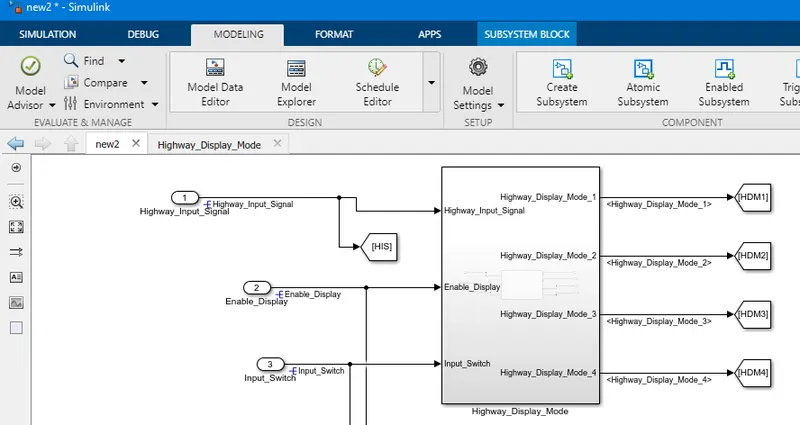
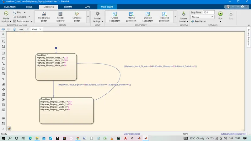
Inputs to this particular subsystem are “Highway_Input_Signal”, “Enable_Display”, “Input_Switch”. These three input signals, when assigned to a particular value will give output signals of specific value. The output signals are “Highway_Display_Mode_1”, “Highway_Display_Mode_2”, “Highway_Display_Mode_3”, “Highway_Display_Mode_4”. The requirement must be implemented in the form of a Stateflow logic.
|
Condition |
Action |
|
Highway_Input_Signal = 1 Enable_Display = off Input_Switch = on |
Highway_Display_Mode_1 = 232 Highway_Display_Mode_2 = 183 Highway_Display_Mode_3 = 41 Highway_Display_Mode_4 = 94 |
|
Highway_Input_Signal = 1 Enable_Display = on Input_Switch = on |
Highway_Display_Mode_1 = 213 Highway_Display_Mode_2 = 183 Highway_Display_Mode_3 = 9 Highway_Display_Mode_4 = 94 |
Step 1:
Created a subsytem with given input .Inside the subsytem , a chart is created with given input and outpput.Inside the chart, both condition is used by using state.
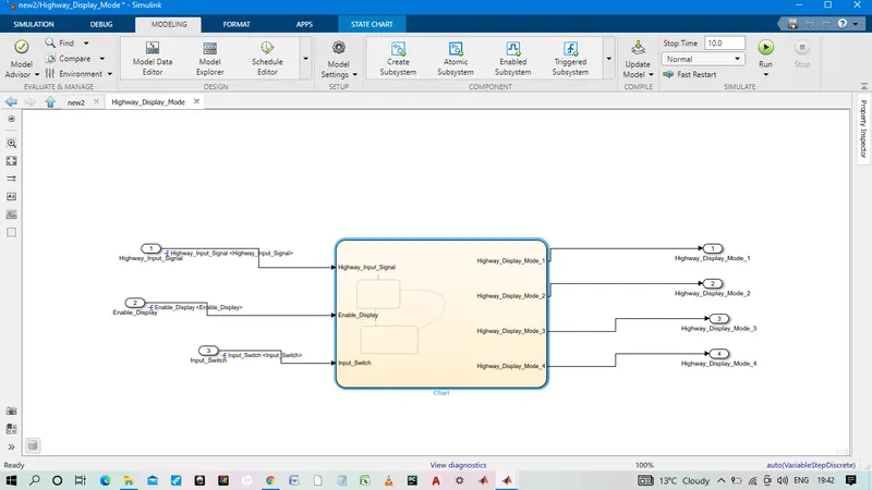
Input and outport port of chart is resolved as shown below.
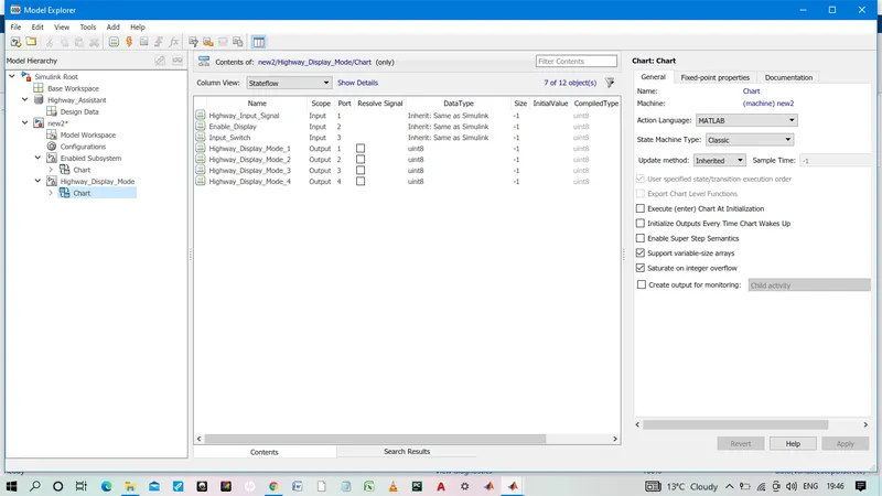
Output of this subsystem is connected to GOTO Block.That will use later as per requirement.
Requirement No 2 [Lane_DisplayUnit]:
Inputs to this particular subsystem are “Enable_Display”, “Input_Switch”, “Lane_Input_Signal”. These three input signals, when assigned to a particular value will give output signals of specific value. The output signals are “Lane_Display_Mode_1”, “Lane_Display_Mode_2”, “Lane_Display_Mode_3”, “Lane_Display_Mode_4”. The requirement must be implemented in the form of Stateflow logic.
|
Condition |
Action |
|
Lane_Input_Signal= 6 Enable_Display = off Input_Switch = on |
Lane_Display_Mode_1 = 132 Lane_Display_Mode_2 = 185 Lane_Display_Mode_3 = 54 Lane_Display_Mode_4 = 67 |
|
Lane_Input_Signal= 6 Enable_Display = on Input_Switch = on |
Lane_Display_Mode_1 = 127 Lane_Display_Mode_2 = 248 Lane_Display_Mode_3 = 186 Lane_Display_Mode_4 = 84 |
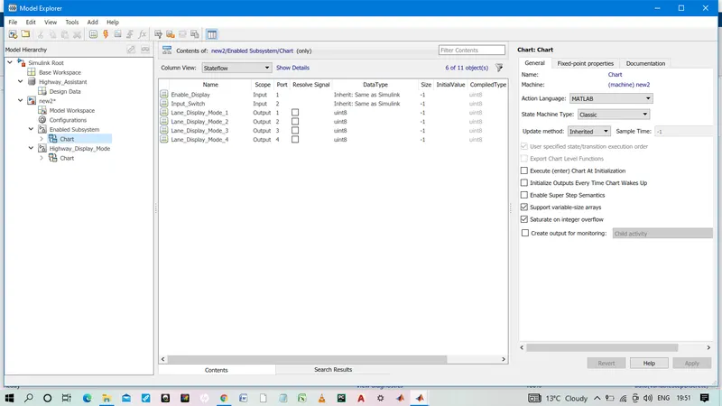
Created a subsytem with given input .Inside the subsytem , a chart is created with given input and outpput.Inside the chart, both condition is used by using state.
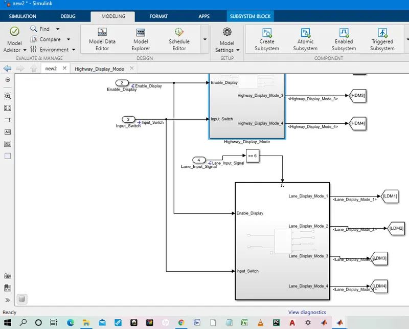
Output of this subsystem is connected to GOTO Block.That will use later as per requirement.
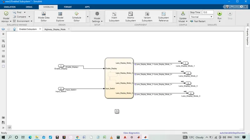
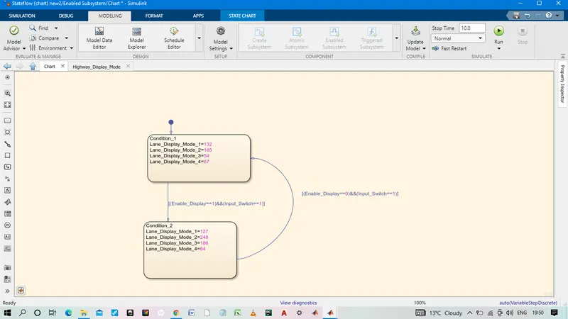
Input and outport port of chart is resolved as shown below.
Requirement No 3:
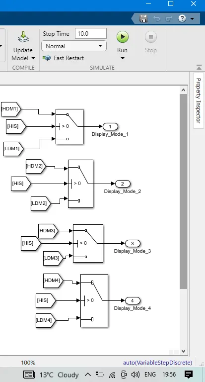
Signals coming from both subsystems “Highway_Display_Mode_1” & “Lane_Display_Mode_1” are given as inputs to a switch block which will have input signal “Highway_Input_Signal” given as 2nd input to the switch block. Corresponding output from this particular switch block is output signal “Display_Mode_1”.
Signals coming from both subsystems “Highway_Display_Mode_2” & “Lane_Display_Mode_2” are given as inputs to a switch block which will have input signal “Highway_Input_Signal” given as 2nd input to the switch block. Corresponding output from this particular switch block is output signal “Display_Mode_2”.
Signals coming from both subsystems “Highway_Display_Mode_3” & “Lane_Display_Mode_3” are given as inputs to a switch block which will have input signal “Highway_Input_Signal” given as 2nd input to the switch block. Corresponding output from this particular switch block is output signal “Display_Mode_3”.
Signals coming from both subsystems “Highway_Display_Mode_4” & “Lane_Display_Mode_4” are given as inputs to a switch block which will have input signal “Highway_Input_Signal” given as 2nd input to the switch block. Corresponding output from this particular switch block is output signal “Display_Mode_4”.
Step: Output of both system that is connected to GOTO Block.Requirement no 3 is completed by using From block as shown below.
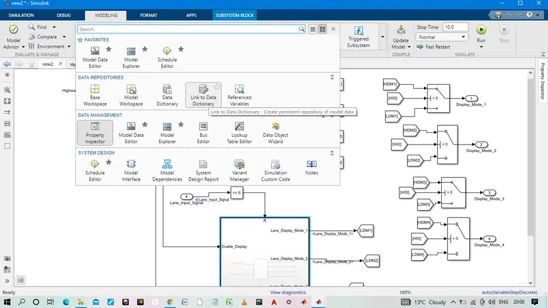
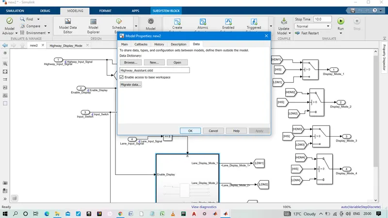
- Simulink Data Dictionary must be created for the model & must be linked to the model.
created data dictionary is linked to the model.
- Code Generation Profile must be Autosar Coder.
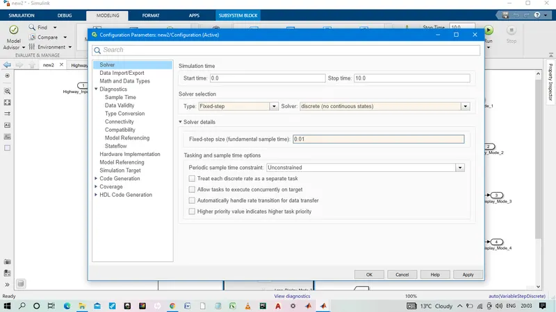
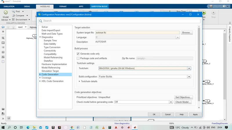
Model Advisor Report is mandatory .
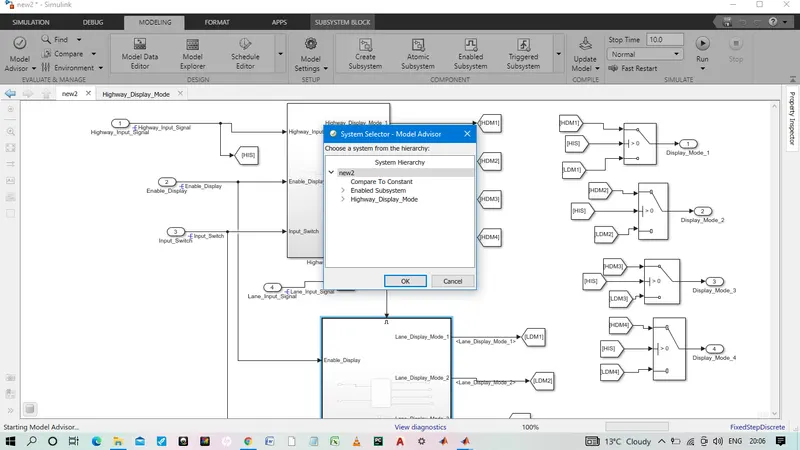
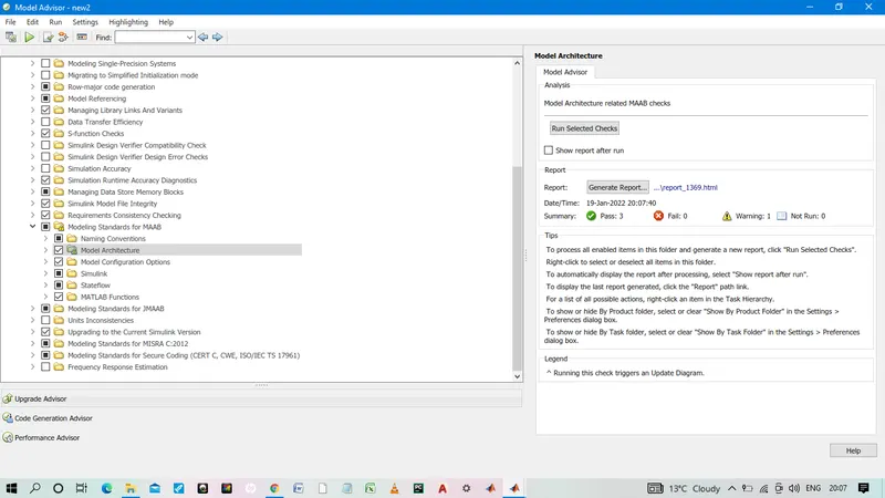
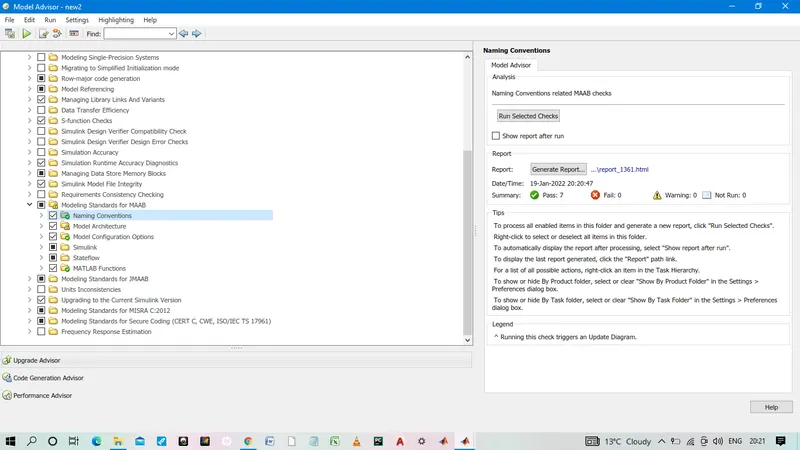
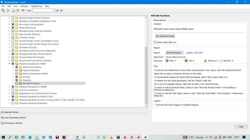
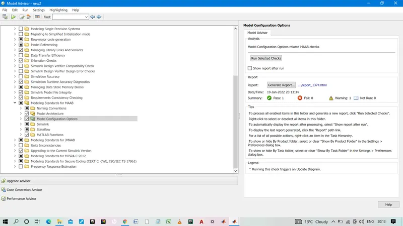
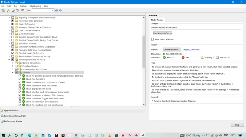
model advisory report is attached herewith sldd (data dictionary) and model.
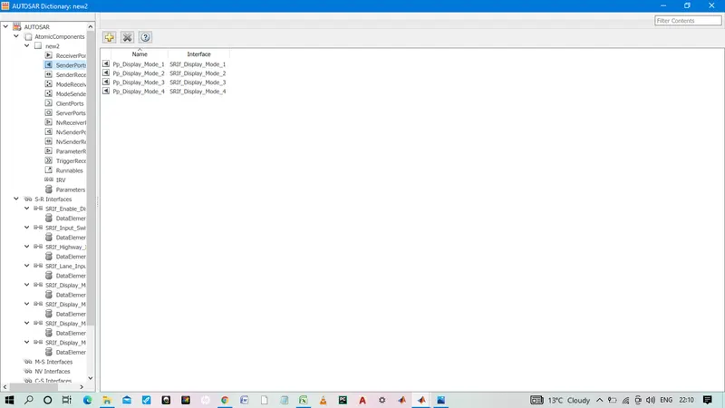
AUtosar mapping:
XML Mapping
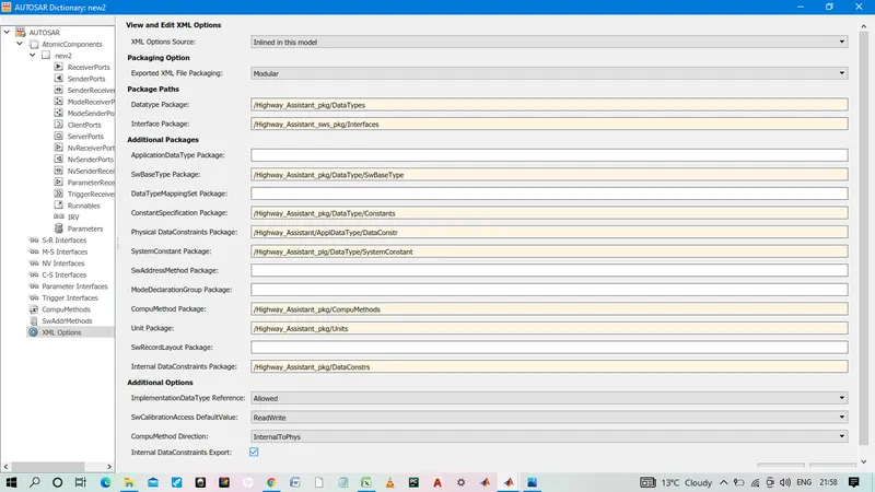
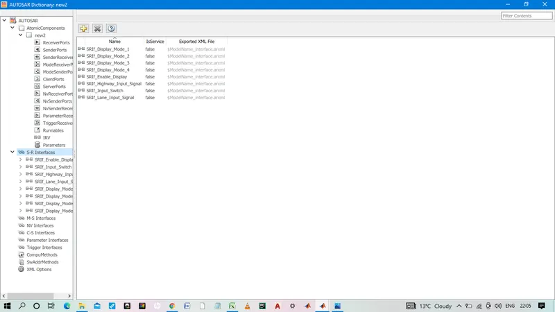
created sr interfaces for input and output with data element
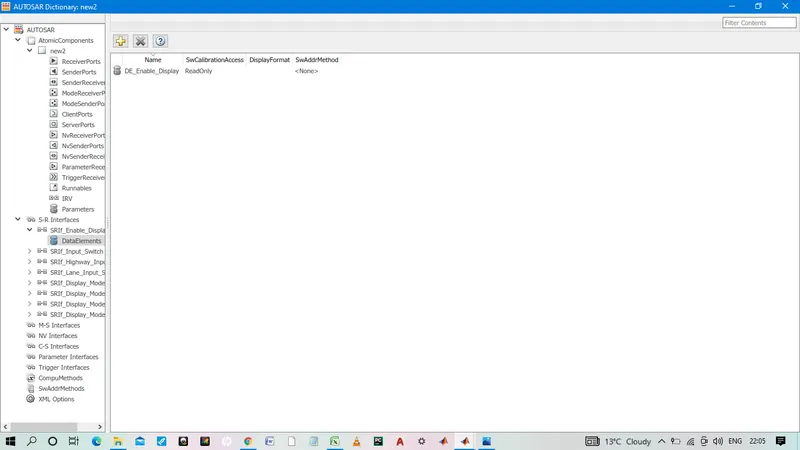
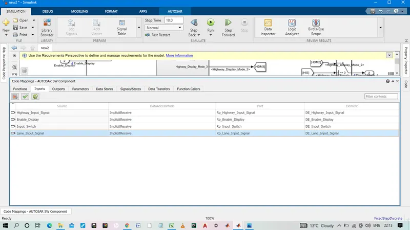
for input port
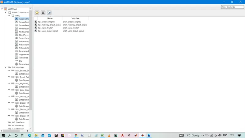
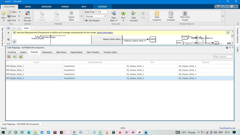
for output port
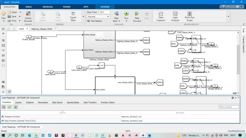
code mapping of autosar SW component
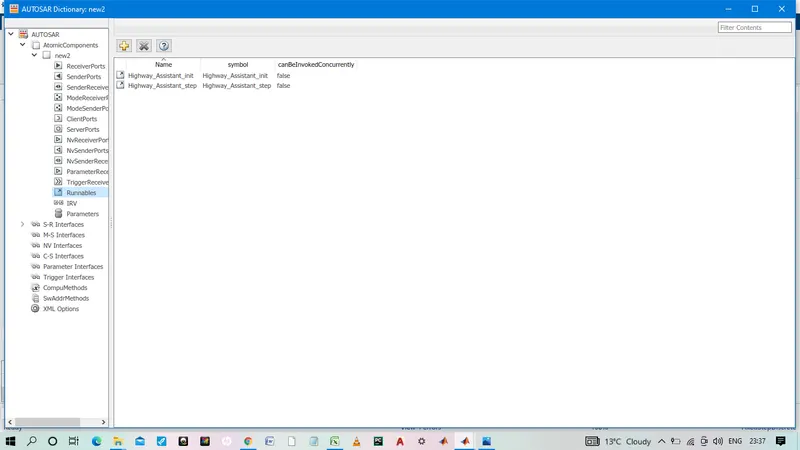
Runnables:
code generation:
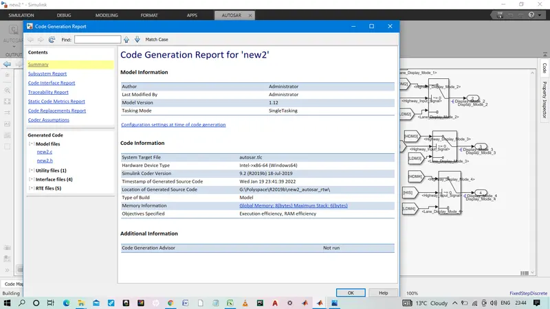
code:
new2.c
1 /*
2 * File: new2.c
3 *
4 * Code generated for Simulink model 'new2'.
5 *
6 * Model version : 1.12
7 * Simulink Coder version : 9.2 (R2019b) 18-Jul-2019
8 * C/C++ source code generated on : Wed Jan 19 23:41:39 2022
9 *
10 * Target selection: autosar.tlc
11 * Embedded hardware selection: Intel->x86-64 (Windows64)
12 * Code generation objectives:
13 * 1. Execution efficiency
14 * 2. RAM efficiency
15 * Validation result: Not run
16 */
17
18 #include "new2.h"
19
20 /* Named constants for Chart: '/Chart' */
21 #define IN_Condition_1 ((uint8)1U)
22 #define IN_Condition_2 ((uint8)2U)
23
24 /* Exported data definition */
25
26 /* Definition for custom storage class: Localizable */
27 static uint8 Lane_Display_Mode_1; /* '/Chart' */
28 static uint8 Lane_Display_Mode_2; /* '/Chart' */
29 static uint8 Lane_Display_Mode_3; /* '/Chart' */
30 static uint8 Lane_Display_Mode_4; /* '/Chart' */
31
32 /* Block signals and states (default storage) */
33 DW rtDW;
34
35 /* Model step function */
36 void Highway_Assistant_step(void)
37 {
38 uint8 rtb_Highway_Display_Mode_1;
39 uint8 rtb_Highway_Display_Mode_3;
40 sint32 tmp;
41
42 /* Chart: '/Chart' incorporates:
43 * Inport: '/Enable_Display'
44 * Inport: '/Highway_Input_Signal'
45 * Inport: '/Input_Switch'
46 */
47 if (rtDW.is_active_c3_new2 == 0U) {
48 rtDW.is_active_c3_new2 = 1U;
49 rtDW.is_c3_new2 = IN_Condition_1;
50 rtb_Highway_Display_Mode_1 = 232U;
51 rtb_Highway_Display_Mode_3 = 41U;
52 } else if (rtDW.is_c3_new2 == IN_Condition_1) {
53 if ((Rte_IRead_Highway_Assistant_step_Rp_Highway_Input_Signal_DE_Highway_Input_Signal
54 () == 1) &&
55 (Rte_IRead_Highway_Assistant_step_Rp_Enable_Display_DE_Enable_Display() ==
56 1) && (Rte_IRead_Highway_Assistant_step_Rp_Input_Switch_DE_Input_Switch
57 () == 1)) {
58 rtDW.is_c3_new2 = IN_Condition_2;
59 rtb_Highway_Display_Mode_1 = 213U;
60 rtb_Highway_Display_Mode_3 = 9U;
61 } else {
62 rtb_Highway_Display_Mode_1 = 232U;
63 rtb_Highway_Display_Mode_3 = 41U;
64 }
65 } else {
66 /* case IN_Condition_2: */
67 if ((Rte_IRead_Highway_Assistant_step_Rp_Highway_Input_Signal_DE_Highway_Input_Signal
68 () == 1) &&
69 (Rte_IRead_Highway_Assistant_step_Rp_Enable_Display_DE_Enable_Display() ==
70 0) && (Rte_IRead_Highway_Assistant_step_Rp_Input_Switch_DE_Input_Switch
71 () == 1)) {
72 rtDW.is_c3_new2 = IN_Condition_1;
73 rtb_Highway_Display_Mode_1 = 232U;
74 rtb_Highway_Display_Mode_3 = 41U;
75 } else {
76 rtb_Highway_Display_Mode_1 = 213U;
77 rtb_Highway_Display_Mode_3 = 9U;
78 }
79 }
80
81 /* End of Chart: '/Chart' */
82
83 /* Outputs for Enabled SubSystem: '/Enabled_Subsystem' incorporates:
84 * EnablePort: '/Enable'
85 */
86 /* RelationalOperator: '/Compare' incorporates:
87 * Constant: '/Constant'
88 * Inport: '/Lane_Input_Signal'
89 */
90 if (Rte_IRead_Highway_Assistant_step_Rp_Lane_Input_Signal_DE_Lane_Input_Signal
91 () == 6) {
92 /* Chart: '/Chart' incorporates:
93 * Inport: '/Enable_Display'
94 * Inport: '/Input_Switch'
95 */
96 if (rtDW.is_active_c1_new2 == 0U) {
97 rtDW.is_active_c1_new2 = 1U;
98 rtDW.is_c1_new2 = IN_Condition_1;
99 Lane_Display_Mode_1 = 132U;
100 Lane_Display_Mode_2 = 185U;
101 Lane_Display_Mode_3 = 54U;
102 Lane_Display_Mode_4 = 67U;
103 } else if (rtDW.is_c1_new2 == IN_Condition_1) {
104 if ((Rte_IRead_Highway_Assistant_step_Rp_Enable_Display_DE_Enable_Display()
105 == 1) &&
106 (Rte_IRead_Highway_Assistant_step_Rp_Input_Switch_DE_Input_Switch() ==
107 1)) {
108 rtDW.is_c1_new2 = IN_Condition_2;
109 Lane_Display_Mode_1 = 127U;
110 Lane_Display_Mode_2 = 248U;
111 Lane_Display_Mode_3 = 186U;
112 Lane_Display_Mode_4 = 84U;
113 } else {
114 Lane_Display_Mode_1 = 132U;
115 Lane_Display_Mode_2 = 185U;
116 Lane_Display_Mode_3 = 54U;
117 Lane_Display_Mode_4 = 67U;
118 }
119 } else {
120 /* case IN_Condition_2: */
121 if ((Rte_IRead_Highway_Assistant_step_Rp_Enable_Display_DE_Enable_Display()
122 == 0) &&
123 (Rte_IRead_Highway_Assistant_step_Rp_Input_Switch_DE_Input_Switch() ==
124 1)) {
125 rtDW.is_c1_new2 = IN_Condition_1;
126 Lane_Display_Mode_1 = 132U;
127 Lane_Display_Mode_2 = 185U;
128 Lane_Display_Mode_3 = 54U;
129 Lane_Display_Mode_4 = 67U;
130 } else {
131 Lane_Display_Mode_1 = 127U;
132 Lane_Display_Mode_2 = 248U;
133 Lane_Display_Mode_3 = 186U;
134 Lane_Display_Mode_4 = 84U;
135 }
136 }
137
138 /* End of Chart: '/Chart' */
139 }
140
141 /* End of RelationalOperator: '/Compare' */
142 /* End of Outputs for SubSystem: '/Enabled_Subsystem' */
143
144 /* Switch: '/Switch' incorporates:
145 * Inport: '/Highway_Input_Signal'
146 * Switch: '/Switch1'
147 * Switch: '/Switch2'
148 */
149 tmp =
150 Rte_IRead_Highway_Assistant_step_Rp_Highway_Input_Signal_DE_Highway_Input_Signal
151 ();
152 if (tmp != 0) {
153 /* Outport: '/Display_Mode_1' */
154 Rte_IWrite_Highway_Assistant_step_Pp_Display_Mode_1_DE_Display_Mode_1
155 (rtb_Highway_Display_Mode_1);
156 rtb_Highway_Display_Mode_1 = 183U;
157 } else {
158 /* Outport: '/Display_Mode_1' */
159 Rte_IWrite_Highway_Assistant_step_Pp_Display_Mode_1_DE_Display_Mode_1
160 (Lane_Display_Mode_1);
161 rtb_Highway_Display_Mode_1 = Lane_Display_Mode_2;
162 }
163
164 /* End of Switch: '/Switch' */
165
166 /* Outport: '/Display_Mode_2' */
167 Rte_IWrite_Highway_Assistant_step_Pp_Display_Mode_2_DE_Display_Mode_2
168 (rtb_Highway_Display_Mode_1);
169
170 /* Switch: '/Switch2' incorporates:
171 * Switch: '/Switch3'
172 */
173 if (tmp != 0) {
174 /* Outport: '/Display_Mode_3' */
175 Rte_IWrite_Highway_Assistant_step_Pp_Display_Mode_3_DE_Display_Mode_3
176 (rtb_Highway_Display_Mode_3);
177 rtb_Highway_Display_Mode_1 = 94U;
178 } else {
179 /* Outport: '/Display_Mode_3' */
180 Rte_IWrite_Highway_Assistant_step_Pp_Display_Mode_3_DE_Display_Mode_3
181 (Lane_Display_Mode_3);
182 rtb_Highway_Display_Mode_1 = Lane_Display_Mode_4;
183 }
184
185 /* Outport: '/Display_Mode_4' */
186 Rte_IWrite_Highway_Assistant_step_Pp_Display_Mode_4_DE_Display_Mode_4
187 (rtb_Highway_Display_Mode_1);
188 }
189
190 /* Model initialize function */
191 void Highway_Assistant_init(void)
192 {
193 /* (no initialization code required) */
194 }
195
196 /*
197 * File trailer for generated code.
198 *
199 * [EOF]
200 */
201
new2.h
1 /*
2 * File: new2.h
3 *
4 * Code generated for Simulink model 'new2'.
5 *
6 * Model version : 1.12
7 * Simulink Coder version : 9.2 (R2019b) 18-Jul-2019
8 * C/C++ source code generated on : Wed Jan 19 23:41:39 2022
9 *
10 * Target selection: autosar.tlc
11 * Embedded hardware selection: Intel->x86-64 (Windows64)
12 * Code generation objectives:
13 * 1. Execution efficiency
14 * 2. RAM efficiency
15 * Validation result: Not run
16 */
17
18 #ifndef RTW_HEADER_new2_h_
19 #define RTW_HEADER_new2_h_
20 #ifndef new2_COMMON_INCLUDES_
21 # define new2_COMMON_INCLUDES_
22 #include "rtwtypes.h"
23 #include "Rte_new2.h"
24 #endif /* new2_COMMON_INCLUDES_ */
25
26 /* Macros for accessing real-time model data structure */
27
28 /* Block signals and states (default storage) for system '' */
29 typedef struct tag_DW {
30 uint8 is_active_c3_new2; /* '/Chart' */
31 uint8 is_c3_new2; /* '/Chart' */
32 uint8 is_active_c1_new2; /* '/Chart' */
33 uint8 is_c1_new2; /* '/Chart' */
34 } DW;
35
36 /* Block signals and states (default storage) */
37 extern DW rtDW;
38
39 /*-
40 * The generated code includes comments that allow you to trace directly
41 * back to the appropriate location in the model. The basic format
42 * is /block_name, where system is the system number (uniquely
43 * assigned by Simulink) and block_name is the name of the block.
44 *
45 * Use the MATLAB hilite_system command to trace the generated code back
46 * to the model. For example,
47 *
48 * hilite_system('') - opens system 3
49 * hilite_system('/Kp') - opens and selects block Kp which resides in S3
50 *
51 * Here is the system hierarchy for this model
52 *
53 * '' : 'new2'
54 * '' : 'new2/Compare To Constant'
55 * '' : 'new2/Enabled_Subsystem'
56 * '' : 'new2/Highway_Display_Mode'
57 * '' : 'new2/Enabled_Subsystem/Chart'
58 * '' : 'new2/Highway_Display_Mode/Chart'
59 */
60 #endif /* RTW_HEADER_new2_h_ */
61
62 /*
63 * File trailer for generated code.
64 *
65 * [EOF]
66 */
67
File: rtwtypes.h
1 /*
2 * File: rtwtypes.h
3 *
4 * Code generated for Simulink model 'new2'.
5 *
6 * Model version : 1.12
7 * Simulink Coder version : 9.2 (R2019b) 18-Jul-2019
8 * C/C++ source code generated on : Wed Jan 19 23:41:39 2022
9 *
10 * Target selection: autosar.tlc
11 * Embedded hardware selection: Intel->x86-64 (Windows64)
12 * Code generation objectives:
13 * 1. Execution efficiency
14 * 2. RAM efficiency
15 * Validation result: Not run
16 */
17
18 #ifndef RTWTYPES_H
19 #define RTWTYPES_H
20
21 /* Logical type definitions */
22 #if (!defined(__cplusplus))
23 # ifndef false
24 # define false (0U)
25 # endif
26
27 # ifndef true
28 # define true (1U)
29 # endif
30 #endif
31
32 /*=======================================================================*
33 * Target hardware information
34 * Device type: Intel->x86-64 (Windows64)
35 * Number of bits: char: 8 short: 16 int: 32
36 * long: 32 long long: 64
37 * native word size: 64
38 * Byte ordering: LittleEndian
39 * Signed integer division rounds to: Zero
40 * Shift right on a signed integer as arithmetic shift: on
41 *=======================================================================*/
42
43 /*=======================================================================*
44 * Fixed width word size data types: *
45 * int8_T, int16_T, int32_T - signed 8, 16, or 32 bit integers *
46 * uint8_T, uint16_T, uint32_T - unsigned 8, 16, or 32 bit integers *
47 *=======================================================================*/
48 typedef signed char int8_T;
49 typedef unsigned char uint8_T;
50 typedef short int16_T;
51 typedef unsigned short uint16_T;
52 typedef int int32_T;
53 typedef unsigned int uint32_T;
54 typedef long long int64_T;
55 typedef unsigned long long uint64_T;
56
57 /*===========================================================================*
58 * Generic type definitions: boolean_T, char_T, byte_T, int_T, uint_T, *
59 * ulong_T, ulonglong_T. *
60 *===========================================================================*/
61 typedef unsigned char boolean_T;
62 typedef int int_T;
63 typedef unsigned int uint_T;
64 typedef unsigned long ulong_T;
65 typedef unsigned long long ulonglong_T;
66 typedef char char_T;
67 typedef unsigned char uchar_T;
68 typedef char_T byte_T;
69
70 /*=======================================================================*
71 * Min and Max: *
72 * int8_T, int16_T, int32_T - signed 8, 16, or 32 bit integers *
73 * uint8_T, uint16_T, uint32_T - unsigned 8, 16, or 32 bit integers *
74 *=======================================================================*/
75 #define MAX_int8_T ((int8_T)(127))
76 #define MIN_int8_T ((int8_T)(-128))
77 #define MAX_uint8_T ((uint8_T)(255U))
78 #define MAX_int16_T ((int16_T)(32767))
79 #define MIN_int16_T ((int16_T)(-32768))
80 #define MAX_uint16_T ((uint16_T)(65535U))
81 #define MAX_int32_T ((int32_T)(2147483647))
82 #define MIN_int32_T ((int32_T)(-2147483647-1))
83 #define MAX_uint32_T ((uint32_T)(0xFFFFFFFFU))
84 #define MAX_int64_T ((int64_T)(9223372036854775807LL))
85 #define MIN_int64_T ((int64_T)(-9223372036854775807LL-1LL))
86 #define MAX_uint64_T ((uint64_T)(0xFFFFFFFFFFFFFFFFULL))
87
88 /* Block D-Work pointer type */
89 typedef void * pointer_T;
90
91 /* Include definitions for AUTOSAR Standard and Platform data types. */
92 #include "Std_Types.h"
93 #endif /* RTWTYPES_H */
94
95 /*
96 * File trailer for generated code.
97 *
98 * [EOF]
99 */
100
File: new2_component.arxml
1
2
9
10
11
12 Components
13
14
15 new2
16
17
18 Rp_Enable_Display
19
20
21 /Highway_Assistant_sws_pkg/Interfaces/SRIf_Enable_Display/DE_Enable_Display
22 NONE
23 false
24 0
25 false
26 false
27 NONE
28
29
30 DefaultInitValue_UInt8
31 0
32
33
34
35
36 /Highway_Assistant_sws_pkg/Interfaces/SRIf_Enable_Display
37
38
39 Rp_Input_Switch
40
41
42 /Highway_Assistant_sws_pkg/Interfaces/SRIf_Input_Switch/DE_Input_Switch
43 NONE
44 false
45 0
46 false
47 false
48 NONE
49
50
51 DefaultInitValue_UInt8
52 0
53
54
55
56
57 /Highway_Assistant_sws_pkg/Interfaces/SRIf_Input_Switch
58
59
60 Rp_Highway_Input_Signal
61
62
63 /Highway_Assistant_sws_pkg/Interfaces/SRIf_Highway_Input_Signal/DE_Highway_Input_Signal
64 NONE
65 false
66 0
67 false
68 false
69 NONE
70
71
72 DefaultInitValue_UInt8
73 0
74
75
76
77
78 /Highway_Assistant_sws_pkg/Interfaces/SRIf_Highway_Input_Signal
79
80
81 Rp_Lane_Input_Signal
82
83
84 /Highway_Assistant_sws_pkg/Interfaces/SRIf_Lane_Input_Signal/DE_Lane_Input_Signal
85 NONE
86 false
87 0
88 false
89 false
90 NONE
91
92
93 DefaultInitValue_UInt8
94 0
95
96
97
98
99 /Highway_Assistant_sws_pkg/Interfaces/SRIf_Lane_Input_Signal
100
101
102 Pp_Display_Mode_1
103
104
105 /Highway_Assistant_sws_pkg/Interfaces/SRIf_Display_Mode_1/DE_Display_Mode_1
106 NONE
107 false
108
109
110 DefaultInitValue_UInt8
111 0
112
113
114
115
116 /Highway_Assistant_sws_pkg/Interfaces/SRIf_Display_Mode_1
117
118
119 Pp_Display_Mode_2
120
121
122 /Highway_Assistant_sws_pkg/Interfaces/SRIf_Display_Mode_2/DE_Display_Mode_2
123 NONE
124 false
125
126
127 DefaultInitValue_UInt8
128 0
129
130
131
132
133 /Highway_Assistant_sws_pkg/Interfaces/SRIf_Display_Mode_2
134
135
136 Pp_Display_Mode_3
137
138
139 /Highway_Assistant_sws_pkg/Interfaces/SRIf_Display_Mode_3/DE_Display_Mode_3
140 NONE
141 false
142
143
144 DefaultInitValue_UInt8
145 0
146
147
148
149
150 /Highway_Assistant_sws_pkg/Interfaces/SRIf_Display_Mode_3
151
152
153 Pp_Display_Mode_4
154
155
156 /Highway_Assistant_sws_pkg/Interfaces/SRIf_Display_Mode_4/DE_Display_Mode_4
157 NONE
158 false
159
160
161 DefaultInitValue_UInt8
162 0
163
164
165
166
167 /Highway_Assistant_sws_pkg/Interfaces/SRIf_Display_Mode_4
168
169
170
171
172 new2_IB
173
174
175 Highway_Assistant_initevent
176 /Components/new2/new2_IB/Highway_Assistant_init
177
178
179 Highway_Assistant_stepevent
180 /Components/new2/new2_IB/Highway_Assistant_step
181 0.01
182
183
184 NO-SUPPORT
185
186
187 Highway_Assistant_init
188 0
189 false
190 Highway_Assistant_init
191
192
193 Highway_Assistant_step
194 0
195 false
196
197
198 IN_Rp_Enable_Display_DE_Enable_Display
199
200
201 /Components/new2/Rp_Enable_Display
202 /Highway_Assistant_sws_pkg/Interfaces/SRIf_Enable_Display/DE_Enable_Display
203
204
205
206
207 IN_Rp_Highway_Input_Signal_DE_Highway_Input_Signal
208
209
210 /Components/new2/Rp_Highway_Input_Signal
211 /Highway_Assistant_sws_pkg/Interfaces/SRIf_Highway_Input_Signal/DE_Highway_Input_Signal
212
213
214
215
216 IN_Rp_Input_Switch_DE_Input_Switch
217
218
219 /Components/new2/Rp_Input_Switch
220 /Highway_Assistant_sws_pkg/Interfaces/SRIf_Input_Switch/DE_Input_Switch
221
222
223
224
225 IN_Rp_Lane_Input_Signal_DE_Lane_Input_Signal
226
227
228 /Components/new2/Rp_Lane_Input_Signal
229 /Highway_Assistant_sws_pkg/Interfaces/SRIf_Lane_Input_Signal/DE_Lane_Input_Signal
230
231
232
233
234
235
236 OUT_Pp_Display_Mode_1_DE_Display_Mode_1
237
238
239 /Components/new2/Pp_Display_Mode_1
240 /Highway_Assistant_sws_pkg/Interfaces/SRIf_Display_Mode_1/DE_Display_Mode_1
241
242
243
244
245 OUT_Pp_Display_Mode_2_DE_Display_Mode_2
246
247
248 /Components/new2/Pp_Display_Mode_2
249 /Highway_Assistant_sws_pkg/Interfaces/SRIf_Display_Mode_2/DE_Display_Mode_2
250
251
252
253
254 OUT_Pp_Display_Mode_3_DE_Display_Mode_3
255
256
257 /Components/new2/Pp_Display_Mode_3
258 /Highway_Assistant_sws_pkg/Interfaces/SRIf_Display_Mode_3/DE_Display_Mode_3
259
260
261
262
263 OUT_Pp_Display_Mode_4_DE_Display_Mode_4
264
265
266 /Components/new2/Pp_Display_Mode_4
267 /Highway_Assistant_sws_pkg/Interfaces/SRIf_Display_Mode_4/DE_Display_Mode_4
268
269
270
271
272 Highway_Assistant_step
273
274
275 false
276
277
278
279
280
281
282
283
File: new2_datatype.arxml
1
2
9
10
11
12 Highway_Assistant_pkg
13
14
15 DataConstrs
16
17
18 DC_UInt8
19
20
21
22 0
23 255
24
25
26
27
28
29
30
31 DataType
32
33
34 SwBaseType
35
36
37 uint8
38 FIXED_LENGTH
39 8
40 NONE
41 uint8
42
43
44
45
46
47
48 DataTypes
49
50
51 UInt8
52 VALUE
53
54
55
56 /Highway_Assistant_pkg/DataType/SwBaseType/uint8
57 /Highway_Assistant_pkg/DataConstrs/DC_UInt8
58
59
60
61
62
63
64
65
66
67
68
File: new2_implementation.arxml
1
2
9
10
11
12 Components
13
14
15
16 SwcImplementations
17
18
19 new2_Impl
20
21
22 Code
23
24
25 new2_c
26 SWSRC
27
28
29 new2_h
30 SWHDR
31
32
33 rtwtypes_h
34 SWHDR
35
36
37
38
39 C
40
41 RsrcCons_new2
42
43 1.12.1
44 Embedded Coder 7.3 (R2019b) 18-Jul-2019
45 0
46 /Components/new2/new2_IB
47
48
49
50
51
52
53
54
File: new2_interface.arxml
1
2
9
10
11
12 Highway_Assistant_sws_pkg
13
14
15 Interfaces
16
17
18 SRIf_Enable_Display
19 false
20
21
22 DE_Enable_Display
23 VALUE
24
25
26
27 READ-ONLY
28 STANDARD
29
30
31
32 /Highway_Assistant_pkg/DataTypes/UInt8
33
34
35
36
37 SRIf_Input_Switch
38 false
39
40
41 DE_Input_Switch
42 VALUE
43
44
45
46 READ-ONLY
47 STANDARD
48
49
50
51 /Highway_Assistant_pkg/DataTypes/UInt8
52
53
54
55
56 SRIf_Highway_Input_Signal
57 false
58
59
60 DE_Highway_Input_Signal
61 VALUE
62
63
64
65 READ-ONLY
66 STANDARD
67
68
69
70 /Highway_Assistant_pkg/DataTypes/UInt8
71
72
73
74
75 SRIf_Lane_Input_Signal
76 false
77
78
79 DE_Lane_Input_Signal
80 VALUE
81
82
83
84 READ-ONLY
85 STANDARD
86
87
88
89 /Highway_Assistant_pkg/DataTypes/UInt8
90
91
92
93
94 SRIf_Display_Mode_1
95 false
96
97
98 DE_Display_Mode_1
99 VALUE
100
101
102
103 READ-ONLY
104 STANDARD
105
106
107
108 /Highway_Assistant_pkg/DataTypes/UInt8
109
110
111
112
113 SRIf_Display_Mode_2
114 false
115
116
117 DE_Display_Mode_2
118 VALUE
119
120
121
122 READ-ONLY
123 STANDARD
124
125
126
127 /Highway_Assistant_pkg/DataTypes/UInt8
128
129
130
131
132 SRIf_Display_Mode_3
133 false
134
135
136 DE_Display_Mode_3
137 VALUE
138
139
140
141 READ-ONLY
142 STANDARD
143
144
145
146 /Highway_Assistant_pkg/DataTypes/UInt8
147
148
149
150
151 SRIf_Display_Mode_4
152 false
153
154
155 DE_Display_Mode_4
156 VALUE
157
158
159
160 READ-ONLY
161 STANDARD
162
163
164
165 /Highway_Assistant_pkg/DataTypes/UInt8
166
167
168
169
170
171
172
173
174
175
File: Compiler.h
1 /* Copyright 2018 The MathWorks, Inc. */
2
3 /*
4 * File: Compiler.h
5 *
6 * Compiler Abstraction Macros
7 *
8 * This header file specifies macros for the abstraction of compiler specific
9 * keywords used for addressing data and code within declarations and
10 * definitions. This is used to overcome problems caused by the limited 16 bit
11 * addressing range. For SIL/PIL macros behave as identity operators.
12 *
13 * Note that this file should be replaced with an appropriate RTE file when
14 * deploying the generated code outside of Simulink.
15 */
16
17 #ifndef Compiler_h
18 #define Compiler_h
19
20 /* Compiler abstraction macros */
21 #define FUNC(type, memclass) type
22 #define P2VAR(ptrtype, memclass, ptrclass) ptrtype *
23 #define P2CONST(ptrtype, memclass, ptrclass) const ptrtype *
24 #define CONSTP2VAR(ptrtype, memclass, ptrclass) ptrtype * const
25 #define CONSTP2CONST(ptrtype, memclass, ptrclass) const ptrtype * const
26 #define CONST(consttype, memclass) const consttype
27 #define VAR( type, memclass ) type
28
29 #endif /* Compiler_h */
30
File: Platform_Types.h
1 /* Copyright 2018 The MathWorks, Inc. */
2
3 /*
4 * File: Platform_Types.h
5 *
6 * Definitions for AUTOSAR platform types
7 *
8 * This file contains stub implementations of the AUTOSAR Platform Types.
9 * The stub implementations can be used for testing the generated code in
10 * Simulink, for example, in SIL/PIL simulations of the component under
11 * test. Note that this file should be replaced with an appropriate RTE
12 * file when deploying the generated code outside of Simulink.
13 */
14
15 #ifndef PLATFORM_TYPES_H
16 #define PLATFORM_TYPES_H
17
18 /* Define AUTOSAR platform types */
19 typedef boolean_T boolean;
20 typedef int16_T sint16;
21 typedef int32_T sint32;
22 typedef int8_T sint8;
23 typedef uint16_T uint16;
24 typedef uint32_T uint32;
25 typedef uint8_T uint8;
26 typedef float float32;
27 typedef double float64;
28
29 /* if target supports long long, rtwtypes.h will define MAX_uint64_T */
30 #ifdef MAX_uint64_T
31 typedef int64_T sint64;
32 typedef uint64_T uint64;
33 #endif
34
35 /* Define AUTOSAR standard primitive types */
36 typedef boolean Boolean;
37 typedef uint8 Char8;
38 typedef sint16 SInt16;
39 typedef sint32 SInt32;
40 typedef sint8 SInt4;
41 typedef sint8 SInt8;
42 typedef uint16 UInt16;
43 typedef uint32 UInt32;
44 typedef uint8 UInt4;
45 typedef uint8 UInt8;
46 typedef float64 Double;
47 typedef float64 Double_with_Nan;
48 typedef float32 Float;
49 typedef float32 Float_with_NaN;
50 #ifdef MAX_uint64_T
51 typedef int64_T SInt64;
52 typedef uint64_T UInt64;
53 #endif
54
55
56 #endif /* PLATFORM_TYPES_H */
57
File: Rte_Type.h
1 /* This file contains stub implementations of the AUTOSAR RTE functions.
2 The stub implementations can be used for testing the generated code in
3 Simulink, for example, in SIL/PIL simulations of the component under
4 test. Note that this file should be replaced with an appropriate RTE
5 file when deploying the generated code outside of Simulink.
6
7 This file is generated for:
8 Atomic software component: "new2"
9 ARXML schema: "4.3"
10 File generated on: "19-Jan-2022 23:42:20" */
11
12 #ifndef Rte_Type_h
13 #define Rte_Type_h
14 #include "rtwtypes.h"
15 #include "Std_Types.h"
16
17 /* AUTOSAR RTE Status Types */
18 #ifndef RTE_E_OK
19 #define RTE_E_OK (0x00)
20 #endif
21
22 #ifndef RTE_E_LOST_DATA
23 #define RTE_E_LOST_DATA (0x40)
24 #endif
25
26 #ifndef RTE_E_LIMIT
27 #define RTE_E_LIMIT (0x82)
28 #endif
29
30 #ifndef E2E_E_OK
31 #define E2E_E_OK (0x00)
32 #endif
33
34 #ifndef E2EPW_STATUS_OK
35 #define E2EPW_STATUS_OK (0x00)
36 #endif
37
38 #ifndef E2EPW_STATUS_OKSOMELOST
39 #define E2EPW_STATUS_OKSOMELOST (0x20)
40 #endif
41
42 /* AUTOSAR Implementation data types, specific to software component */
43 typedef void* Rte_Instance;
44
45 #endif
46
File: Rte_new2.h
1 /* This file contains stub implementations of the AUTOSAR RTE functions.
2 The stub implementations can be used for testing the generated code in
3 Simulink, for example, in SIL/PIL simulations of the component under
4 test. Note that this file should be replaced with an appropriate RTE
5 file when deploying the generated code outside of Simulink.
6
7 This file is generated for:
8 Atomic software component: "new2"
9 ARXML schema: "4.3"
10 File generated on: "19-Jan-2022 23:42:20" */
11
12 #ifndef Rte_new2_h
13 #define Rte_new2_h
14 #include "Rte_Type.h"
15 #include "Compiler.h"
16
17 /* Data access functions */
18 #define Rte_IRead_Highway_Assistant_step_Rp_Enable_Display_DE_Enable_Display Rte_IRead_new2_Highway_Assistant_step_Rp_Enable_Display_DE_Enable_Display
19
20 UInt8 Rte_IRead_Highway_Assistant_step_Rp_Enable_Display_DE_Enable_Display(void);
21
22 #define Rte_IRead_Highway_Assistant_step_Rp_Highway_Input_Signal_DE_Highway_Input_Signal Rte_IRead_new2_Highway_Assistant_step_Rp_Highway_Input_Signal_DE_Highway_Input_Signal
23
24 UInt8
25 Rte_IRead_Highway_Assistant_step_Rp_Highway_Input_Signal_DE_Highway_Input_Signal
26 (void);
27
28 #define Rte_IRead_Highway_Assistant_step_Rp_Input_Switch_DE_Input_Switch Rte_IRead_new2_Highway_Assistant_step_Rp_Input_Switch_DE_Input_Switch
29
30 UInt8 Rte_IRead_Highway_Assistant_step_Rp_Input_Switch_DE_Input_Switch(void);
31
32 #define Rte_IRead_Highway_Assistant_step_Rp_Lane_Input_Signal_DE_Lane_Input_Signal Rte_IRead_new2_Highway_Assistant_step_Rp_Lane_Input_Signal_DE_Lane_Input_Signal
33
34 UInt8 Rte_IRead_Highway_Assistant_step_Rp_Lane_Input_Signal_DE_Lane_Input_Signal
35 (void);
36
37 #define Rte_IWrite_Highway_Assistant_step_Pp_Display_Mode_1_DE_Display_Mode_1 Rte_IWrite_new2_Highway_Assistant_step_Pp_Display_Mode_1_DE_Display_Mode_1
38
39 void Rte_IWrite_Highway_Assistant_step_Pp_Display_Mode_1_DE_Display_Mode_1(UInt8
40 u);
41
42 #define Rte_IWriteRef_Highway_Assistant_step_Pp_Display_Mode_1_DE_Display_Mode_1 Rte_IWriteRef_new2_Highway_Assistant_step_Pp_Display_Mode_1_DE_Display_Mode_1
43
44 UInt8* Rte_IWriteRef_Highway_Assistant_step_Pp_Display_Mode_1_DE_Display_Mode_1
45 (void);
46
47 #define Rte_IWrite_Highway_Assistant_step_Pp_Display_Mode_2_DE_Display_Mode_2 Rte_IWrite_new2_Highway_Assistant_step_Pp_Display_Mode_2_DE_Display_Mode_2
48
49 void Rte_IWrite_Highway_Assistant_step_Pp_Display_Mode_2_DE_Display_Mode_2(UInt8
50 u);
51
52 #define Rte_IWriteRef_Highway_Assistant_step_Pp_Display_Mode_2_DE_Display_Mode_2 Rte_IWriteRef_new2_Highway_Assistant_step_Pp_Display_Mode_2_DE_Display_Mode_2
53
54 UInt8* Rte_IWriteRef_Highway_Assistant_step_Pp_Display_Mode_2_DE_Display_Mode_2
55 (void);
56
57 #define Rte_IWrite_Highway_Assistant_step_Pp_Display_Mode_3_DE_Display_Mode_3 Rte_IWrite_new2_Highway_Assistant_step_Pp_Display_Mode_3_DE_Display_Mode_3
58
59 void Rte_IWrite_Highway_Assistant_step_Pp_Display_Mode_3_DE_Display_Mode_3(UInt8
60 u);
61
62 #define Rte_IWriteRef_Highway_Assistant_step_Pp_Display_Mode_3_DE_Display_Mode_3 Rte_IWriteRef_new2_Highway_Assistant_step_Pp_Display_Mode_3_DE_Display_Mode_3
63
64 UInt8* Rte_IWriteRef_Highway_Assistant_step_Pp_Display_Mode_3_DE_Display_Mode_3
65 (void);
66
67 #define Rte_IWrite_Highway_Assistant_step_Pp_Display_Mode_4_DE_Display_Mode_4 Rte_IWrite_new2_Highway_Assistant_step_Pp_Display_Mode_4_DE_Display_Mode_4
68
69 void Rte_IWrite_Highway_Assistant_step_Pp_Display_Mode_4_DE_Display_Mode_4(UInt8
70 u);
71
72 #define Rte_IWriteRef_Highway_Assistant_step_Pp_Display_Mode_4_DE_Display_Mode_4 Rte_IWriteRef_new2_Highway_Assistant_step_Pp_Display_Mode_4_DE_Display_Mode_4
73
74 UInt8* Rte_IWriteRef_Highway_Assistant_step_Pp_Display_Mode_4_DE_Display_Mode_4
75 (void);
76
77 /* Entry point functions */
78 extern FUNC(void, new2_CODE) Highway_Assistant_init(void);
79 extern FUNC(void, new2_CODE) Highway_Assistant_step(void);
80
81 #endif
82
File: Std_Types.h
1 /* Copyright 2018 The MathWorks, Inc. */
2
3 /*
4 * File: Std_Types.h
5 *
6 * Definitions for AUTOSAR Standard Types
7 *
8 * This file contains stub implementations of the AUTOSAR Standard Types.
9 * The stub implementations can be used for testing the generated code in
10 * Simulink, for example, in SIL/PIL simulations of the component under
11 * test. Note that this file should be replaced with an appropriate RTE
12 * file when deploying the generated code outside of Simulink.
13 */
14
15 #ifndef Std_Types_h
16 #define Std_Types_h
17 #include "Compiler.h"
18 #include "Platform_Types.h"
19
20 /* define Std_ReturnType */
21 typedef uint8 Std_ReturnType;
22
23
24 #endif /* Std_Types_h */
25
Result:
as mentioned above ,model and data dictionary is created as per question requirement.data dictionary is linked to model and model is checked by model advisor .Required changes in model is done as per maab guidelines.After that ,code generation is changed as per autosar requirement and run the model.After that code mapping is done as mentioned above such as receiver,sender,xml etc.Model is changed to autosar compliant model.Code generation process is done after changing required setting as per autosar.