Project 2_Design & Analysis of a Hostel building at Guwahati, Assam
AIM:
To Model, analyze, design, and prepare the construction drawings from the provided architectural drawing of a G+3 Hostel building.
To design foundation detail illustrating the pile and pile cap reinforcement, Tie Beam details connecting the pile caps, Column reinforcement, Framing plan for the typical floor, Beam reinforcements for the ground floor.
PROCEDURE:
First, we have to open the ETABS software.
Next, click on the file option at the left side top corner and select the new model.
After selecting the new model the new tab opens, in that tab, we have to select the 'Use Built-in Settings with' option.
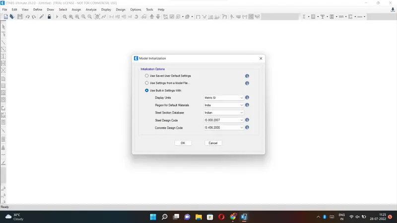
After setting the model Initialization the templates tab will open, select the Grid only and press ok.
Next, we need to do the settings in the Grid system data.
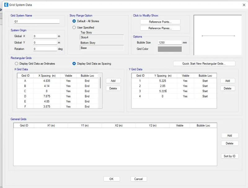
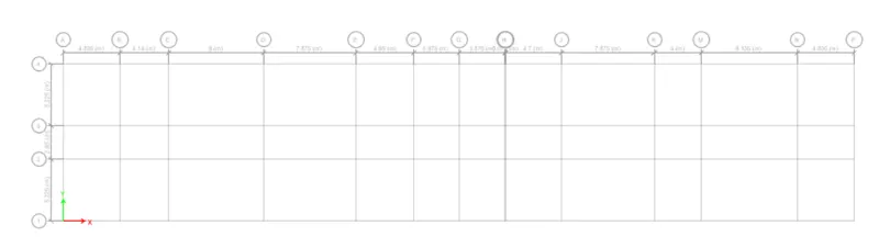
Next, we need to add the stories up to 3 stories in the Story Data.
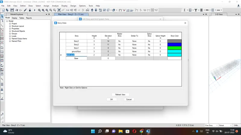
Next, the plan views and 3D Views are visible on the ETABS screen.
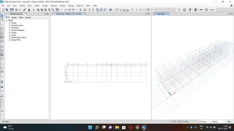
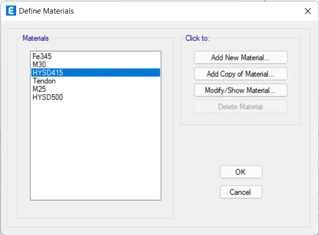
Next, we need to open define options and select material properties.
After selecting the material properties the new tab appears, then we add new materials by selecting the Add new material option.
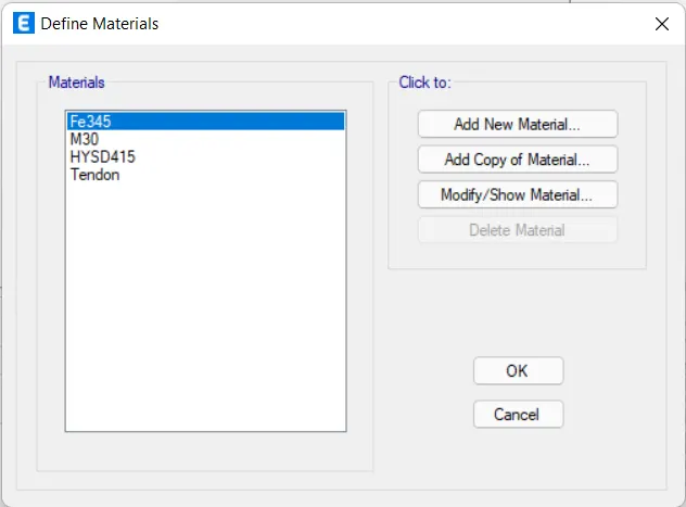
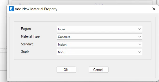
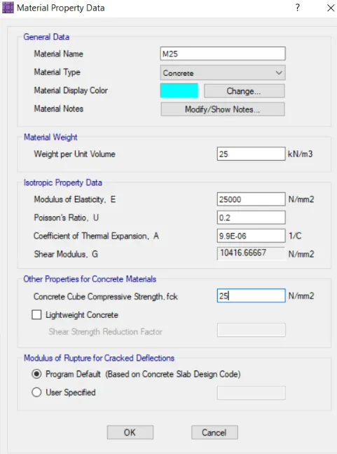
Now we need to add material type as concrete and grade as M25.
Next, we need to check the material property data.
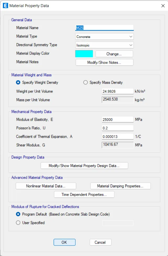
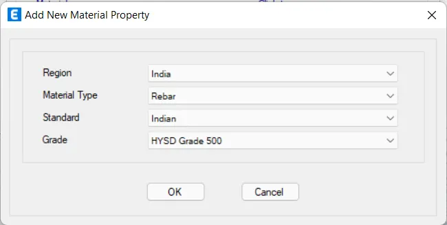
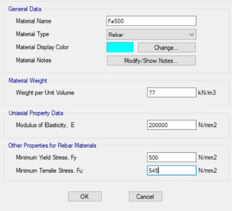
Now we need to add a new material type as rebar and grade as HYSD Grade 500.
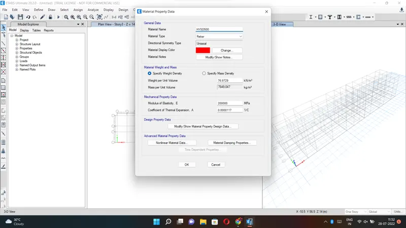
Next, we need to check the material property data.
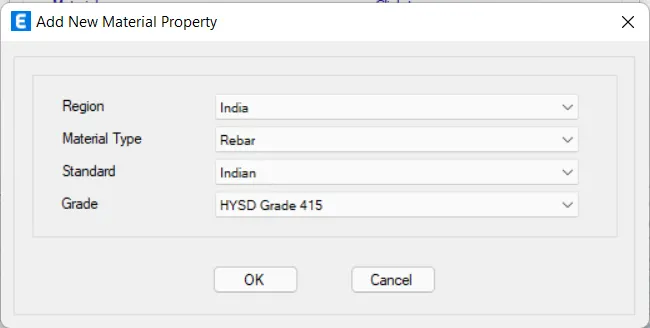
Now we need to add a new material type as rebar and grade as HYSD Grade 415.
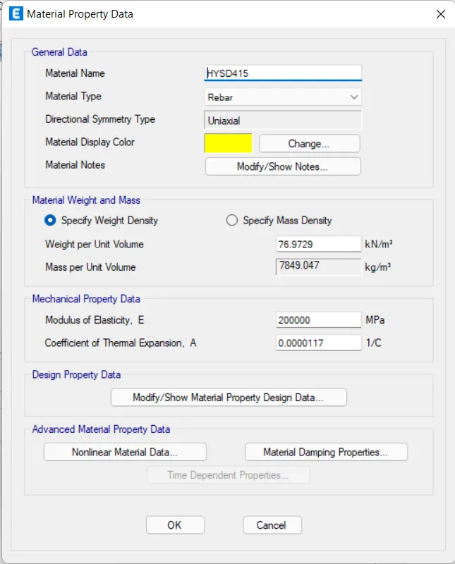
Next, we need to check the material property data.
Hence the materials are assigned
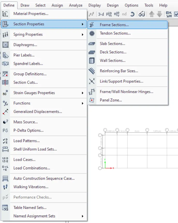
Now we need to select the section properties and click on the frame sections.
After selecting the frame sections the new tab will be visible, in that we need to select the Add New Property.
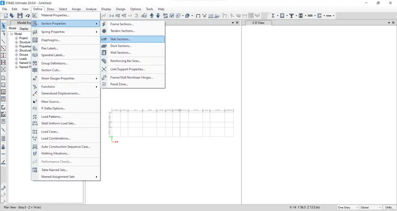
Next, we select the slab section option from the section properties.
Next, the slab properties tab will be visible, In that we select the Modify/Show Property option.
After selecting the Modify/Show Property option, the new tab appears.
In that, we need to put the slab name as Slab 125, which means slab with a thickness of 125mm.
And we take the concrete grade as M25.
Next, we have to click the ok option.
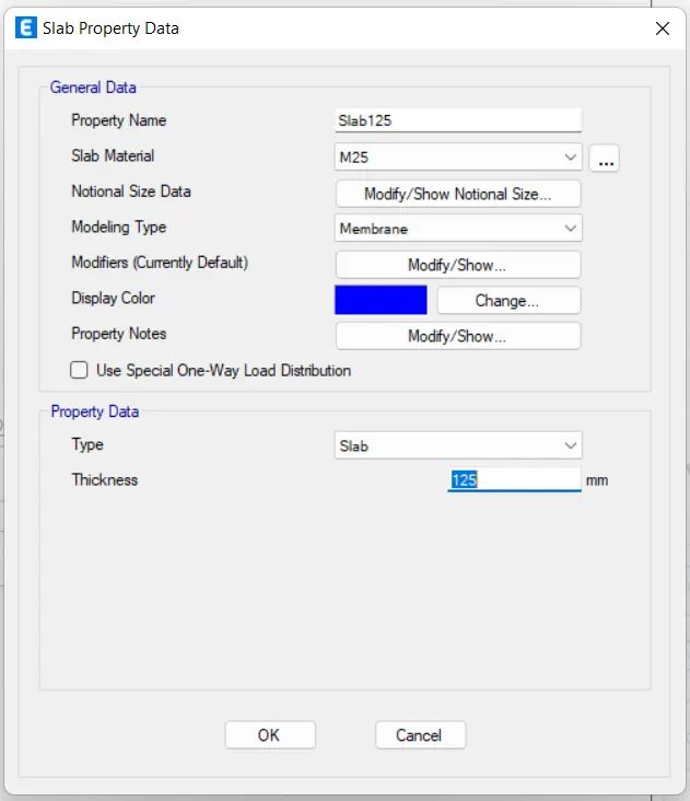
Now we take the slab thickness separately for the staircase with the thickness of 200mm.
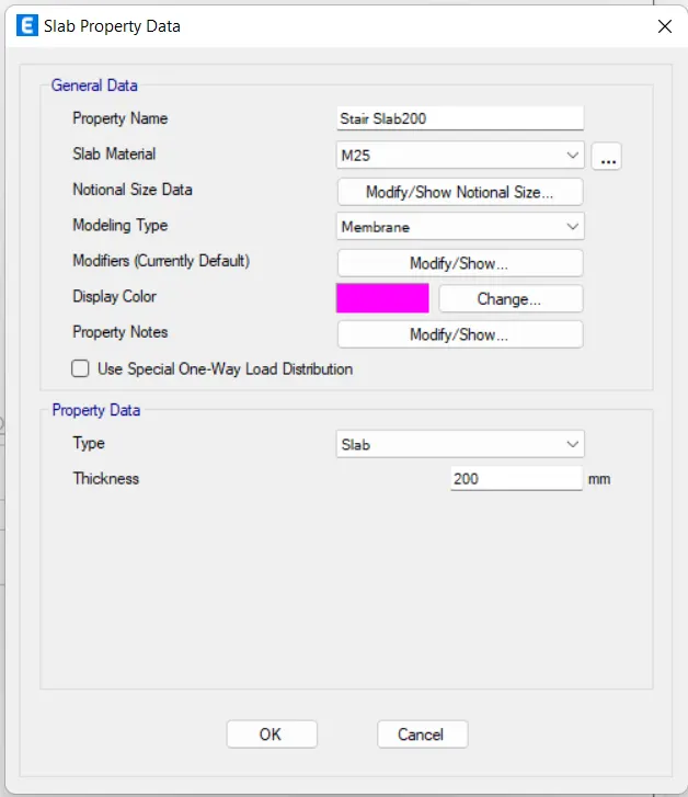
Hence the Slab properties are assigned
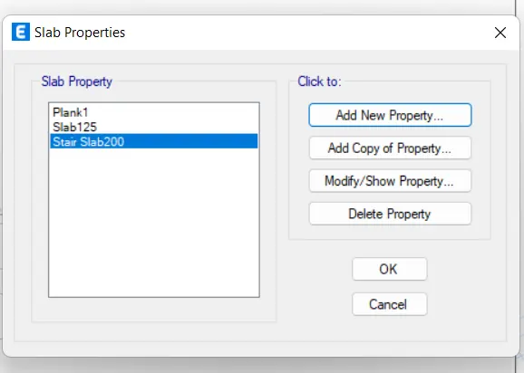
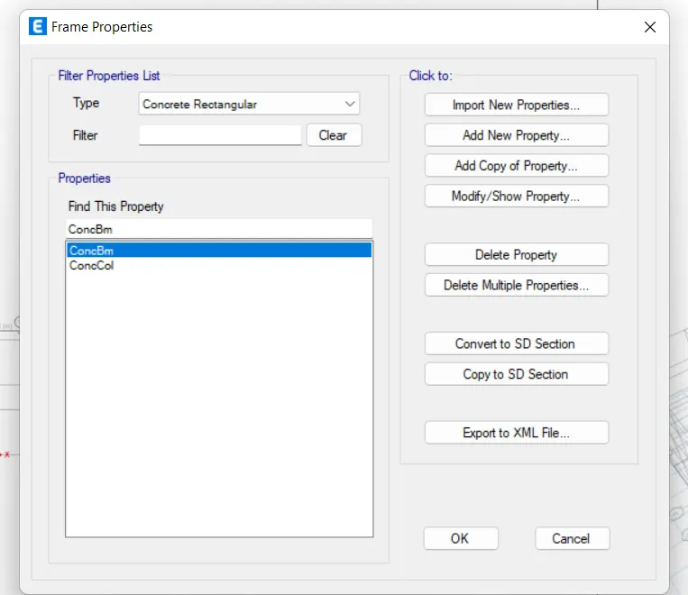
After selecting the Add New Property, the new tab appears.
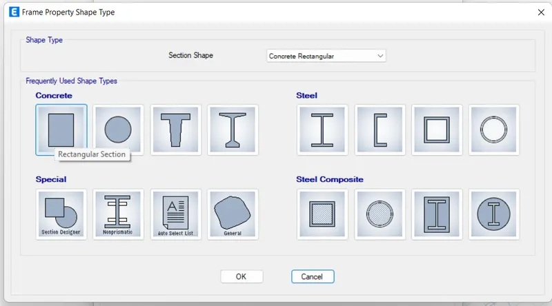
In that new tab, we select the Rectangular shape type in concrete.
Next, the frame section property data will be visible, In that, we add beam size as Beam 450 x 650.
Next, we need to select the Modify/Show Rebar option.
After selecting the Modify/Show Rebar option the new tab appears, In that we select the design type as M3 Design only (Beam).
Next, we select longitudinal bars with the grade of HYSD500.
Next, we select Confinement bars with the grade of HYSD415.
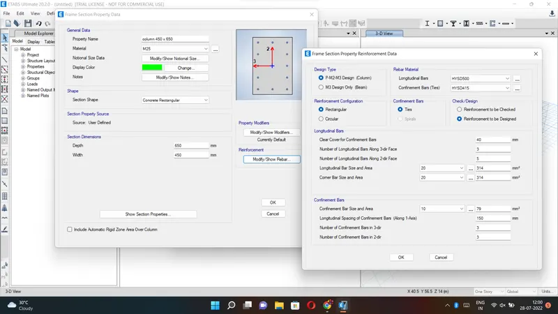
Next, we have to add the column size as column 450X650 in the frame section property data.
Next, we need to add the columns using the Quickdraw columns option.
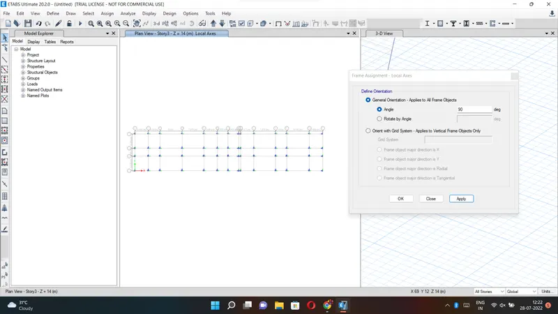
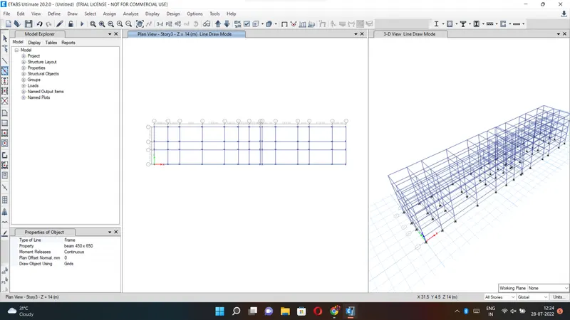
next, we need to add the beams using the Quickdraw beams option.
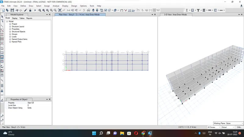
Next, we need to add the slabs using the Quickdraw floor/wall option.
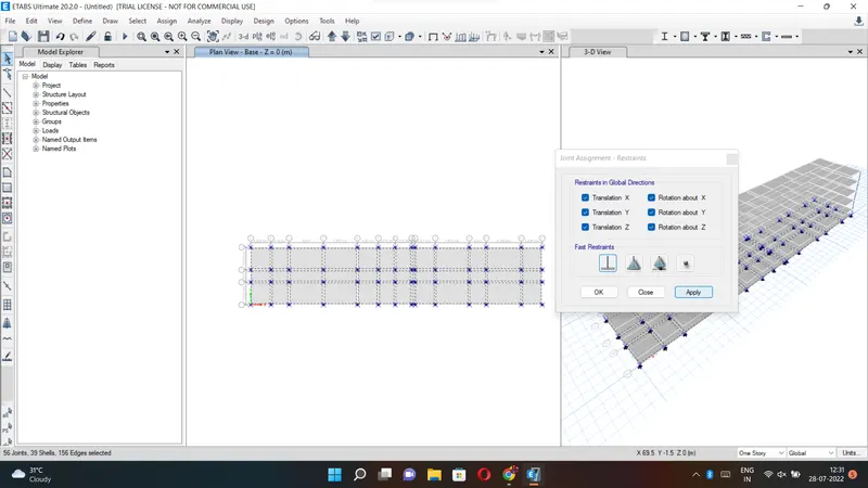
Now we go to the base plan and select all base joints.
Next, we select the Restraints from the joint option.
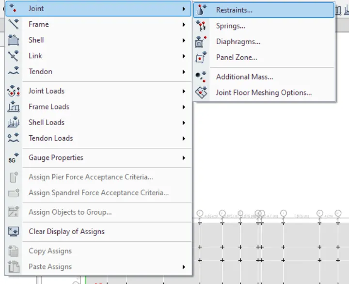
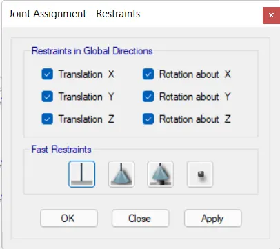
Now we need to select the fixed joint and click on apply and then click on the close button.
Next, we need to select the load patterns from the define option.
Now we should add Dead load, live load, Brickwall load, and earthquake load.
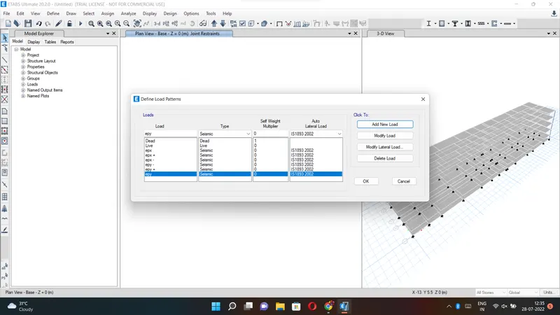
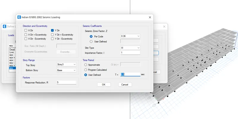
Next, we need to select EQX and click on the Modify Lateral Load, then the new tab appears.
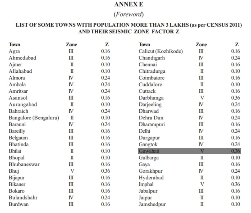
In this tab select X Dir and As per the IS 1893:2016, the seismic zone factor for Guwahati, Assam is taken as 0.36, as mentioned in the below table.
And we need to select site type as III.
Next click on the ok button.
Similarly, do this for all the seismic loads such as eqx,eqx+,eqx-,epy,epy-,epy+
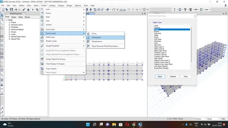
Next, we select the object type option.
After selecting the object type option, the new tab will be visible, In that select the beams and click on the select button, and close.
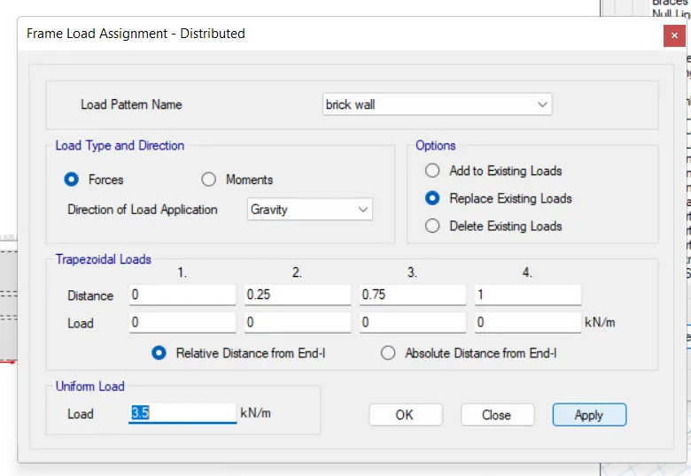
Next, we have to click on the assign option and then select frame loads, from the frame loads we select the Distributed option.
Then after the new tab will appear, we select the load pattern as Brick Wall and take the uniform load as 3.5 kN/m, and then click on the apply button and close.
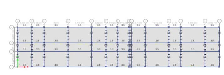
Now we select the object type option.
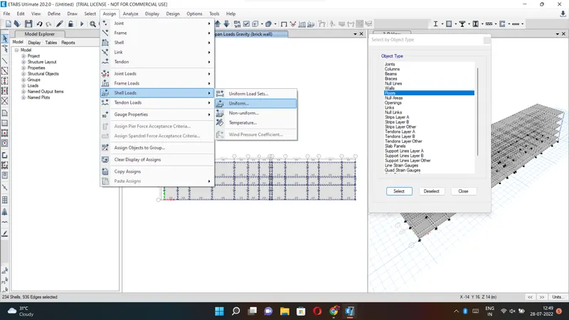
After selecting the object type option, the new tab will be visible, In that select the floors and click on the select button, and close.
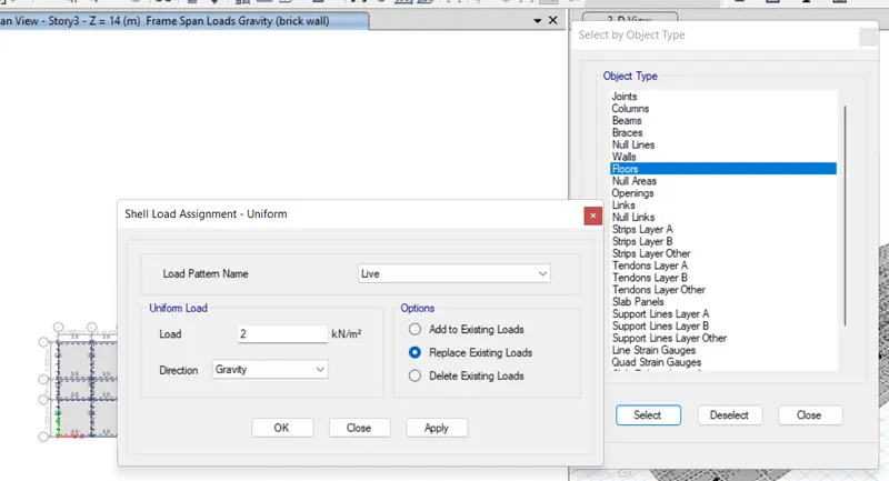
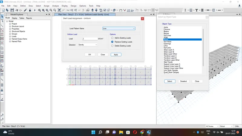
Next, we have to click on the assign option and then select shell loads, from the shell loads we select the Uniform option.
Here we need to consider the live load up to the 3rd floor with 2kN/m^2.
Next, from the define option, we select the mass source.
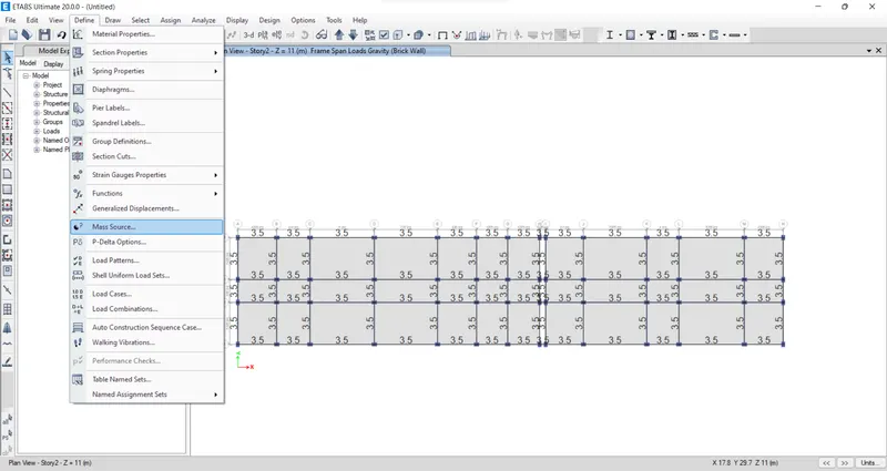
In the mass source tab, we select the Modify/Show Mass Source option.
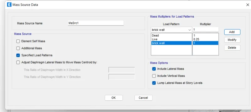
Next, we add the load patterns in the Mass Source Data.
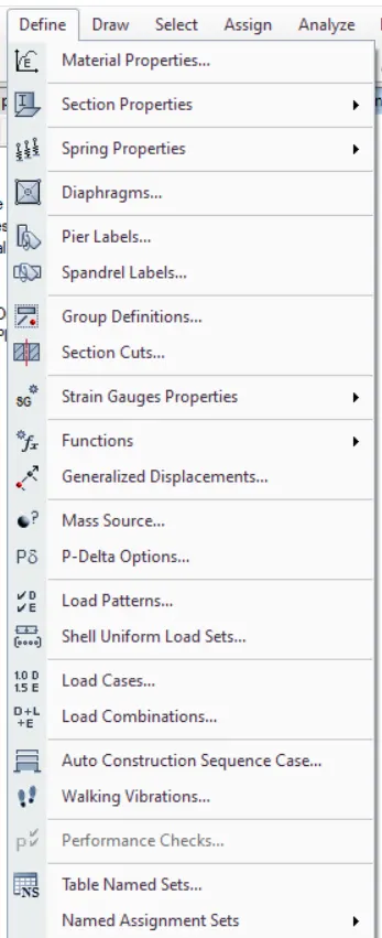
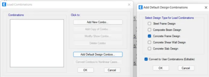
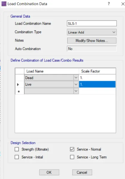
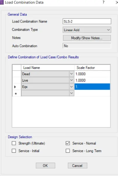
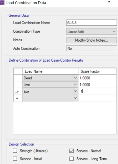
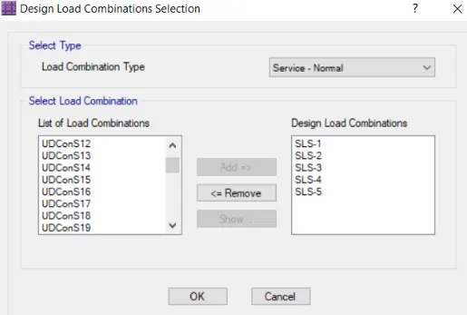
Next, from the define option, we select the load combinations.
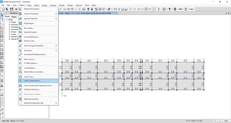
After selecting the load combinations the new tab is visible, In that, we select the 'Add Default Design Combos' option.
Next, we select concrete frame design in the Add Default Design Combinations.
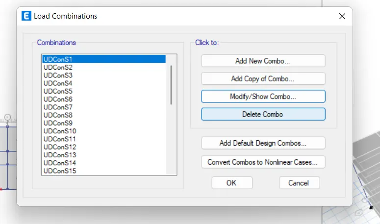
Now we can see here that the load combinations are visible.
From the 'select' option we select the 'object type' option.
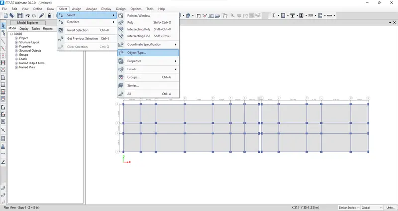
After selecting the object type option, the new tab will be visible, In that select the floors and click on the select button, and close.
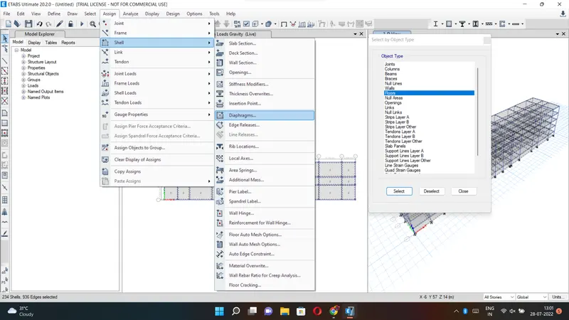
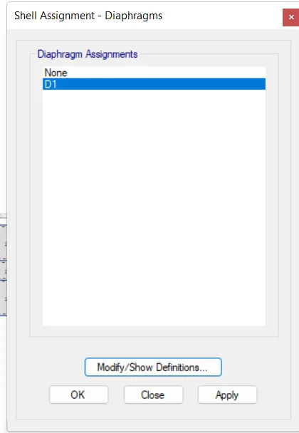
Next, we have to select the Diaphragms from the shell option.
After selecting the diaphragms the new tab will appear, in that select D1 and click on the apply button, and close.
Hence the diaphragms are assigned.
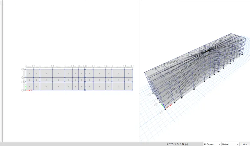
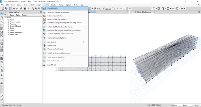
Next, we have to check the model by clicking the check model option.
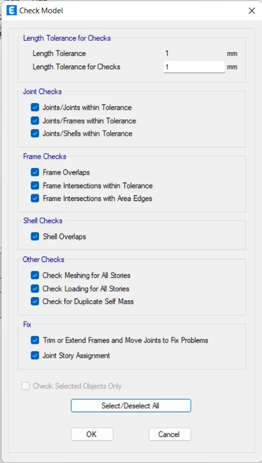
Next, the check model tab will appear, In that select all options and click on the ok button.
After the model is checked, then the warning tab will be visible and it tells that there are no warning messages.
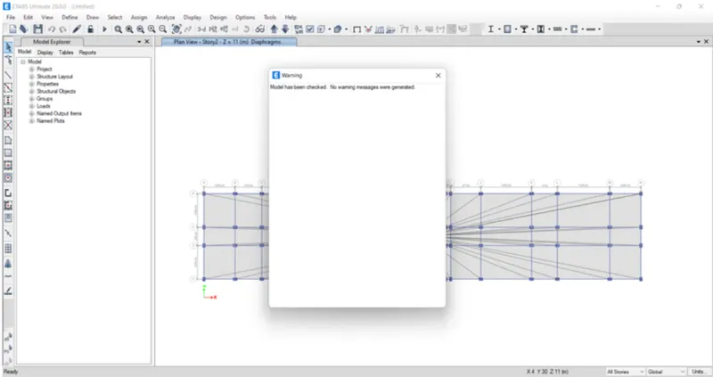
Now we have to do the run analysis.
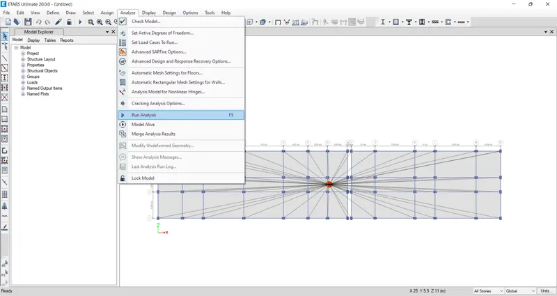
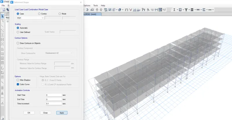
After Run Analysis we select the 'show deformed shape' option, then the new tab appears.
In the deformed shape tab, we select Earthquake load in the load case.
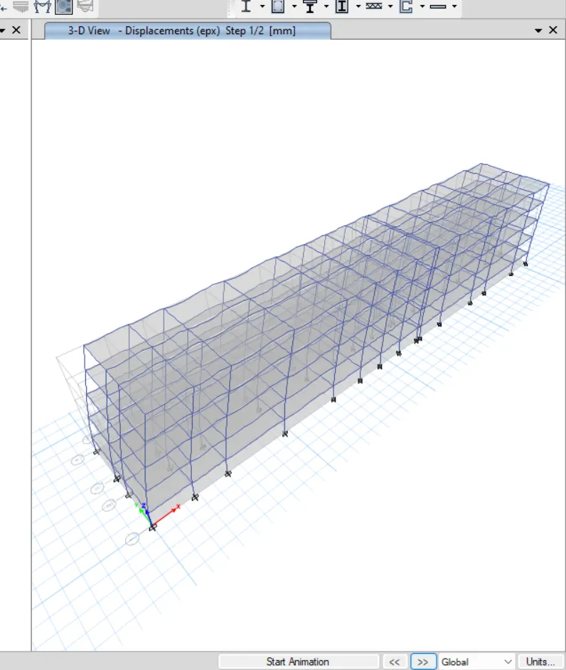
Next, we see the deformed shape of the structure with the Earthquake loads.
Similarly, we have to do this for all the remaining loads.
Next, we have to start the Beam design and Column design by selecting the 'Start Design/Check' option.
After completion of the beam design and column design, we need to select the 'Display Design Info' option.
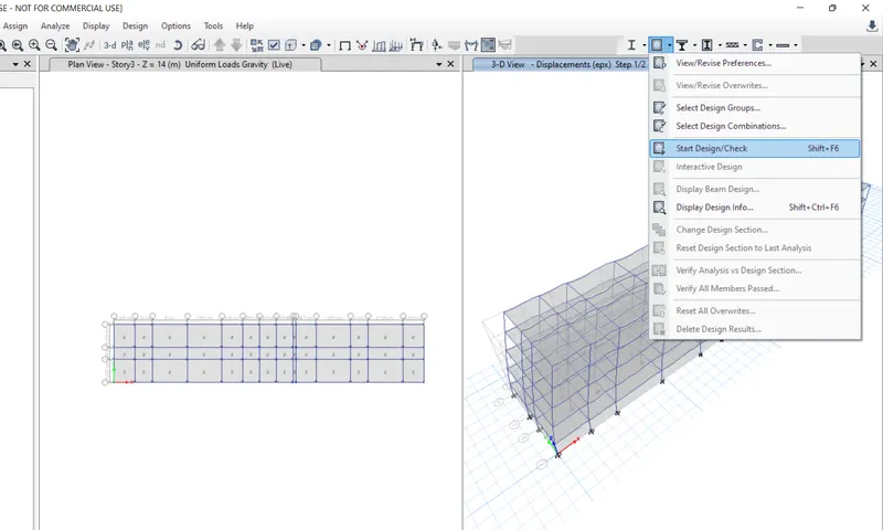
After selecting the 'Display Design Info' option the new tab appears, In that we select the Longitudinal Reinforcing in the Design Output and click on the OK button.
Next, the longitudinal reinforcement details will appear.
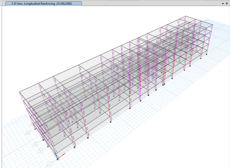
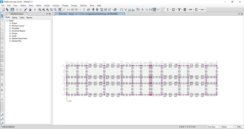
Next, we draw the Reinforcement diagram of a 7 span continuous beam along Grid-1, and also need to provide the reinforcement details.
The maximum Ast for the bottom support is 637mm^2 and the bottom middle is 637 mm^2
The maximum Ast for the top support is 1038mm^2 and the top middle is 637 mm^2
Now we provide 6-12dia. at the top and bottom.
Next, we provide 3-16dia. at the top supports the continuous beam.
Now, here we can see the details of column reinforcement.
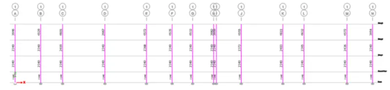
Here we take column-1L for reinforcement, now take the column size as 650mm X 450mm.
The maximum Ast for the column-1L is 4632mm^2
Now we provide 16 bars with 16mm dia.
And we provide the size of the stirrup as 10mm, for Zone A we provide 100mm spacing, and for Zone C we provide 150mm spacing.
And the details of shear reinforcement are provided as per the special confining reinforcement provision of clause 8.1 of IS 13920 - 2016.
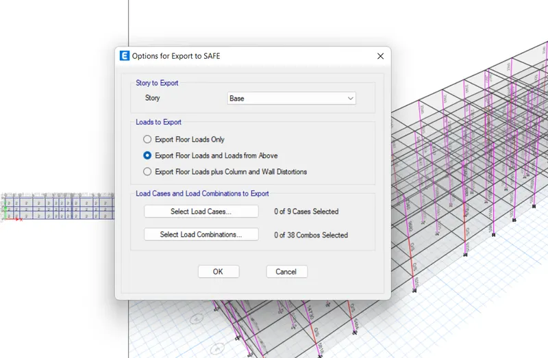
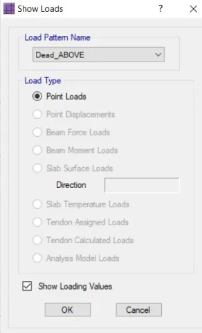
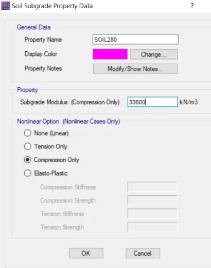
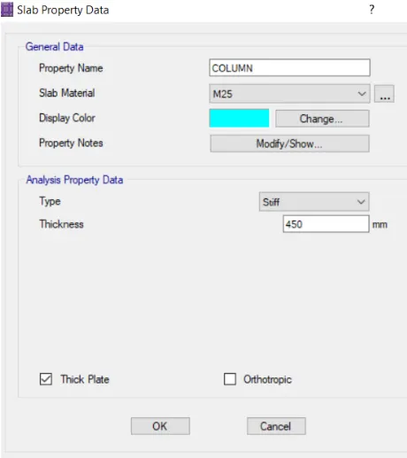
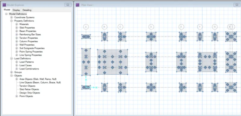
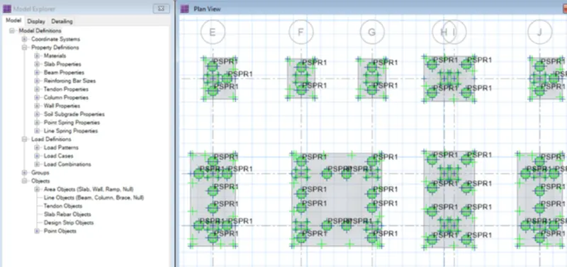
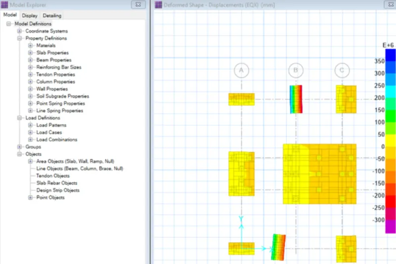
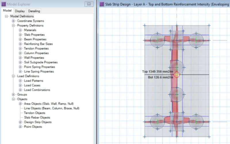
Next, we have to export the base floor loads and loads from above to the SAFE 2016.
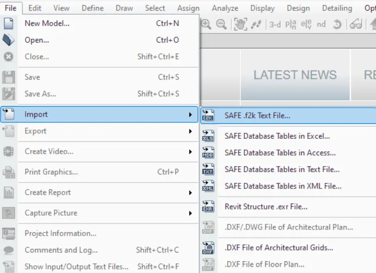
Next, we open the SAFE 2016 and import the file.
RESULT:
The structural model of the G+3 building has been Designed & Analyzed in ETABS & the Foundation is designed and analyzed in SAFE 2016. Necessary checks have been carried out and also verified the values with the code.
The results of each drawing drawn in ETABS, SAFE, and AutoCAD are attached.