Project 2_Design & Analysis of a Hostel building at Guwahati, Assam
PROJECT 2
Design & Analysis of a Hostel building at Guwahati, Assam
> Synopsis/Overview:
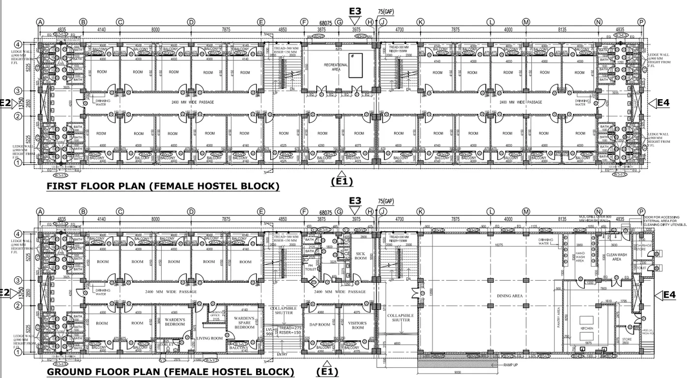
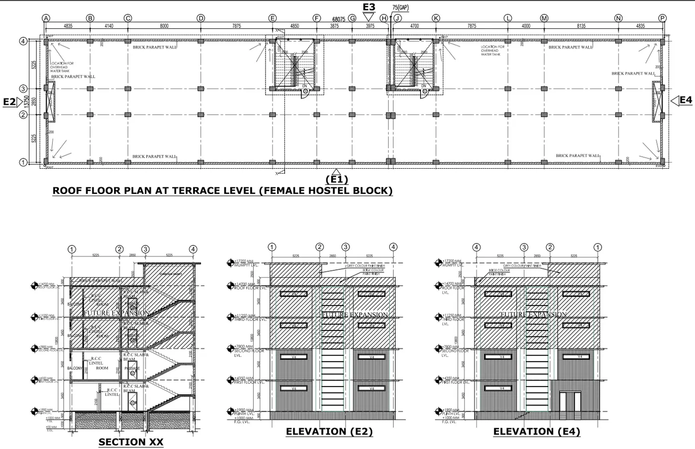
In this project, participants will get to experience the entire design process from modelling, analysis, design and preparation of construction drawings. The architectural drawings of a G+3 RCC building is provided.
* The following information on the building is to be used:
· * Location – Guwahati, Assam
· * Function – Hostel block in an academic institute
* The walls will be made of AAC blocks. Other loadings are to be calculated as per the architectural drawings.
* The buildings rests on type 3 soil. Piles of length 10 meters and 500 mm diameter with load carrying capacity of 280 KN is to be used.
* The ground floor level will be at a height of 2 meters above existing site level to avoid flood water enter the building.
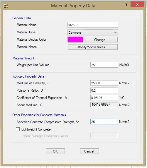
* M25 grade of concrete with Fe500 for longitudinal reinforcement and Fe 415 for shear reinforcement is to be used.
* The following design IS codes will be required for reference:
1. IS 875 Part 1
2. IS 875 Part 2
3. IS 13920
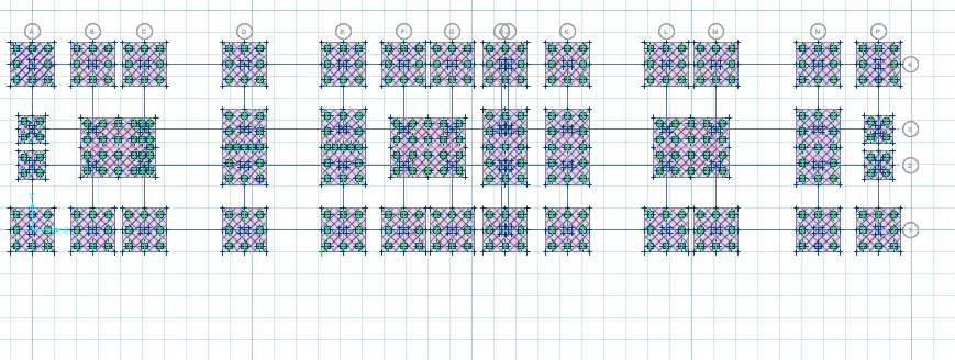
4. IS 1893
5. IS 2911 Part 2
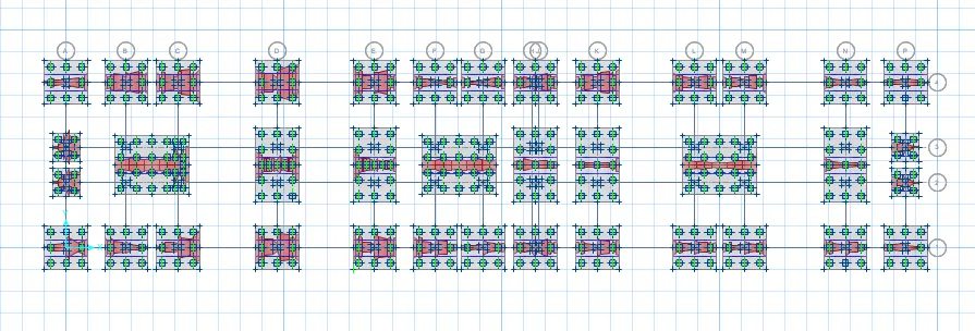
6. IS 456
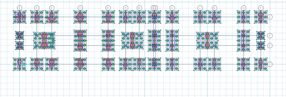
7. SP 34
> Objective:
The goal is to model, analyze, design, and create construction drawings for a G+3 reinforced concrete building located in Guwahati, Assam.
> Introduction:
ETABS is specialized engineering software designed for the analysis and design of multi-story buildings. SAFE, on the other hand, utilizes advanced three-dimensional finite element technologies for structural engineering. In this project, we will use ETABS for the analysis and design of the G+3 building, followed by SAFE for the foundation design.
> Procedure:
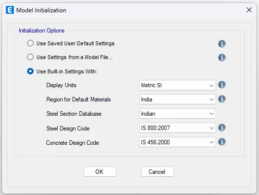
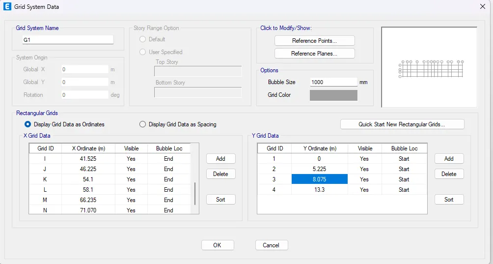
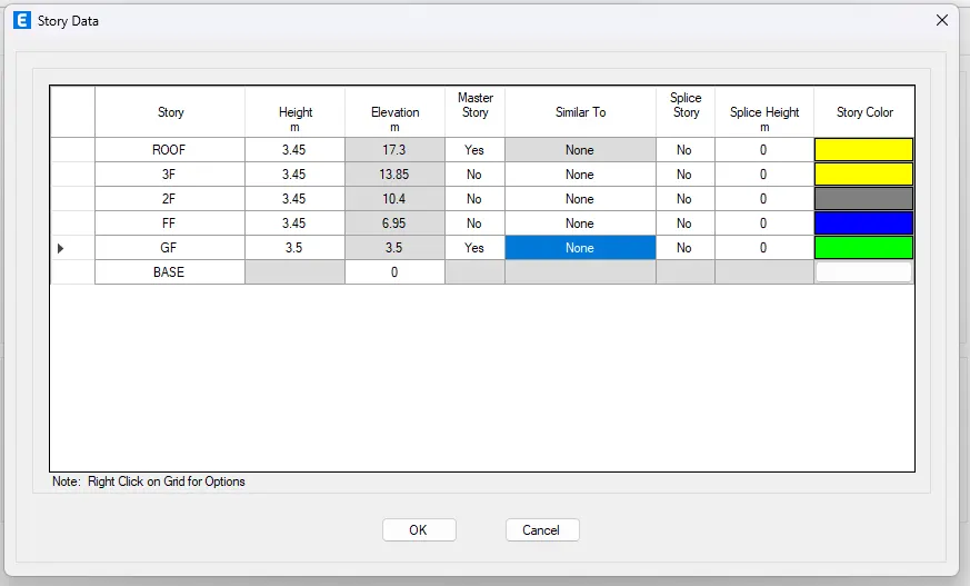
I. To begin, open the ETABS software and input the grid and story information.
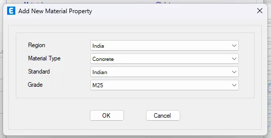
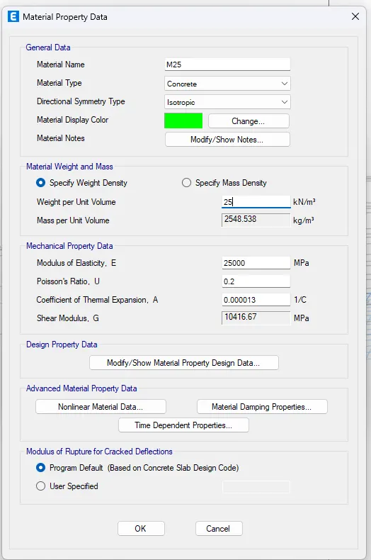
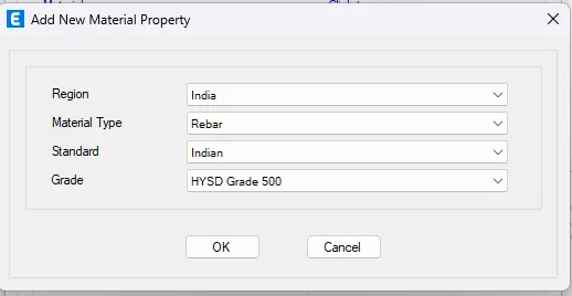
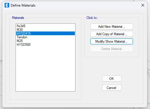
II. Next, we have to specify the material properties, including concrete with a grade of M25, and reinforcement bars with grades Fe415 and Fe500
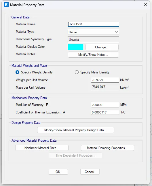
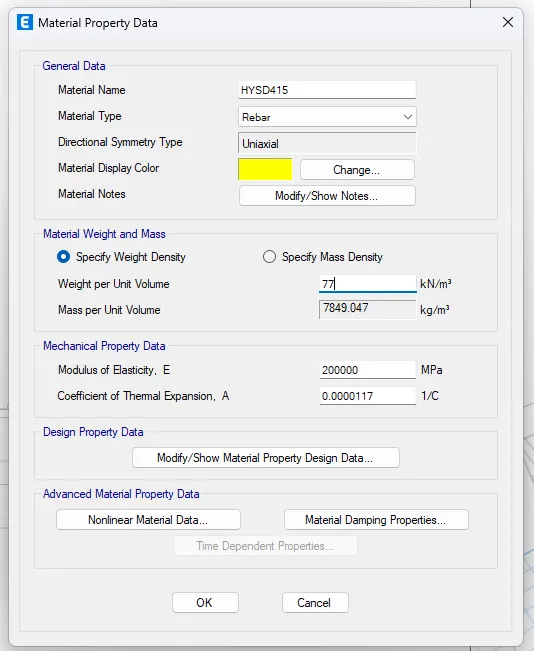
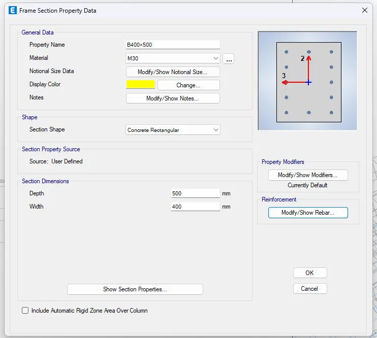
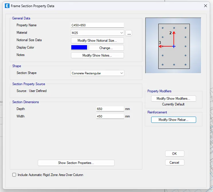
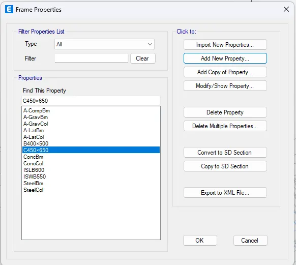
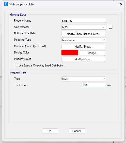
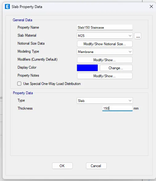
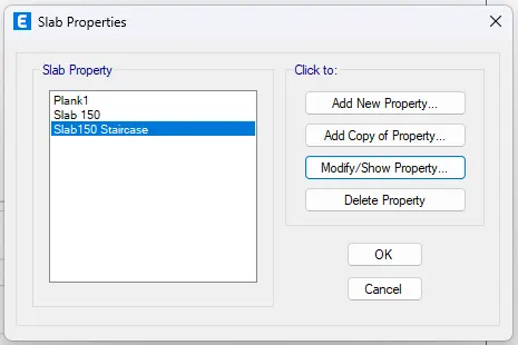
III. Next, specify the section properties, such as the dimensions of beams (400x500), columns (450x650), and the thickness of slabs (150mm). Additionally, define the section properties for slabs, including a separate one-way slab for the staircase.
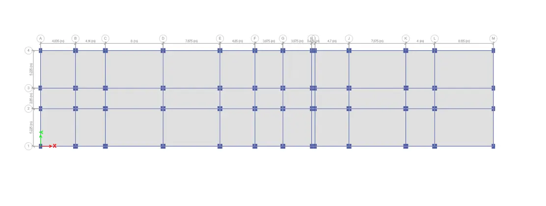
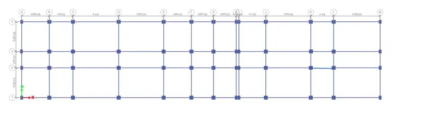
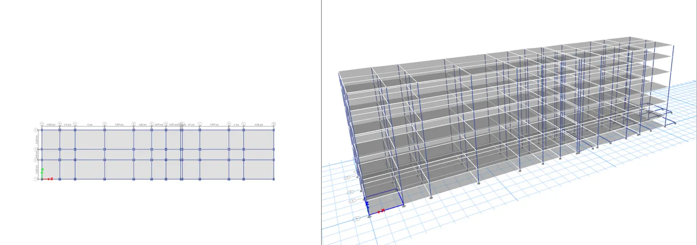
IV. After establishing the material properties, the next step is to position the components. Initially, place the frame elements, followed by the placement of slab elements.
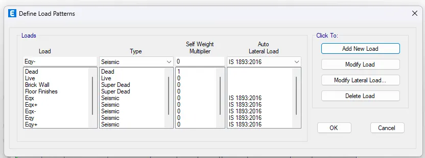
V. After positioning the elements, the next step is to specify the load cases. Define the load cases, including Dead Load (DL), Live Load (LL), Earthquake in the X direction (Eqx), Positive X-direction Earthquake (Eqx+), Negative X-direction Earthquake (Eqx-), Earthquake in the Y direction (Eqy), Positive Y-direction Earthquake (Eqy+), and Negative Y-direction Earthquake (Eqy-).
VI. Now, it's time to apply these loads.
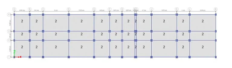
* For the live load, use a value of 2kN/m2 according to IS875:part 2.
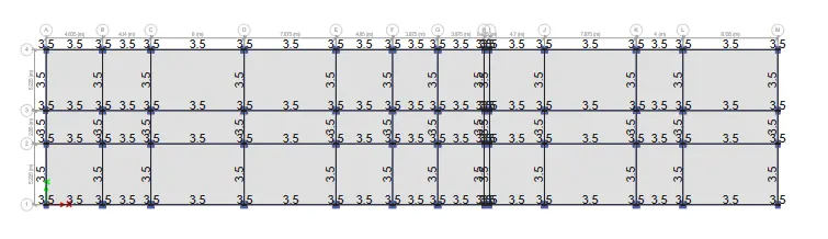
* Assign Brickwall load arround 3.5kN/m.
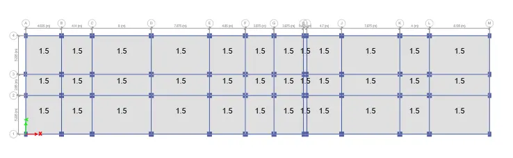
* Apply a load of 1.5kN/m2 for floor finishes.
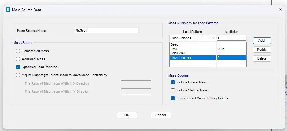
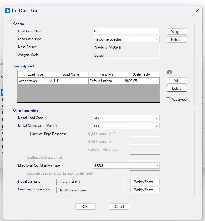
VII. Subsequently, assign the joints. Additionally, define the mass source and describe the response spectrum function.
VIII. Afterwards, establish the load combinations.

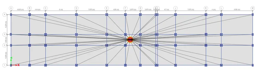
IX. Following that, assign a diaphragm to the shell.
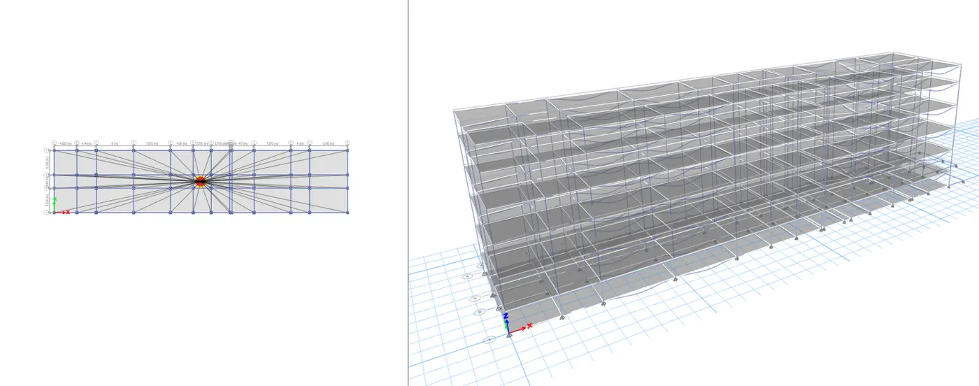
X. Following that, we can proceed with the analysis and design.
XI. Following that, it is necessary to examine the story drift for RSx and RSy to ensure it falls within the specified limits according to IS1893.
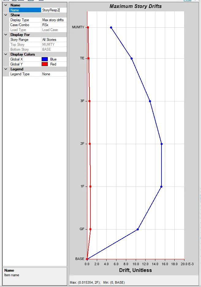
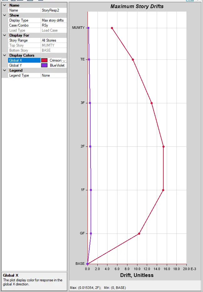
XII. Therefore, both story drifts comply with the code limits.
XIII. Next, proceed to conduct the concrete frame design and extract the design results for beams and columns, including both flexural and shear reinforcement.
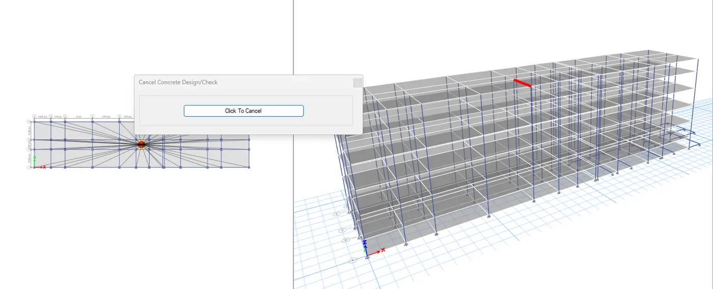
> Reinforcement along the length of the beam.
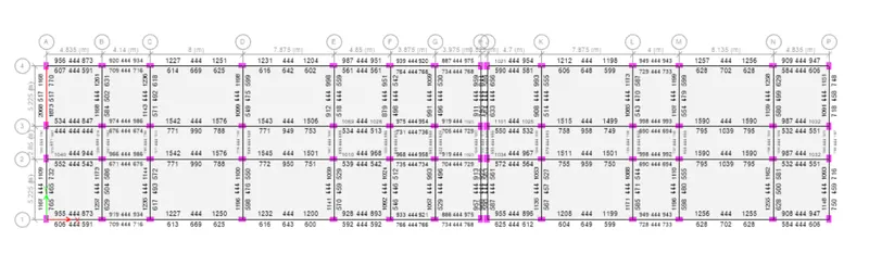
> Shear reinforcement in beams.
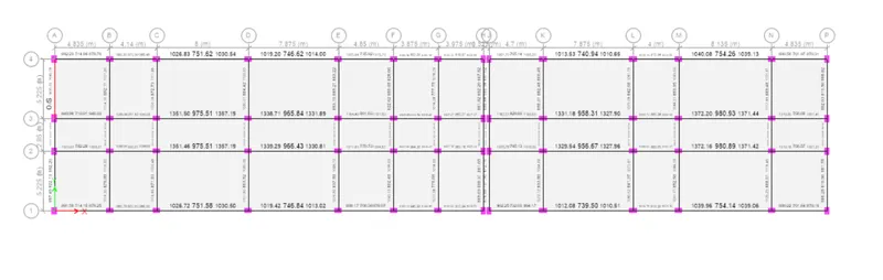
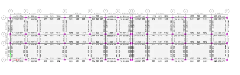
XIV. The design results indicate that three beams are experiencing shear failure. To enhance safety, it is necessary to modify the beam sizes. The size of two beams has been adjusted to 450x650mm, while the size of the remaining beams is retained at 450x750mm.
> Reinforcement along the length of the beam.
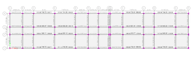
> Shear reinforcement in beams.
> Reinforcement along the length of the column.
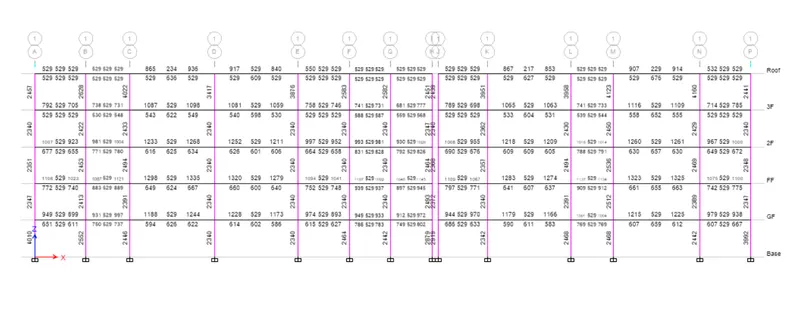
> Shear Reinforcement in columns.
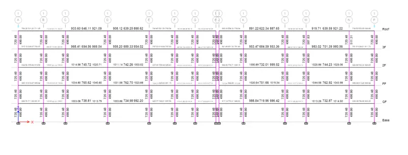
PART-2
1. Therefore, the design process is finished. Next, export the base reactions and load conditions in f2k format for footing design using the SAFE software.
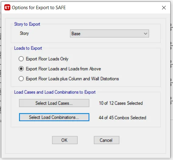
2. Now, import the SAFE f2k file into the SAFE software. Consequently, all the reactions and loads have been successfully imported into the software.
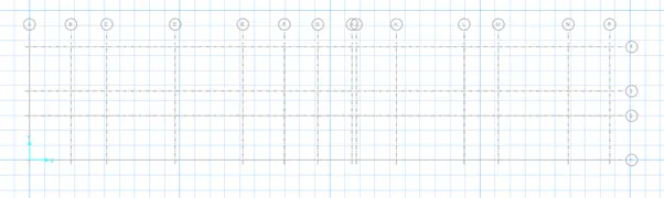
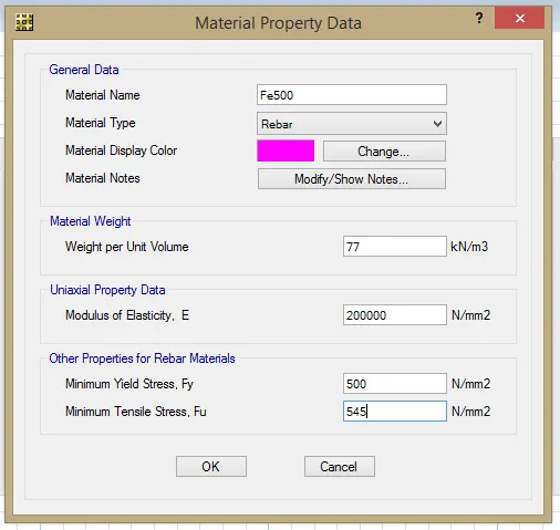
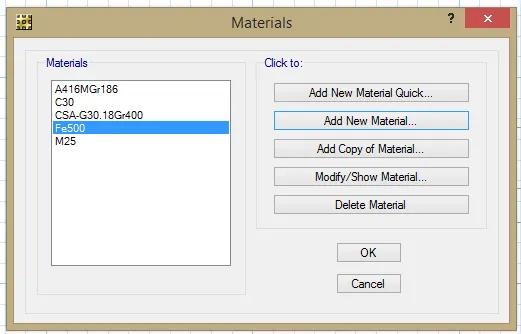
3. DEFINE the materials for both concrete and rebars.
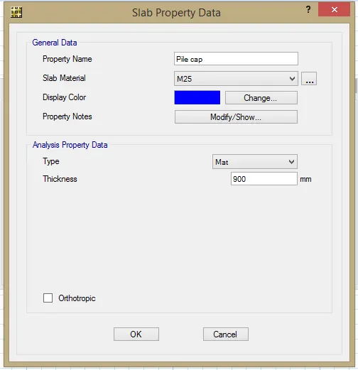
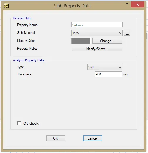
4. Define slab properties
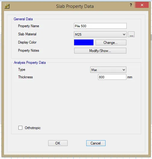
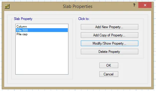
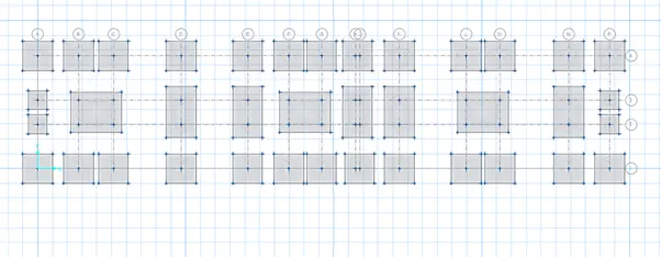
5. Afterward, utilize the "draw point" option to place points for the footings corresponding to each column.
6. Now, navigate to the "draw" option and create points on the footing to indicate the locations where piles are to be developed.
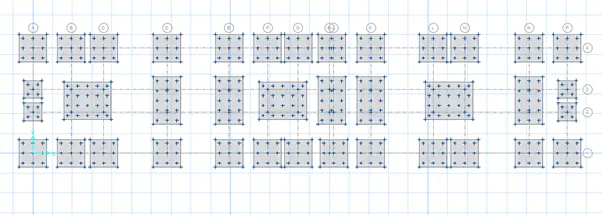
7. Next, proceed to input piles using the previously mentioned option and specify the material property as "pile500."
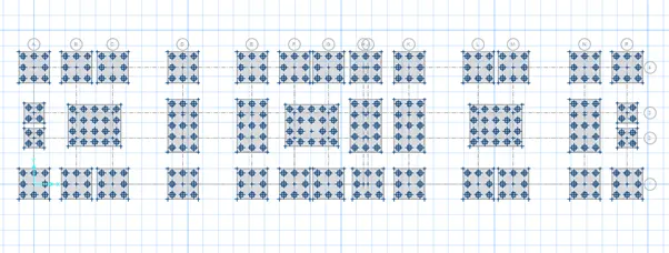
8. Subsequently, position the columns at the intersections of the grid.
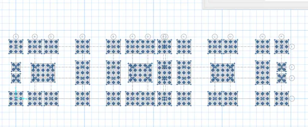
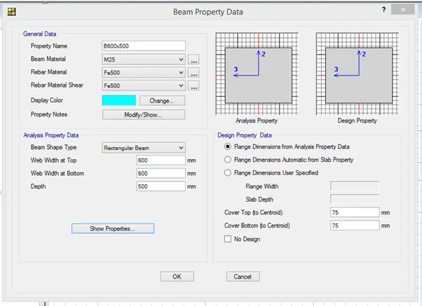
9. Define beam for tie beams
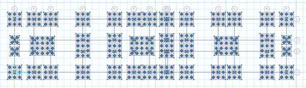
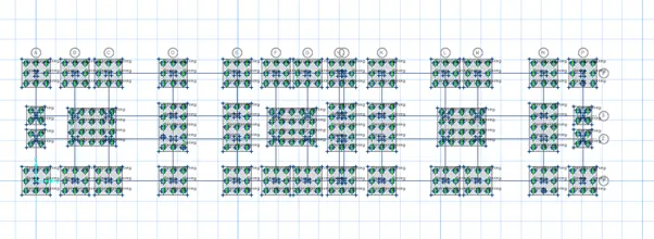
10. Now, it is necessary to assign springs at the locations where the piles are situated. To accomplish this, calculate the spring constant.
> Spring Constant: AE/L =196346.5×25000/10000 = 490873 N/mm
> Assign the spring constant
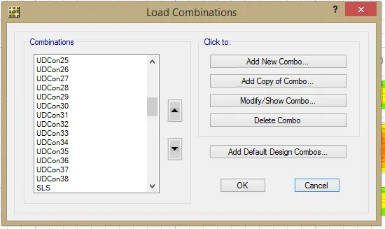
11. Now, establish the load combination for both serviceability limit and ultimate limit.
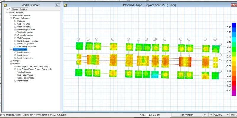
12. Next, it's necessary to review the design results.
13. The displacement values are within the acceptable limits, indicating that the structure is safe.
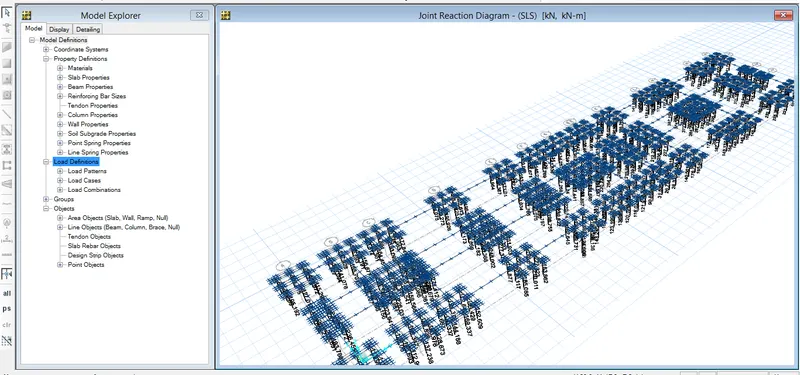
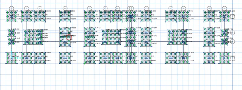
14. Check the reaction:
15. Punching shear values also fall within the acceptable range.
16. Now, it's time to design the strip.
17. Now, proceed with the design once again.
18. For strip layer A.
19. For strip layer B
> Result/Outcome:
* The modeling, analysis, and design of the G+3 building have been successfully completed using ETABS software.
* Additionally, the foundation design, including the pile cap and piles, has been carried out using SAFE software.