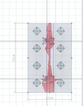
Project 2_Design & Analysis of a Hostel building at Guwahati, Assam
AIM : To carryout modelling,analysis,design and preparation of construction drawings of a G+3 RCC building situated in Guwahati Assam.
PROCEDURE :
STEP 1 :
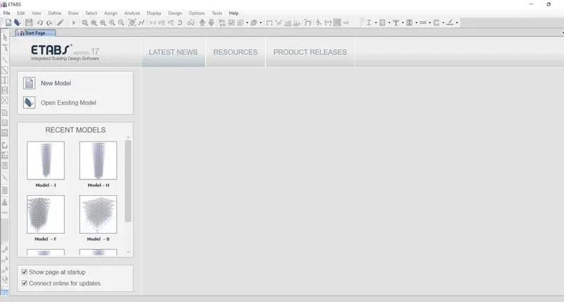
- Open the ETABS software from desktop icon.
- Once software is open - click on New model.
STEP 2 : - A model initialization setting will open.
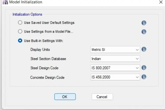
- Select - Metric SI units
- Select section database - Indian
- Seleact steel code - IS800:2007
- Select concrete design code - IS456:2000 and click OK
STEP 3 : - In new model Quick templates under grid dimensions select the custom grid spacing.

- Click on display grid data as spacing
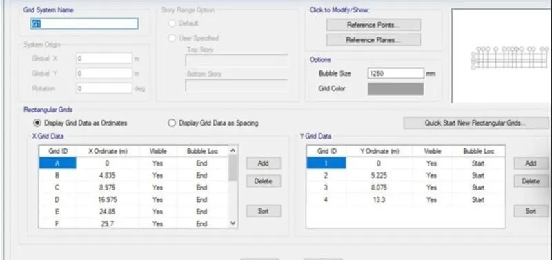
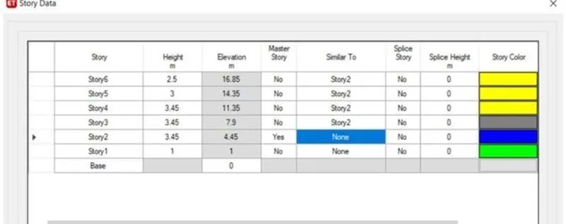
- Now input the storey details
- As given in question and story 1 was selected as the Master story and click on OK
STEP 4 : - A plan and 3D view of model is created in model space.
STEP 5 : - Now click on Define
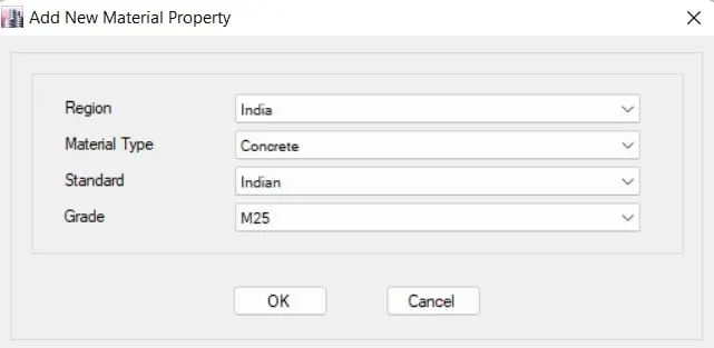
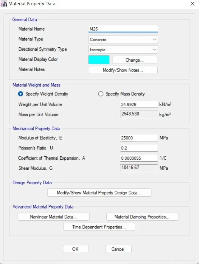
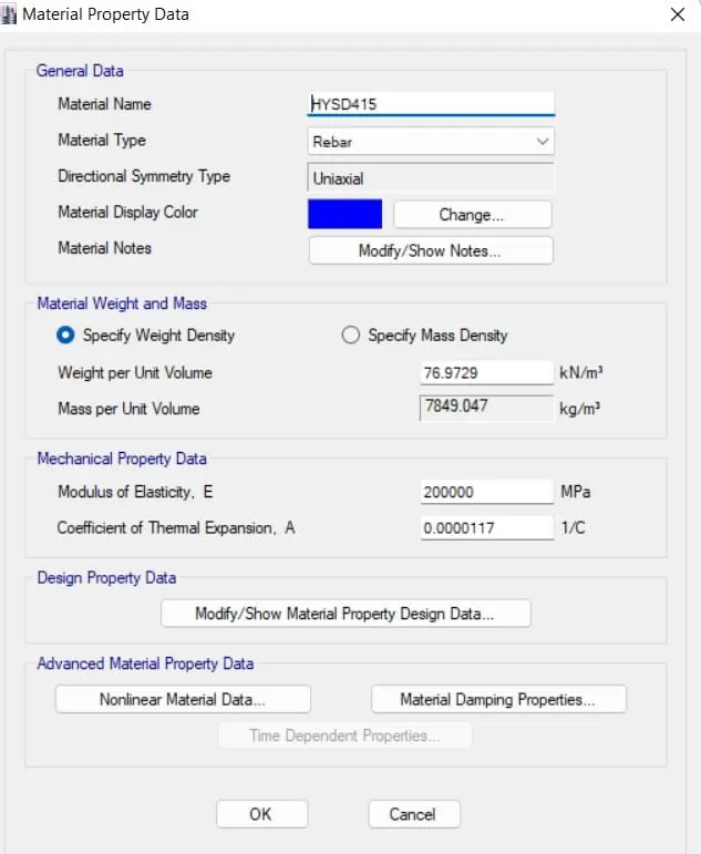
- Click on material properties
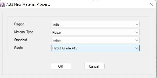
- Define properties for concrete and steel
STEP 6 : - Now we have to define section properties ( column and beam )
- Click on Define
- Select - section properties
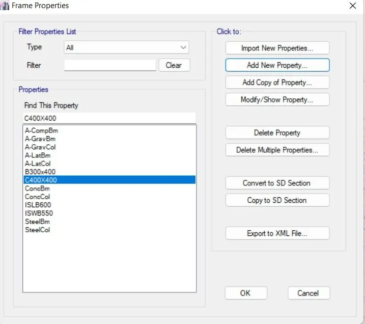
- Click on frame section
- Click on add new property
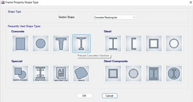
- select rectangular shape
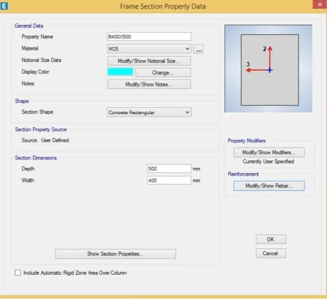
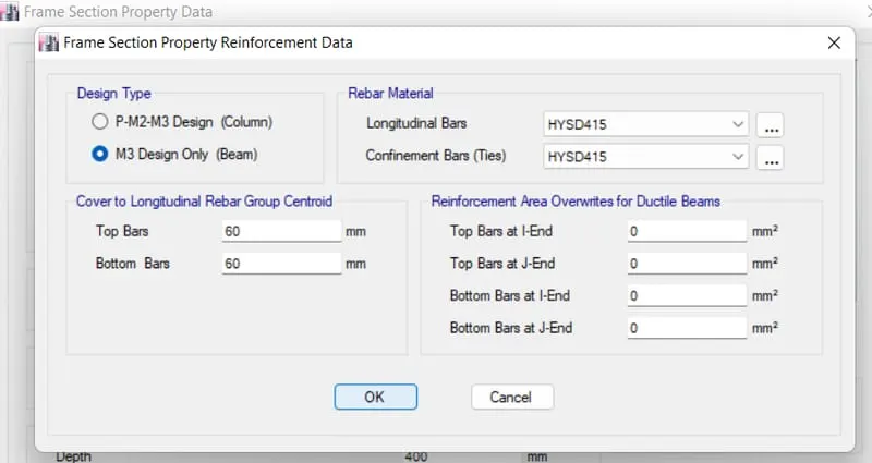
- Give property name Beam - 400 x 500 (given) and then put all the values as shown in table.
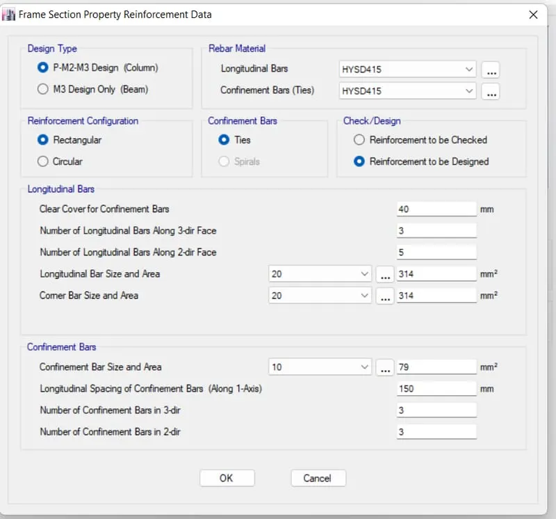
- Click on modify / show rebar and put the values as shown in table.
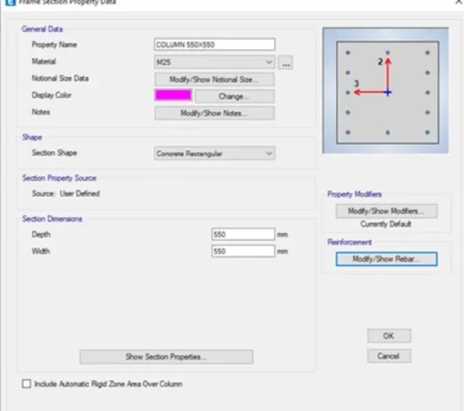
- Similarly same steps for column also.Add column size - 550 x 550mm
STEP 7 : - Now we have to define slab
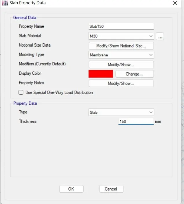
- Click on Define > slab properties > slab section
- Add thickness 150mm
STEP 8 : - Now we have to keep the 3D view also to see the properties.
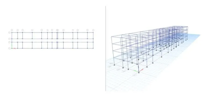
- Now we have to add the columns and beams
- Click on Quick Draw column option
- Select the column properties which we have defined earlier
- Draw columns at grids as shown in below
- Note that - all stories option should be selected which is at the bottom.
- Similarly we have to draw beams also.
STEP 9 : - Now we have to add slabs
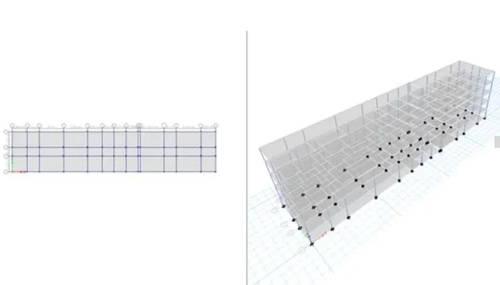
- Select Quick draw floor
- Draw the slabs as shown below.
STEP 10 : - Now we have to assign loads
- Define > load patterns
- Define load pattern dialogue box will open
- Add the following loads and select the IS code for Seismic code as IS-1893
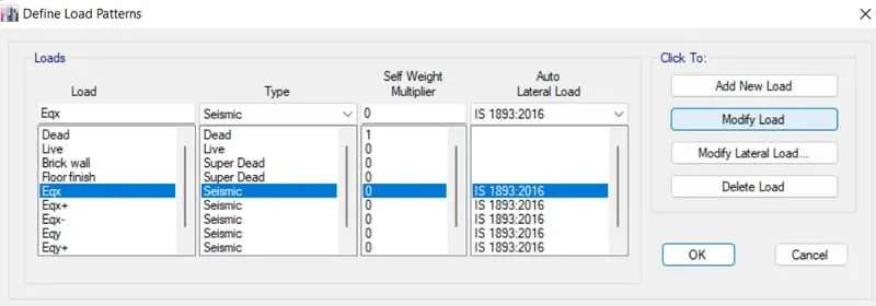
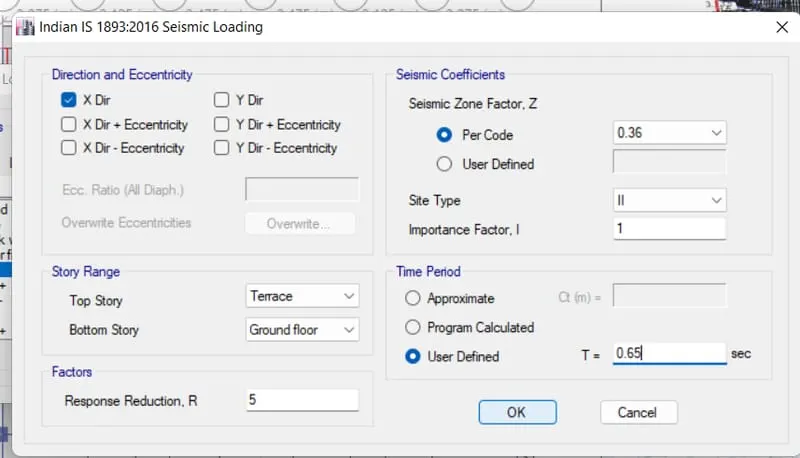
- The direction and eccentricity were selected as the X-direction
- The response reduction factor R was taken as 5
- Put all values as shown in following table
STEP 11 : - Now we have to assign the loads to the structure
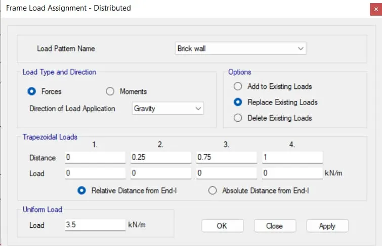
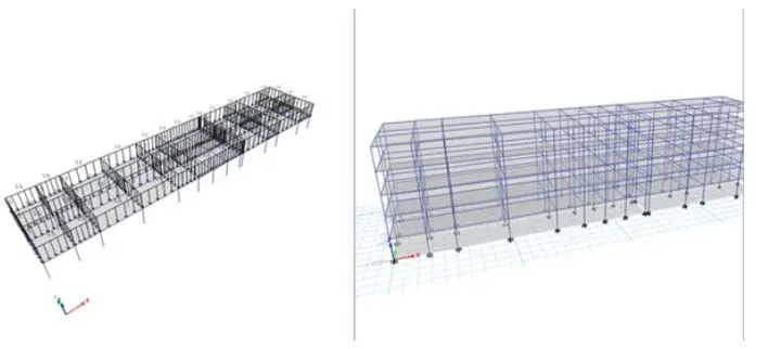
- AAC block load - 3.5 KN/m2
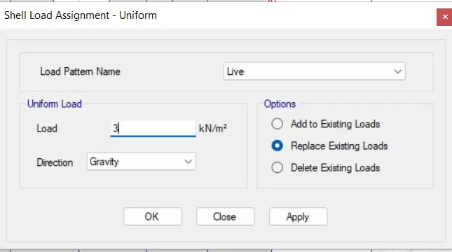
- Live loads were applied to slabs next.
- As per IS 875 in residential buildings its 2KN/m2 for rooms
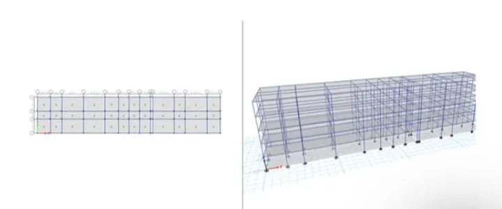
FLOOR FINISH - In the same way select slabs to assign floor finish which is 1KN/m2
STEP 12 : - Now we have to assign Mass source
- For that Define menu - mass source options to open the mass source dialogue box
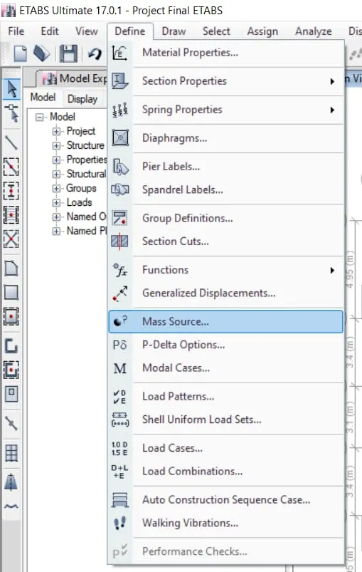
- Now select Modify mass source data option and click OK.
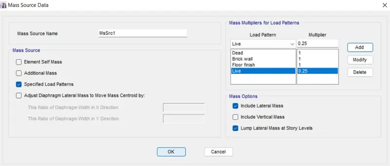
- Now mass source data was provided as shown and load pattern was also added to it.
- For live load upto 3KN/m2 - we have to assume some fraction at live load i.e.25%
STEP 13 : - Now we have to assign diaphragm
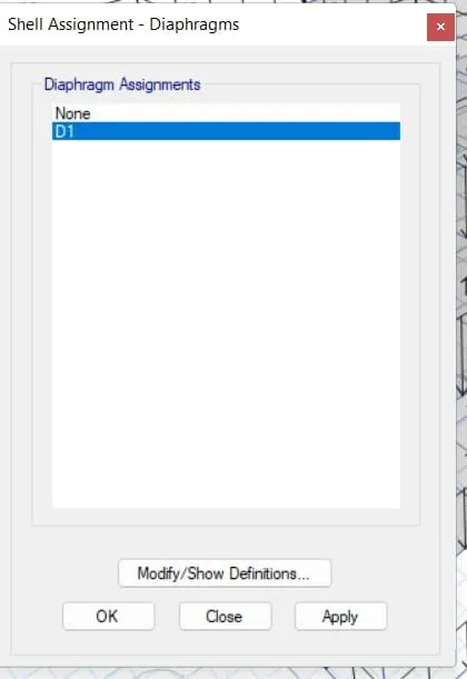
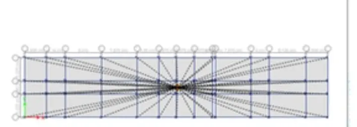
- Assign > shell > diaphragm then one dialogue box will open
- Select D1 from diaphragm assignments and click OK.
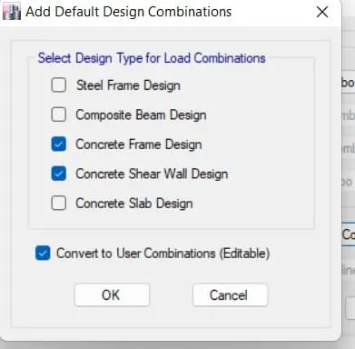
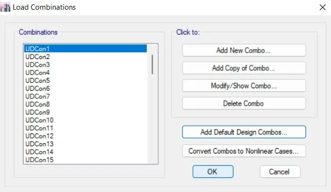
STEP 14 : - Now we have to add the load combinations
- Click on Add default Design combo
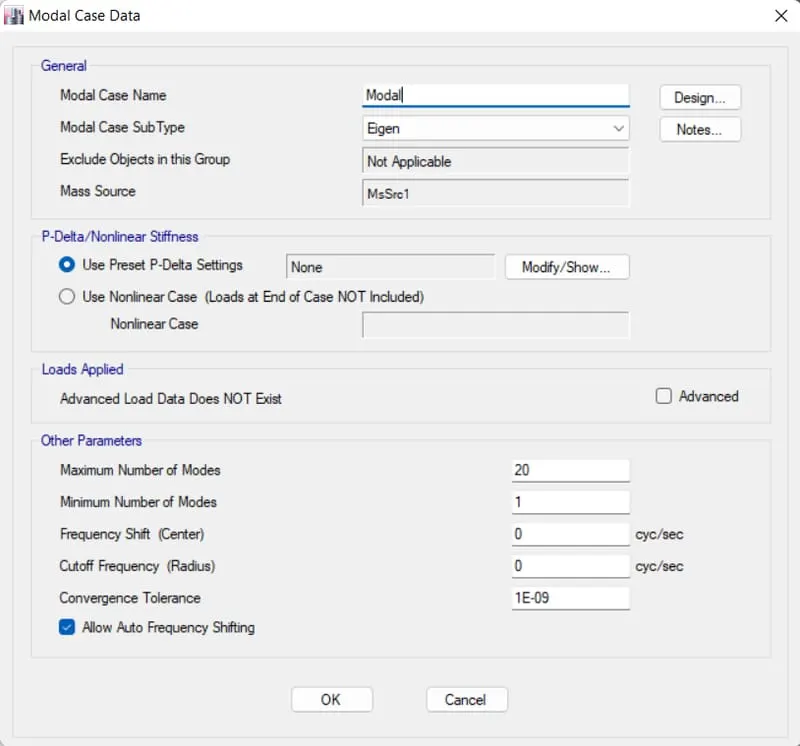
STEP 15 : - Now we have to create a Modal analysis
- For that , define > modal cases > modify
- Enter the data as shown in image.
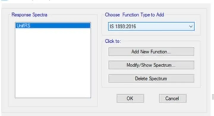
STEP 16: - New function was defined as per the IS1893 for response spectrum analysis.
- After selecting the response spectrum , new tab is visible.
- In that,we choose IS1893:2016 from the "Choose function type"and click on the Modify/Show option as shown below.
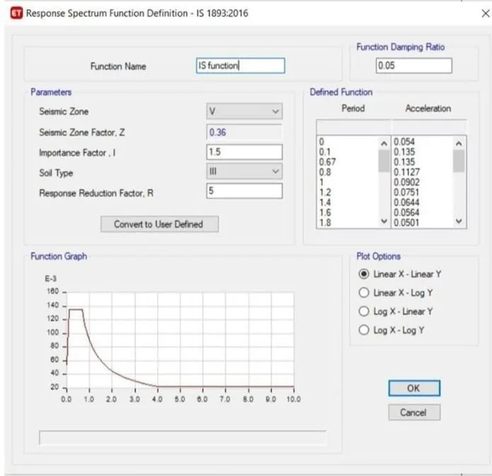
- Two load cases were defined for response spectrum analysis and set default scale factor initially.
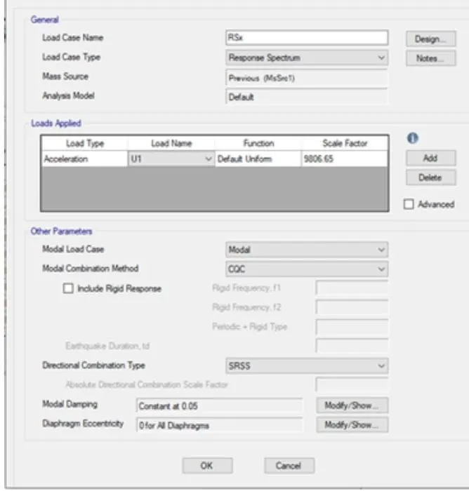
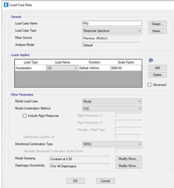
STEP 17: - Now we have to check the model for errors,Go to analysis tab and select check model.

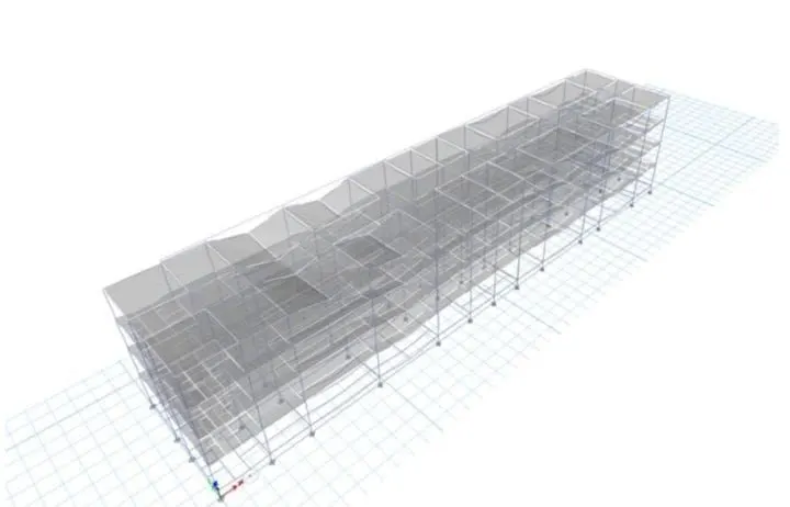
STEP 18: - Now Run the model
- Click on Run analysis
STEP 19:
MODAL PARTICIPATION RATIO : - Modal number check for that go to Display > show tables > analysis results > structure o/p > modal information > modal mass participation ratio.
- According to IS 1873 clause 7.1, the natural period corresponding to fundamental torsional mode of oscillation should not be greater than sum of two fundamental translational mode of oscillation (Tx+Ty>Txy) - from table 0.789 + 0.749 = 1.534 >0.745.Hence no torsional irregularity.
- IS 1873 clause 7.1(table 6),the first three modes contribution should be more than 65% of mass participation factor in each principal plan direction.Here it is 0.71 > 0.65
- Here Tx = 0.789 and Ty = 0.749,differ by 4% hence conclude that building is irregular in mode of oscillation in two principal plan direction.
- From modal number,maximum required is 13 as it captures more than 90% of mass in all 6 degrees of freedom.
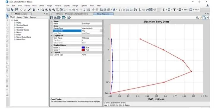
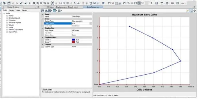
STOREY RESPONSE PLOT: - For this,go to Display > storey response plot > maximum storey drift
- Here storey response for maximum storey drift is less than 0.004 for both X and Y
- Beam design check
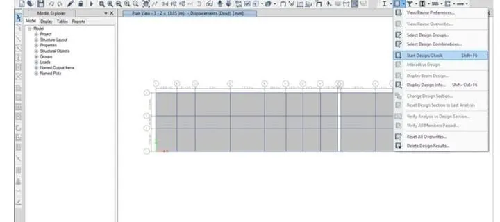
- Click for beam shear reinforcement
- Column longitudinal reinforcement
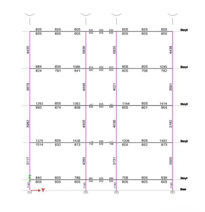
- Column shear reinforcement
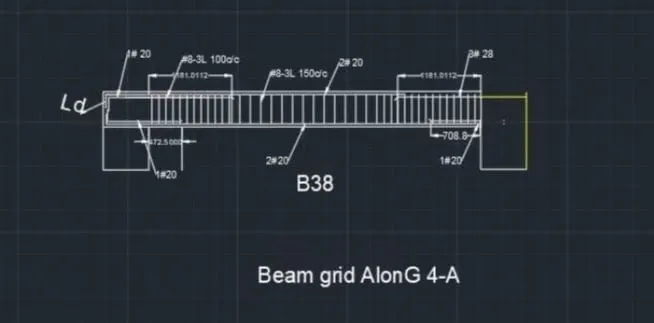
- Beam reinforcement details
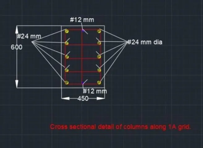
- Column reinforcment details
STEP 1: - In order to export the ETABS model into SAFE,click on file > export >story as SAFE V12.f2k file option.
- Once you click on this option following dialogue box will open
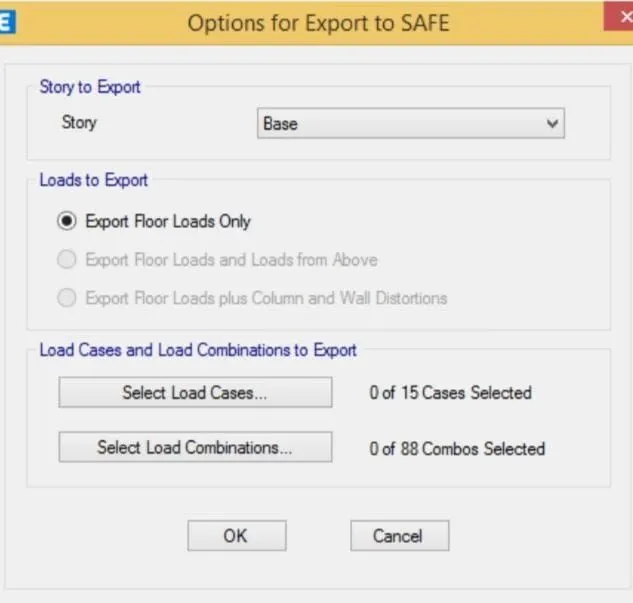
- Select story as Base
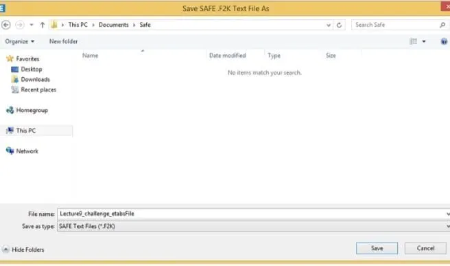
- Now save the file to desired location.
STEP 2:
Given data : - Column of size : 550 x 550mm ii)pile has a load carrying capacity of 280KN
- Pile length - 16m and dia.of pile - 500mm
- SBC - 150KN/m2
STEP 3: - No.of piles = Total axial load/pile capacity = (1.5DL+1.5LL)/280=numbers
- Piles in the springs are defined as spring so for that the spring constant
STEP 4: - k=EA/L
- E=5000(fck)^0.5 = 5000(25)^0.5 = 3.142*(500)^2/4 = 196375m2
- L-10000M
k= 25000*0.7855/16 = 306835.9N/mm - Spacing of the piles as per clause number 6.6.2 of IS 2911
- Spacing between the piles = 2.5 dia.of the piles = 2.5*500 = 1250mm
STEP 5: - We can see that all the grids are exported to the safe.
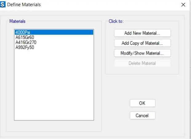
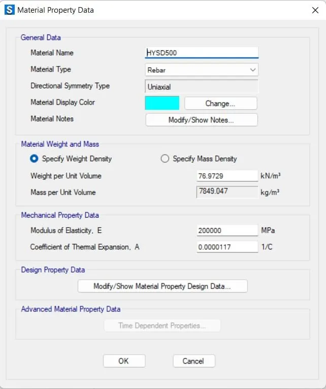
STEP 6: - Now we have to assign Material properties.
- Define > material properties
- Click on add new properties and then add following parameters as shown in image.
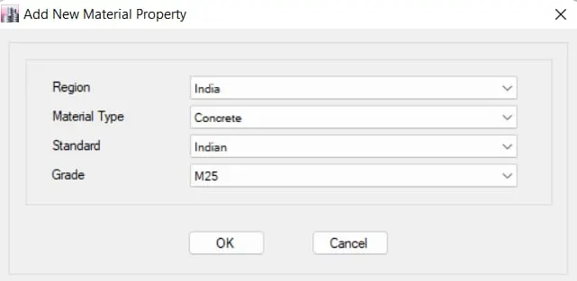
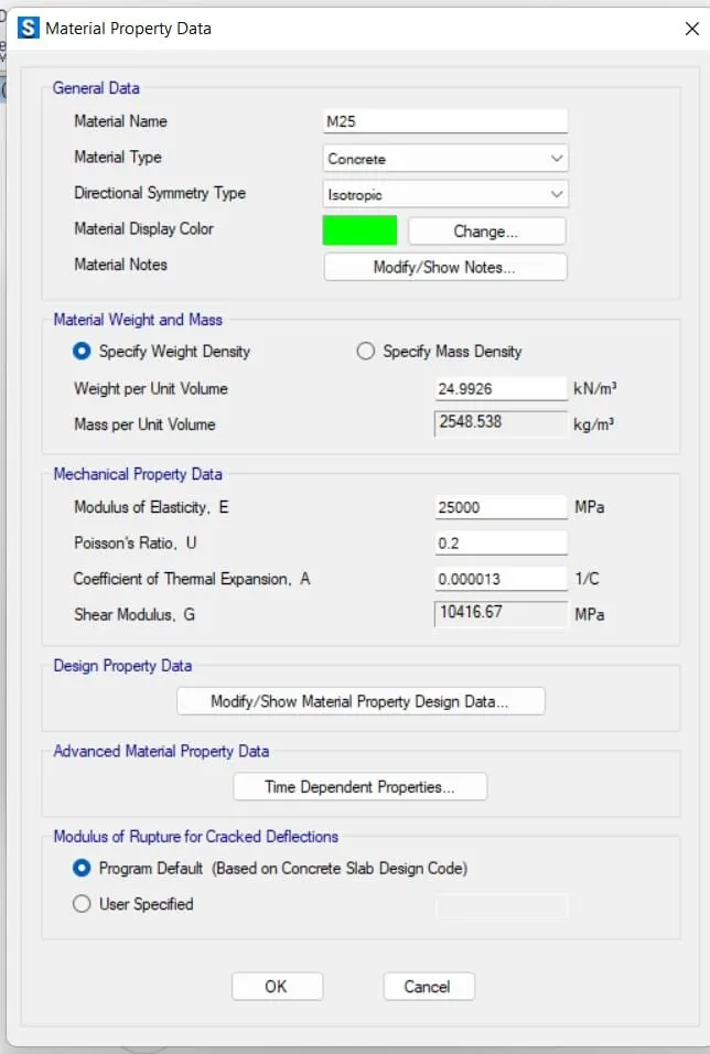
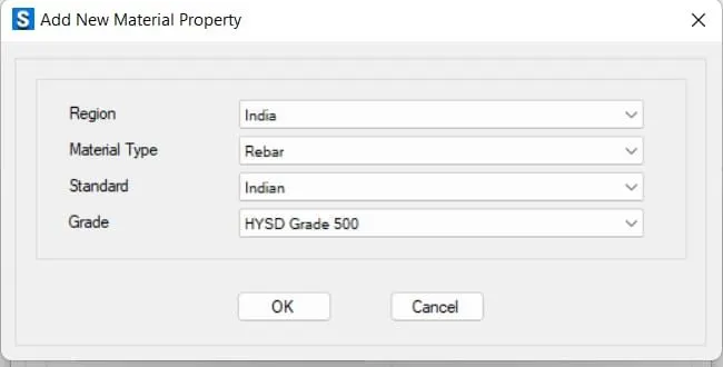
- Similarly add the rebar properties
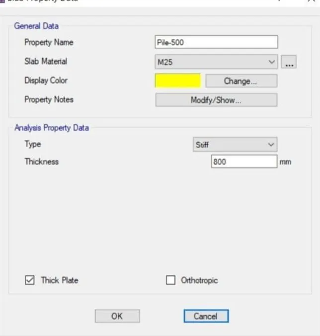
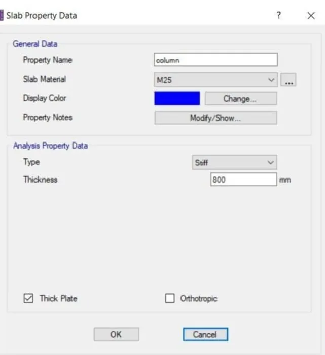
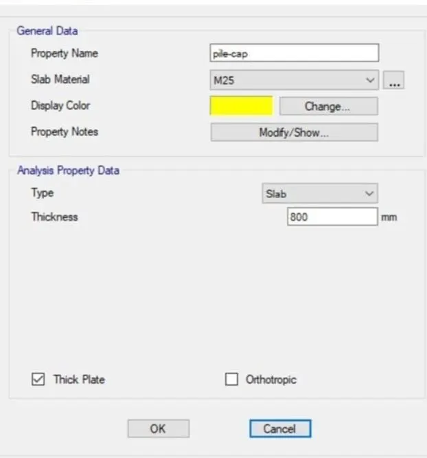
STEP 7: - Now we have to define slab properties
- In pile cap,we have to define 3 slab properties (for pile footing,for column and for pile cap)
STEP 8: - Now we have to start the modelling
- Select Quick draw slab options
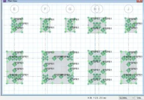
STEP 9: - Now we have to add springs to the pile because it behaves like a spring.
- Click on assign > support data > point springs
- Spring constant from above calculation is taken as
- Add spring constant 419KN/mm
- Select - compression only
STEP 10: - Check the model
- And Run the analysis
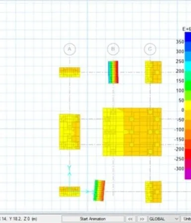
- Check for displacement - we found that displacement is less than allowable settlement i.e.0.825m
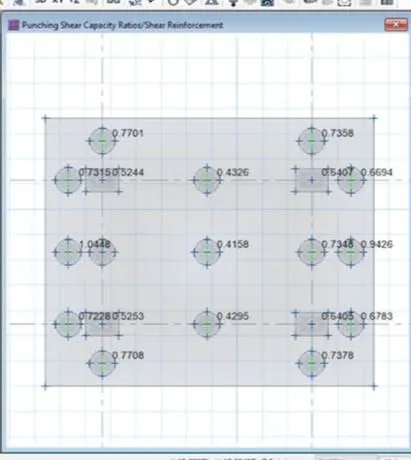
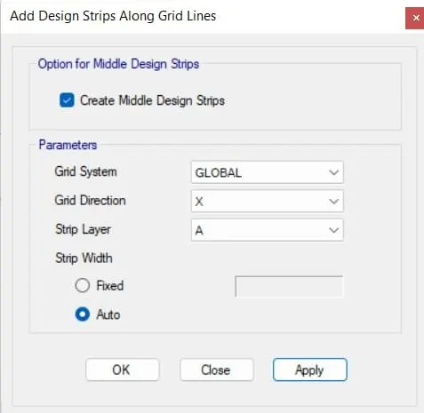
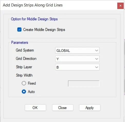
STEP 11: - Now we have to add the design strips
- Click on Edit > Add/edit design strps
- Add the strips in both X and Y direction
STEP 12: - Run the analysis again
- Click on Display > show slab design
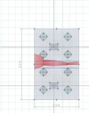
- Similarly in B direction