Project 2_Design & Analysis of a Hostel building at Guwahati, Assam
Que :-
In this project, participants will get to experience the entire design process from modelling, analysis, design, and preparation of construction drawings. The architectural drawings of a G+3 RCC building is provided. The following information on the building is to be used:
- Location – Guwahati, Assam
- Function – Hostel block in an academic institute
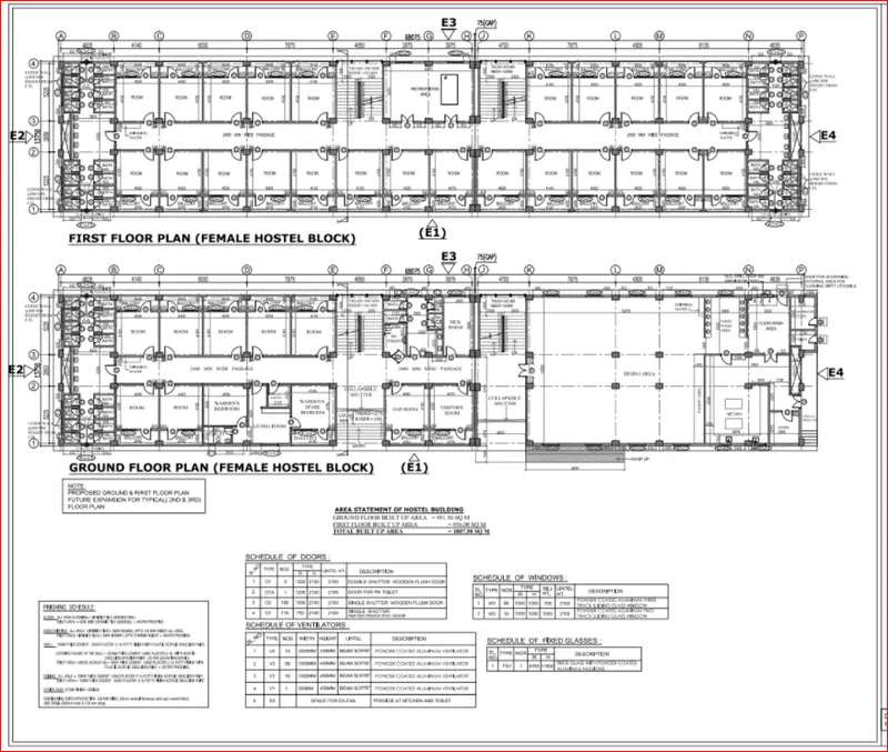
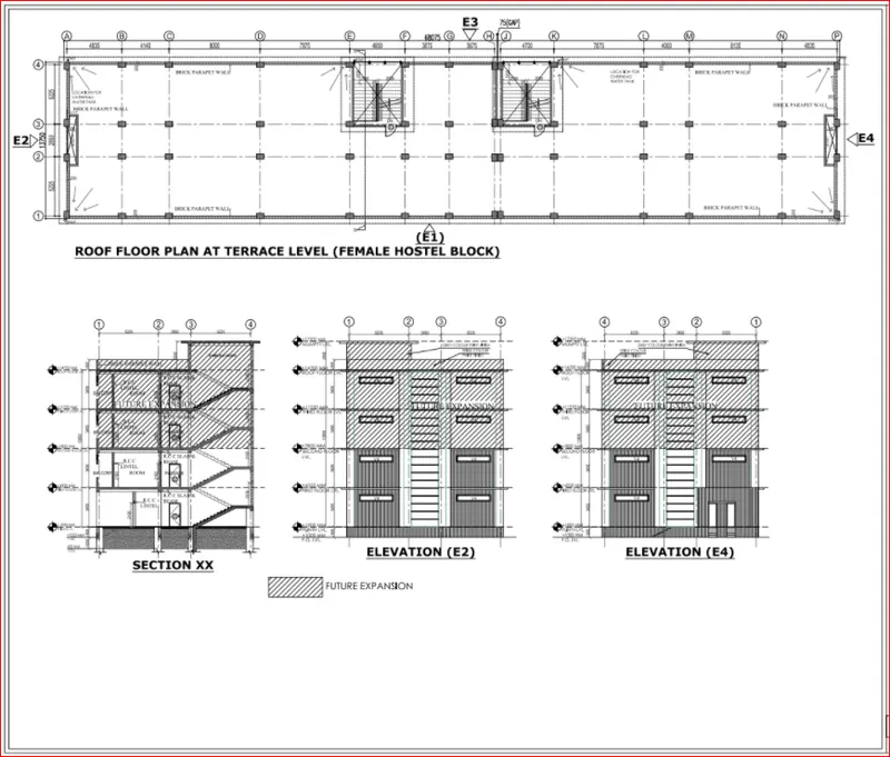
The walls will be made of AAC blocks. Other loadings are to be calculated as per the architectural drawings.
The buildings rests on type 3 soil. Piles of length 10 meters and 500 mm diameter with a load-carrying capacity of 280 KN is to be used.
The ground floor level will be at a height of 2 meters above the existing site level to avoid floodwater enter the building.
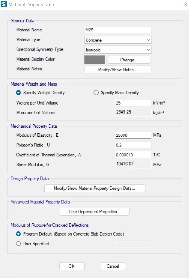
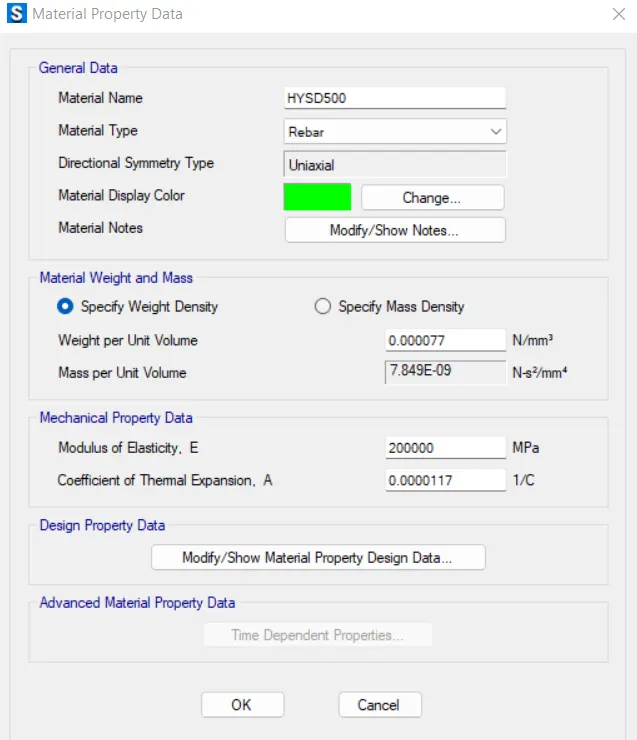
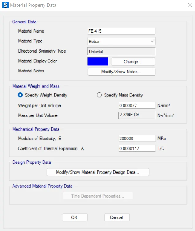
M25 grade of concrete with Fe500 for longitudinal reinforcement and Fe 415 for shear reinforcement is to be used.
The following design IS codes will be required for reference:
- IS 875 part 1
- IS 875 part 2
- IS 13920
- IS 1893
- IS 2911 part 2
- IS 456
- SP 34
Students will have to produce the following:
- Etabs model for the two blocks on either side of the expansion gap
- Foundation details illustrating the pile & pile cap reinforcement
- Tie beam details connecting the pile caps
- Column reinforcement
- Framing plan for typical floor
- Beam reinforcements for ground floor
Ans :-
Design & Analysis Of A Hostel Building At Guwahati Assam
Aim : To design and analyze of G+3 (RCC) Hostel building in ETABS and Foundation in CSI SAFE.
Introduction :-
The procedure for analysis and design of a given building will depend on the type of building its complexity, the number of stories, etc.
First, the architectural drawings of the building are studied, the structural system is finalized sizes of structural members are decided and brought to the knowledge of the concerned architect
The procedure for Structural Design will involve some steps which will depend on the type of building and also its complexity and the time available for structural design.
Often, the work is required to start soon, so the steps in design are to be arranged in such a way the foundation drawings can be taken up in hand within a reasonable period of time.
Further, before starting the structural de;ign, the following information of data are required,
a. A set of architectural drawings;
b. Soil Investigation Report (SIR);
c. Location of the place or city in order to decide on wind and seismic loadings;
d. Data for lifts, water tank capacities on top, special roof features or loadings
Procedure :-
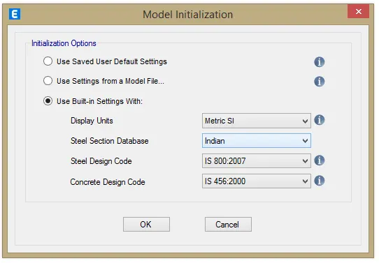
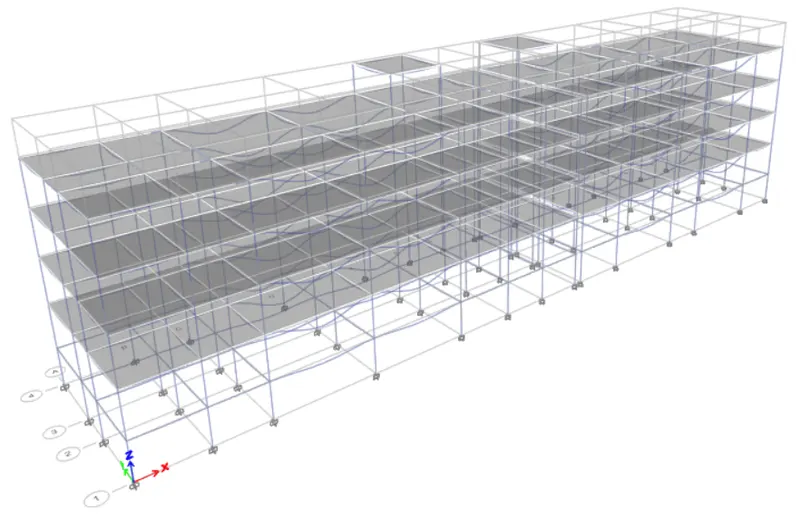
First, we have to open the Etabs software
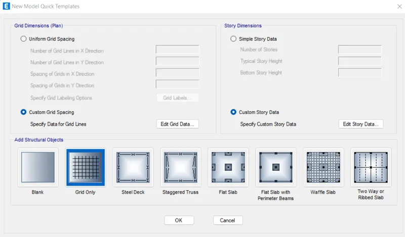
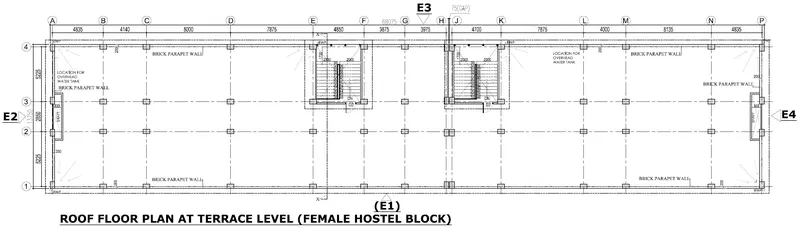
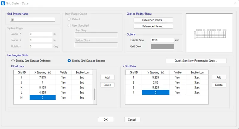
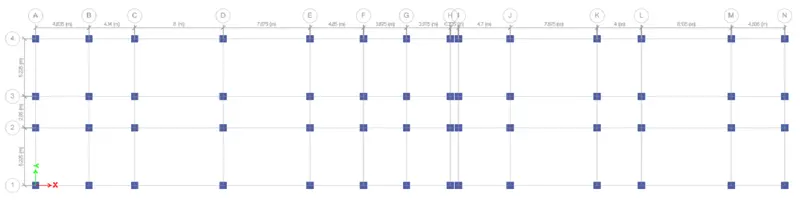
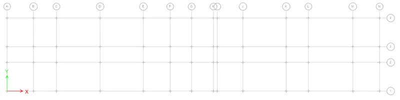
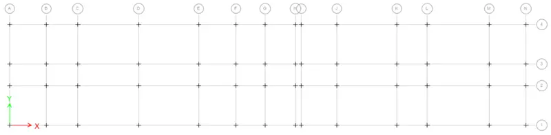
Define the grid Data as spacing- where spacing for X-axis are 4.835m,4.140m,8m,7.875m,4.85m,3.875m,3.975m,0.725m,4.7m,7.875m,4m,8.135m,4.835m (we considered 75mm expansion joint between 3.975m
& 4.7m)
and spacing for Y-axis are (5.225m,2.85m,5.225m) which is given in the architectural drawing-
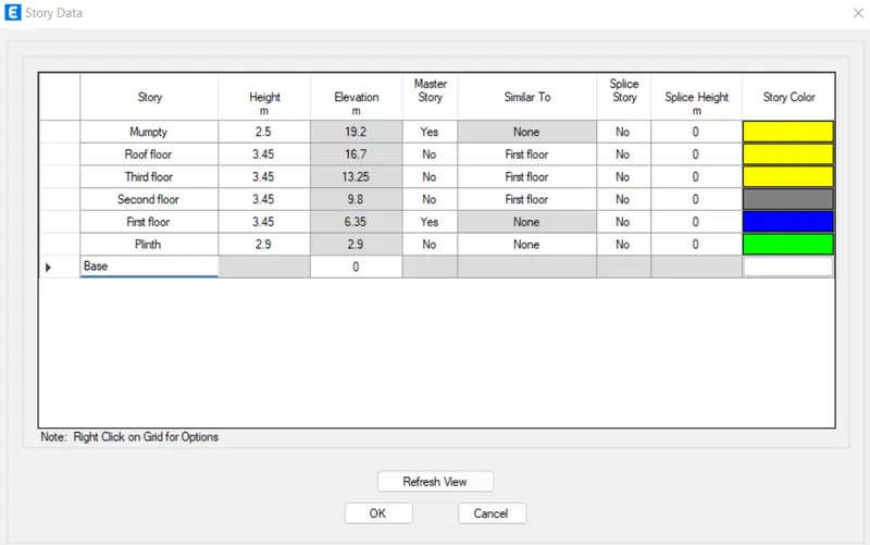
Keep the storey height as per given elevation drawing
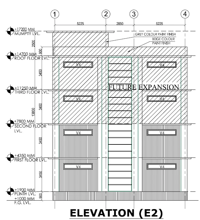
As per given question the ground floor level will be at a height of 2 meters above the existing site level to avoid floodwater enter the building.
Now define the material properties-
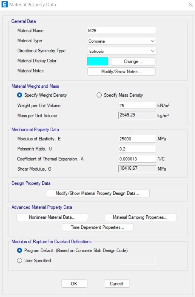
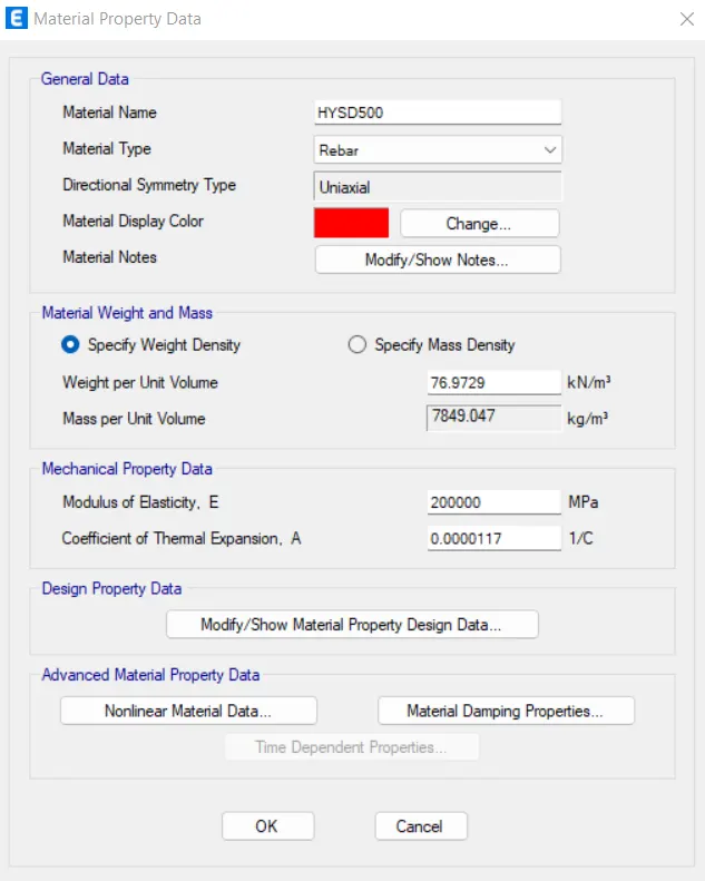
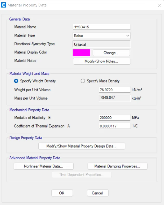
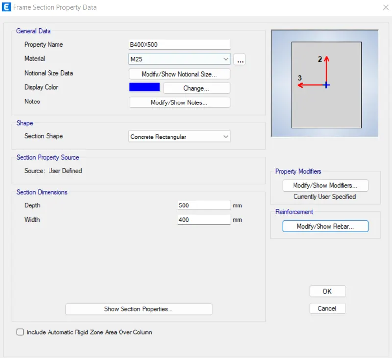
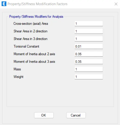
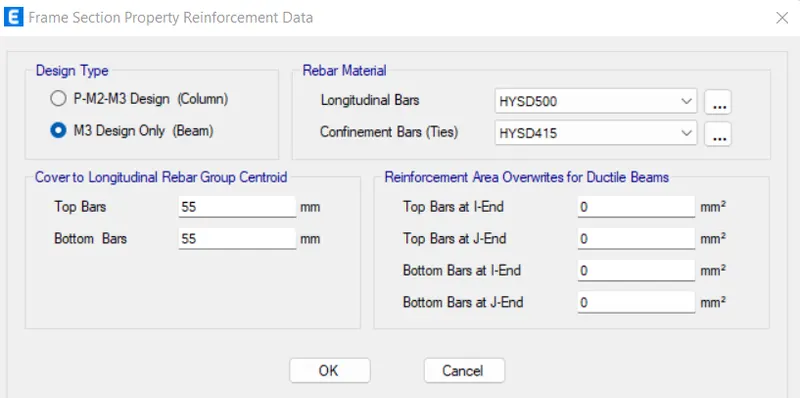
Frame section RC beam assignment-
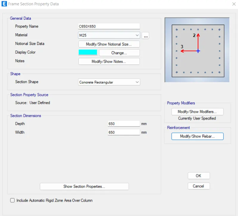
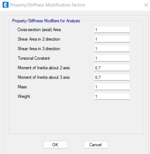
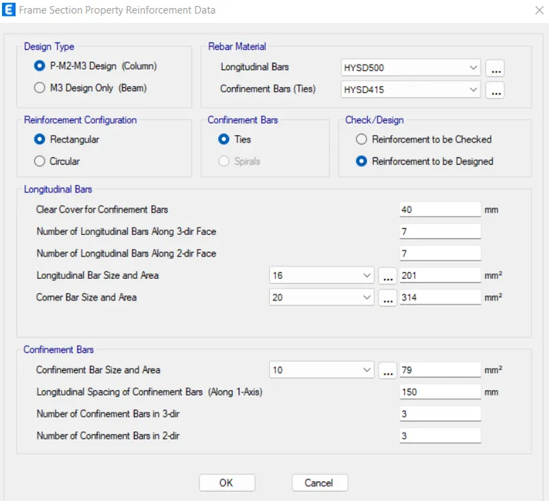
Frame section column assignment-
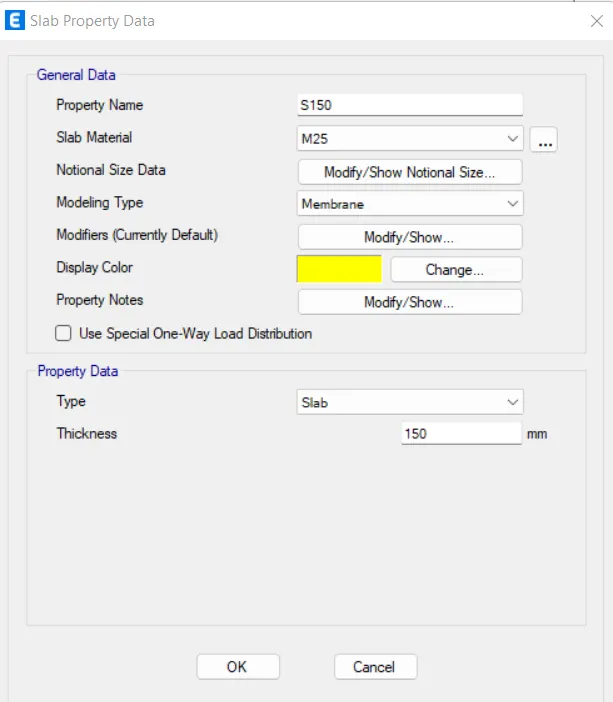
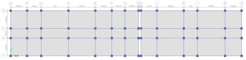
Then assign slab section
Assign the column to the plan
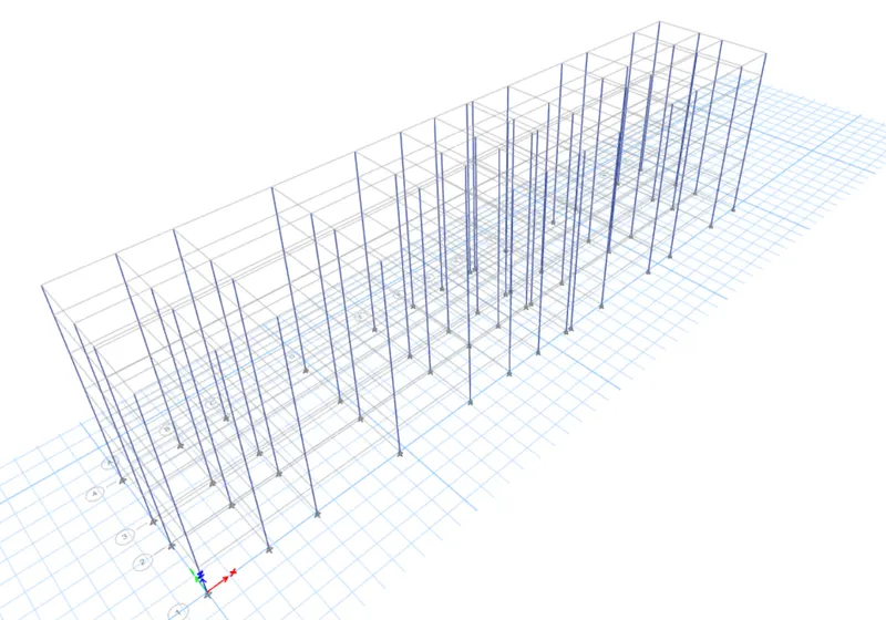
Now assign beams from plinth to roof level
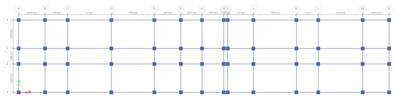
Assign of beam for mumty level
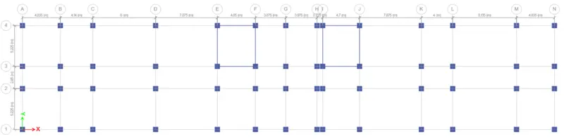
Assign of slab for first floor to roof level-
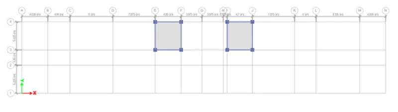
Delete all columns for mumty level except stair supporting columns
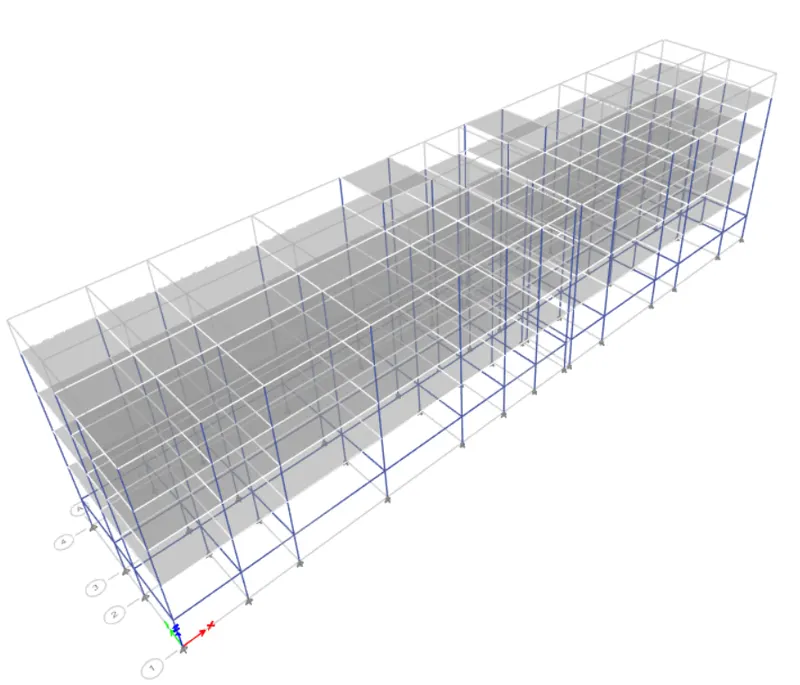
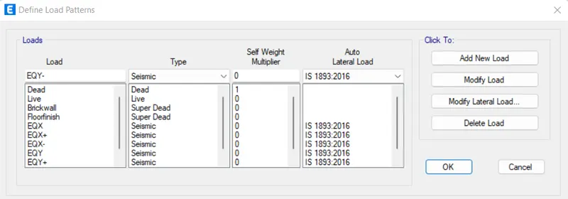
- After placing the elements we need to define the load cases. Define --> load cases --> Provide DL, LL, Eqx, Eqx+, Eqx-, Eqy, Eqy+, Eqy-.
As per IS-1893 Guwahati is in seismic zone-V (zone factor is 0.36)
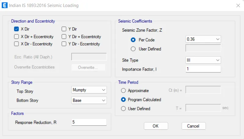
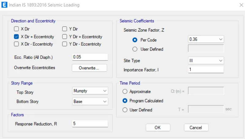
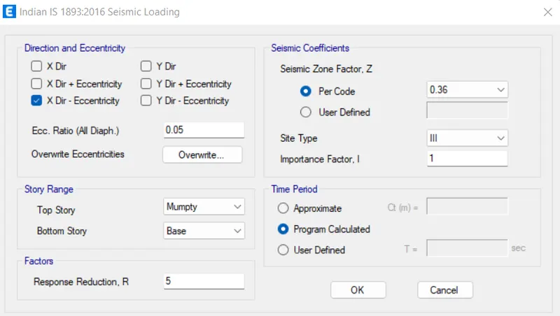
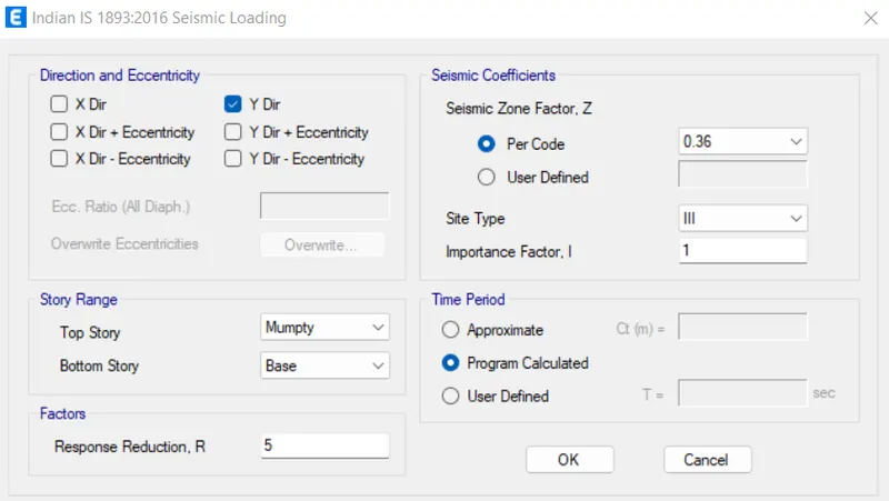
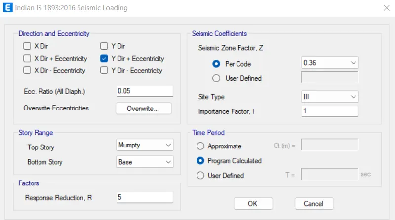
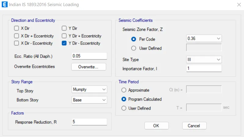
- Now, we need to assign these loads:-
- For live load take the value as 2kN/m2m2 with reference to IS875:part 2.
- Take Brickwall load as 3.5kN/m
- Floor finishes as 1.5kN/m2m2
- Parapet wall load as 1 KN/M
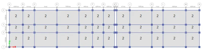
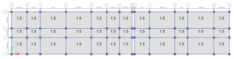
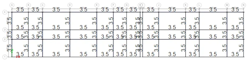
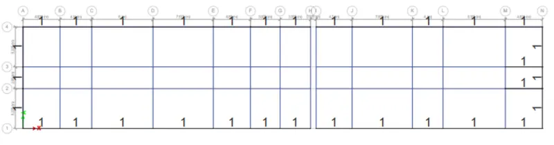
Then define the mass source and response spectrum function.
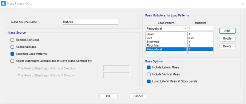
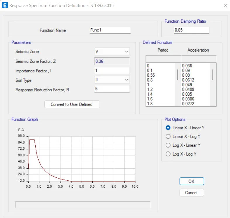
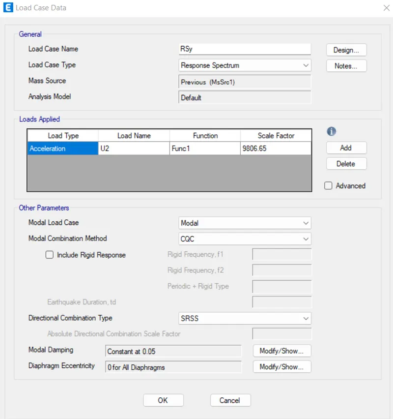
Define load cases and add response spectrum function as RSx and RSy
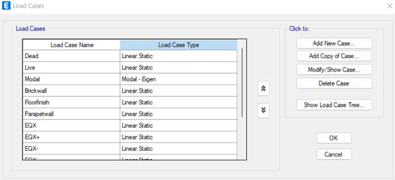
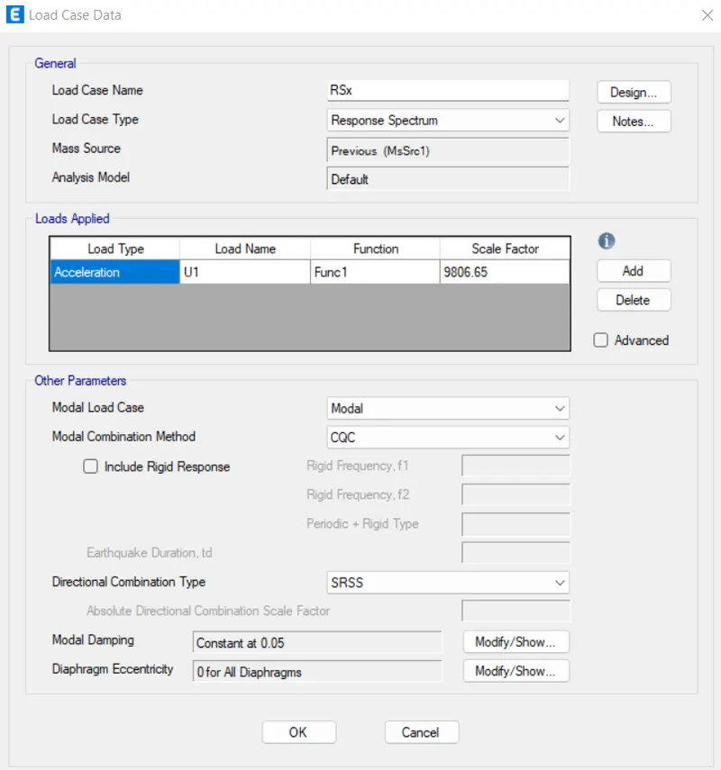
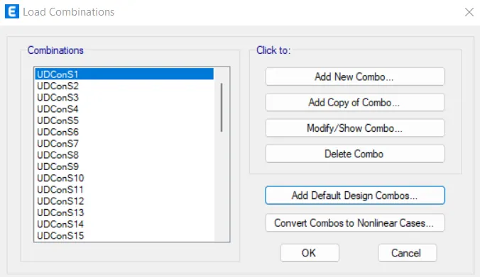
- Then define the load combinations.
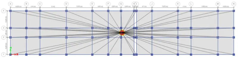
- After that assign diaphragm to the shell.
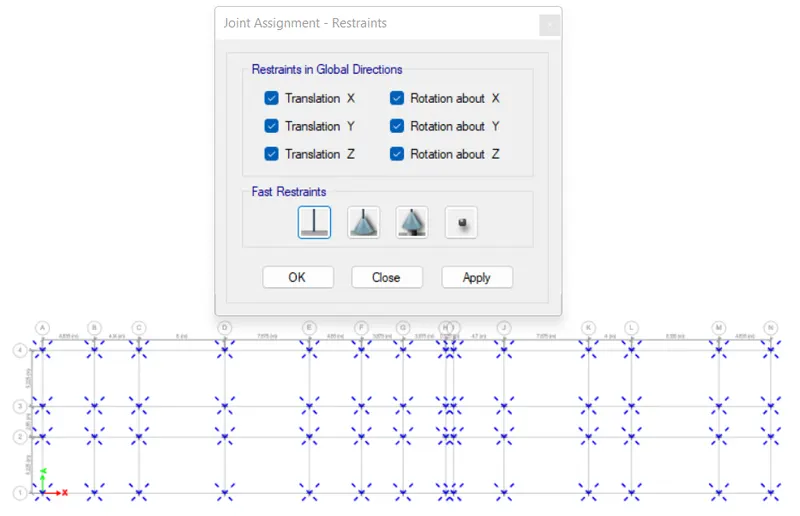
Assign the support (fixed supported) to the base level
Go to Analyze and check model

Run the analysis
- After that we need to check for story drift for RSx and RSy whether it is within the limits or not as per IS1893.
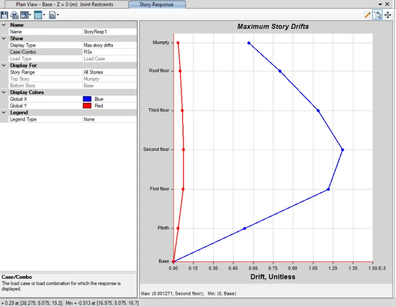
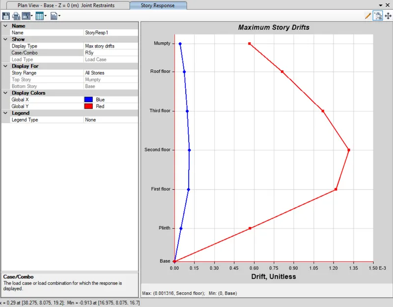
- Hence, both the story drifts are within the codal limits which is 0.004m or 4mm.
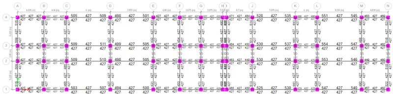
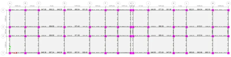
Next we need to carry out the concrete frame design and then extract the design results for beams and columns. Both flexural and shear rebar.
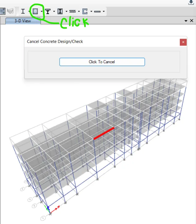
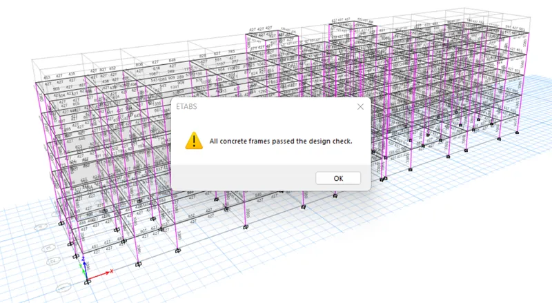
Run the check that all members are passed.
- Beam- longitudinal reinforcement for Ground Floor
- Beam-Shear reinforcement for ground floor
All beams are passed
- Column - Longitudinal reinforcement
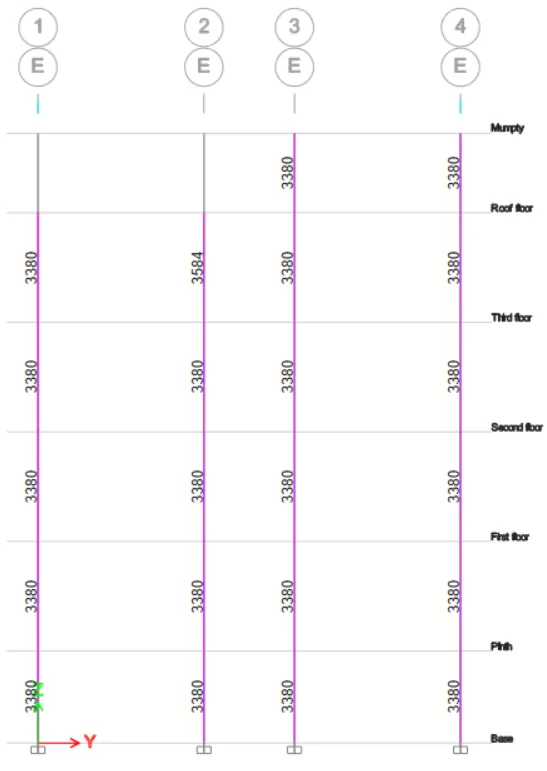
- Column - Shear reinforcement
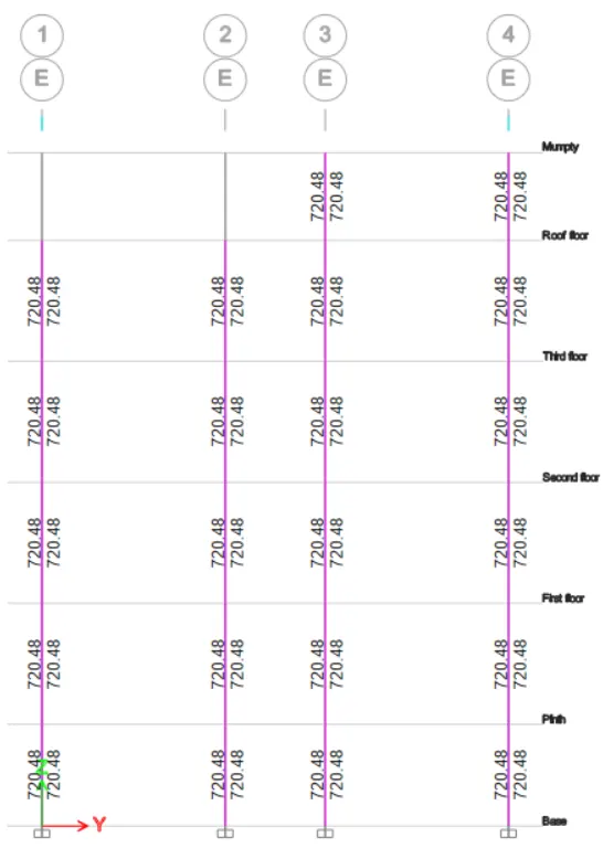
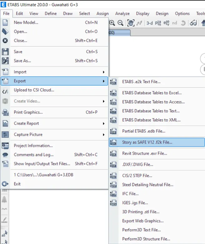
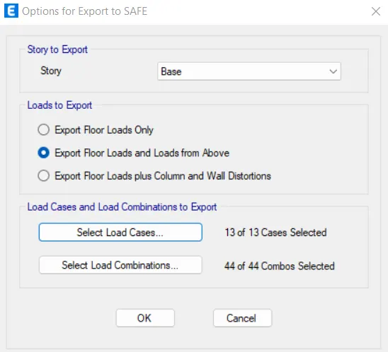
Hence the design is completed. Now, we need to export this Base reactions and load conditions in f2k format for footing design using SAFE software.
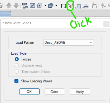
Go to show joints from display option
Show joint force
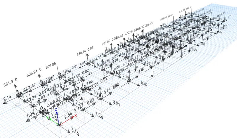
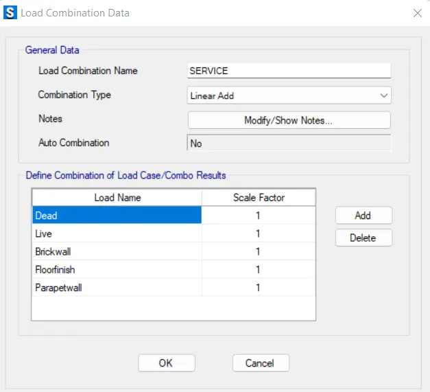
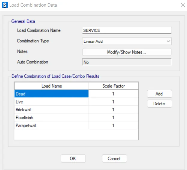
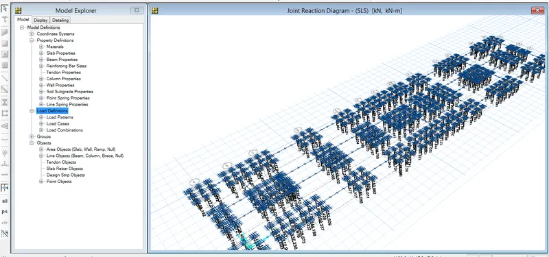
First create a service load combination for getting the combined and acceptable reaction value to design number of pile requirements for each support
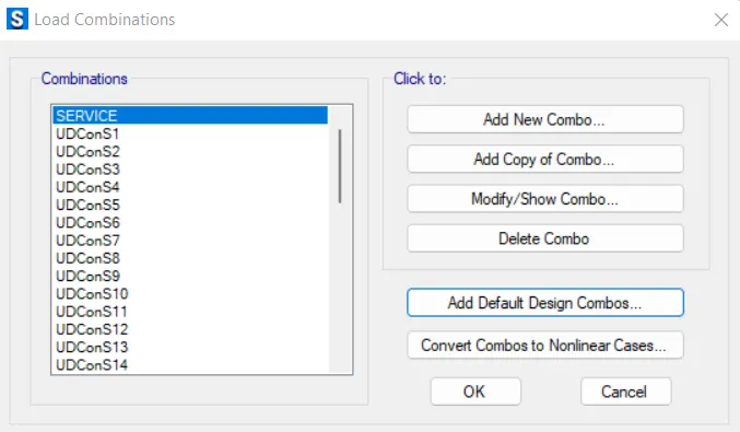
Then select all the joints and assign pin support to each support for getting support reaction
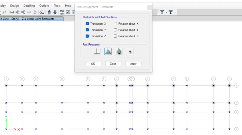
Run the analysis to get the support reaction value and after the analysis
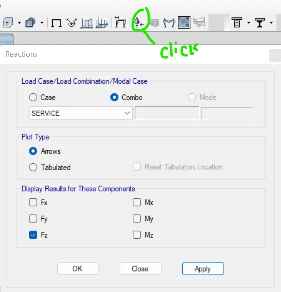
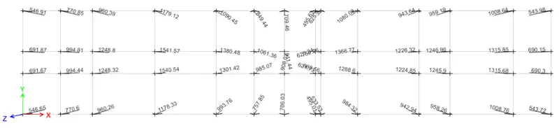
Finally, I have to unlock the model and remove all the pinned supports to no support condition before modeling further.
As on the basis of those above reactions I can crete number of piles-
For the A4 & A1 grid pile-
Axial load = 547 KN
Length of piles 10m
Diameter of pile = 500mm
Pile capacity = 280KN
No of piles = 547/280 = 1.95 = Assume 2 piles
Grade of concrete is M25
Area of each pile = = π4π4X D^2 = 196349.5mm2
E = 5000fck">√fck= 25000
Spring constant (k) = EA/L = (25000 x 196349.5)/10000 = 490873.75 N/mm = 490873.75 Kn/m
Take center to center distance between piles= 2 X Pile diameter(500mm) = 1000mm, edge spacing = 500mm
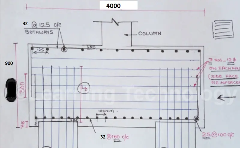
Assume pile cap depth = 900mm
Length = 2000m and Width = 1000mm
I have done the same calculation for rest of the joints to calculate the number of piles under the pile cap
For the A3 & A2 grid pile cap-
Axial load = 692 KN
Pile capacity = 280KN
No of piles = 692/280 = 3.33 = Assume 4 piles
For the B4 & B1 grid pile cap-
Axial load = 771 KN
Pile capacity = 280KN
No of piles = 771/280 = 2.75 = Assume 4 piles
For the B3 & B2 grid pile cap-
Axial load = 995 KN
Pile capacity = 280KN
No of piles = 995/280 = 3.55 = Assume 4 piles
For the C4 & C1 grid pile cap-
Axial load = 961 KN
Pile capacity = 280KN
No of piles = 961/280 = 3.43 = Assume 4 piles
For the C3 & C2 grid pile cap-
Axial load = 1249 KN
Pile capacity = 280KN
No of piles = 1249/280 = 4.46 = Assume 6 piles
For the D1 & D4 grid pile cap-
Axial load = 1180 KN
Pile capacity = 280KN
No of piles = 1180/280 = 4.21 = Assume 6 piles
For the D3 & D2 grid pile cap-
Axial load = 1542 KN
Pile capacity = 280KN
No of piles = 1542/280 = 5.5 = Assume 6 piles
For the E4 grid pile cap-
Axial load = 1091 KN
Pile capacity = 280KN
No of piles = 1091/280 = 3.89 = Assume 4 piles
For the E1 grid pile cap-
Axial load = 994 KN
Pile capacity = 280KN
No of piles = 994/280 = 3.55 = Assume 4 piles
For the E3 grid pile cap-
Axial load = 1381 KN
Pile capacity = 280KN
No of piles = 1381/280 = 4.93 = Assume 6 piles
For the E2 grid pile cap-
Axial load = 1302 KN
Pile capacity = 280KN
No of piles = 1302/280 = 4.65 = Assume 6 piles
For the F4 grid pile cap-
Axial load = 850 KN
Pile capacity = 280KN
No of piles = 850/280 = 3.03 = Assume 4 piles
For the F3 grid pile cap-
Axial load = 1062 KN
Pile capacity = 280KN
No of piles = 1062/280 = 3.79 = Assume 4 piles
For the F2 grid pile cap-
Axial load = 985 KN
Pile capacity = 280KN
No of piles = 985/280 = 3.52 = Assume 4 piles
For the F1 grid pile cap-
Axial load = 758 KN
Pile capacity = 280KN
No of piles = 758/280 = 2.70 = Assume 4 piles
For the G4 grid pile cap-
Axial load = 710 KN
Pile capacity = 280KN
No of piles = 710/280 = 2.53 = Assume 4 piles
For the G3 grid pile cap-
Axial load = 912 KN
Pile capacity = 280KN
No of piles = 912/280 = 3.26 = Assume 4 piles
For the G2 grid pile cap-
Axial load = 908 KN
Pile capacity = 280KN
No of piles = /280 = 3.24 = Assume 4 piles
For the G1 grid pile cap-
Axial load = 706 KN
Pile capacity = 280KN
No of piles = 706/280 = 2.52 = Assume 4 piles
For the H4 & H1 grid pile cap-
Axial load = 496 KN
Pile capacity = 280KN
No of piles = 496/280 = 1.77 = Assume 2 piles
For the H3 & H2 grid pile cap-
Axial load = 623 KN
Pile capacity = 280KN
No of piles = 623/280 = 2.22 = Assume 4 piles
For the I4 grid pile cap-
Axial load = 626 KN
Pile capacity = 280KN
No of piles = 626/280 = 2.23 = Assume 4 piles
For the I3 grid pile cap-
Axial load = 760 KN
Pile capacity = 280KN
No of piles = 760/280 = 2.71 = Assume 4 piles
For the I2 grid pile cap-
Axial load = 681 KN
Pile capacity = 280KN
No of piles = 681/280 = 2.43 = Assume 4 piles
For the I1 grid pile cap-
Axial load = 534 KN
Pile capacity = 280KN
No of piles = 534/280 = 1.90 = Assume 2 piles
For the J4 grid pile cap-
Axial load = 1080 KN
Pile capacity = 280KN
No of piles = 1080/280 = 3.86 = Assume 4 piles
For the J3 grid pile cap-
Axial load = 1367 KN
Pile capacity = 280KN
No of piles = 1367/280 = 4.88 = Assume 6 piles
For the J2 grid pile cap-
Axial load = 1289 KN
Pile capacity = 280KN
No of piles = 1289/280 = 4.61 = Assume 6 piles
For the J1 grid pile cap-
Axial load = 985 KN
Pile capacity = 280KN
No of piles = 985/280 = 3.52 = Assume 4 piles
For the K4 grid pile cap-
Axial load = 944 KN
Pile capacity = 280KN
No of piles = 944/280 = 3.37 = Assume 4 piles
For the K3 & K2 grid pile cap-
Axial load = 1227 KN
Pile capacity = 280KN
No of piles = 1227/280 = 4.38 = Assume 6 piles
For the K1 grid pile cap-
Axial load = 943 KN
Pile capacity = 280KN
No of piles = 943/280 = 3.37 = Assume 4 piles
For the L4 & L1 grid pile cap-
Axial load = 960 KN
Pile capacity = 280KN
No of piles = 960/280 = 3.89 = Assume 4 piles
For the L3 & L2 grid pile cap-
Axial load = 1247 KN
Pile capacity = 280KN
No of piles = 1247/280 = 4.45 = Assume 6 piles
For the M4 & M1 grid pile cap-
Axial load = 1009 KN
Pile capacity = 280KN
No of piles = 1009/280 = 3.60 = Assume 4 piles
For the M3 & M2 grid pile cap-
Axial load = 1316 KN
Pile capacity = 280KN
No of piles = 1316/280 = 4.7 = Assume 6 piles
For the N4 & N1 grid pile cap-
Axial load = 544 KN
Pile capacity = 280KN
No of piles = 544/280 = 1.94 = Assume 2 piles
For the N3 & N2 grid pile cap-
Axial load = 691 KN
Pile capacity = 280KN
No of piles = 691/280 = 2.46 = Assume 4 piles
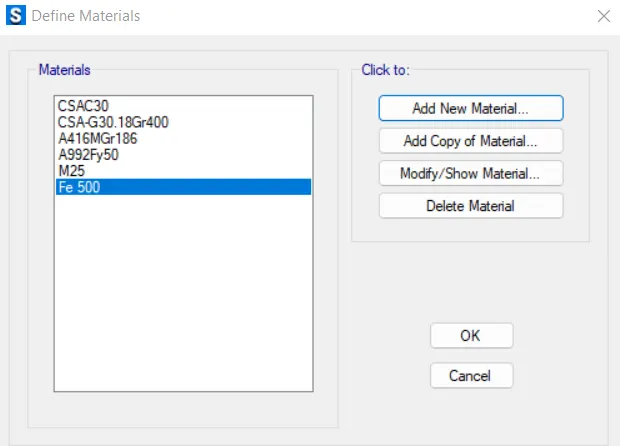
Define materials
- Define slab properties.
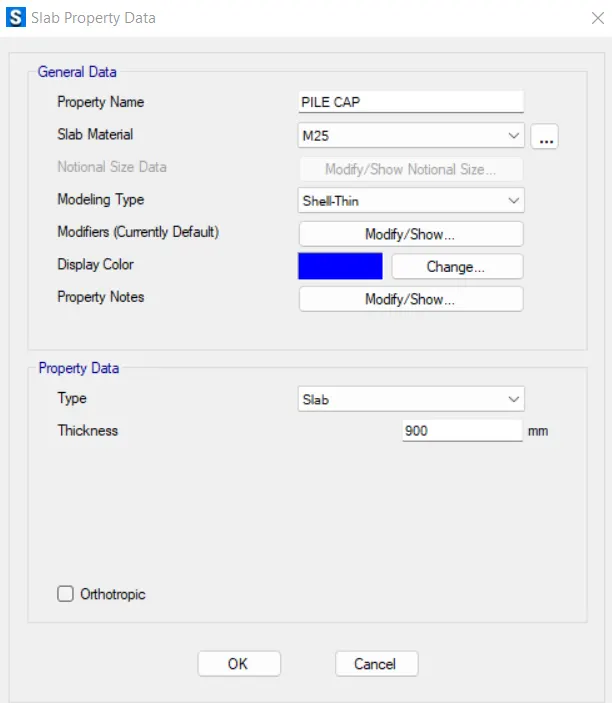
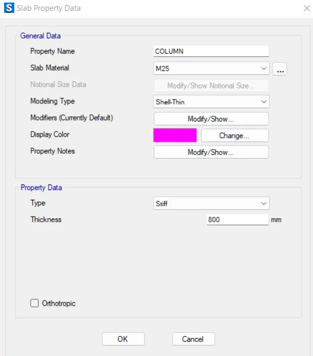
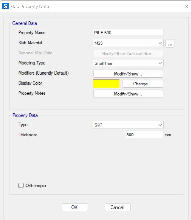
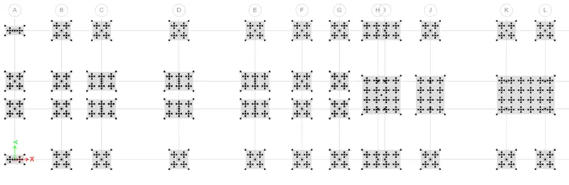
- After that using draw point option drop the points for footing for each column.
- Now, go to draw option and draft points on footing for the piles to be developed.
- Next we need to provide pile, using the above used option and material property as pile500.
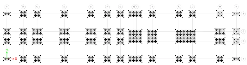
- Then place, the column along grid intersections.
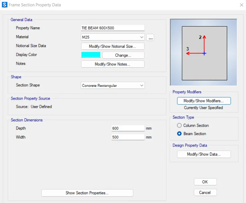
- Define beam for tie beams.
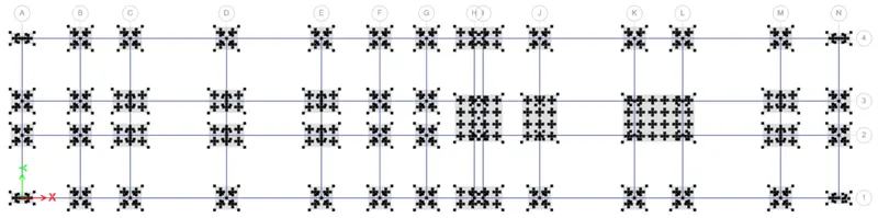
ASSIGN THE SPRING CONSTANT
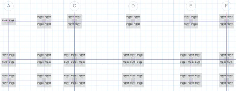
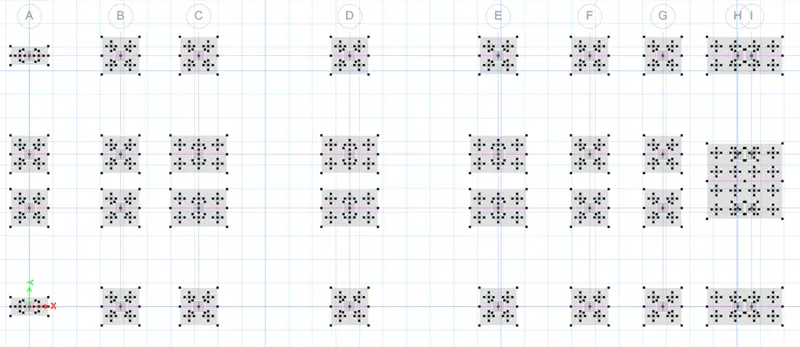
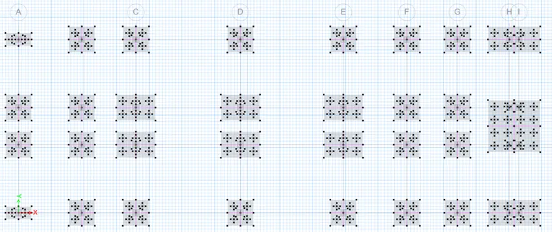
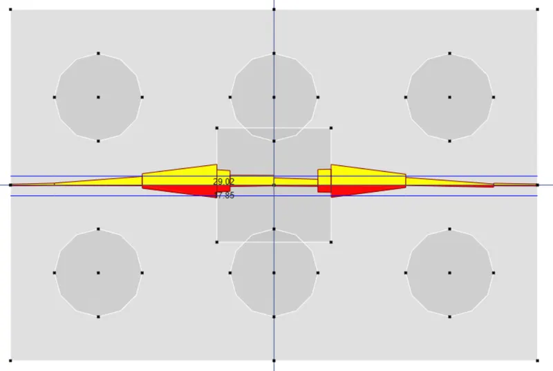
- Now, we need to design the strip.
- Now, again carryout the design.
- For strip layer A
- For strip layer B
DEFINE THE LOAD COMBINATION
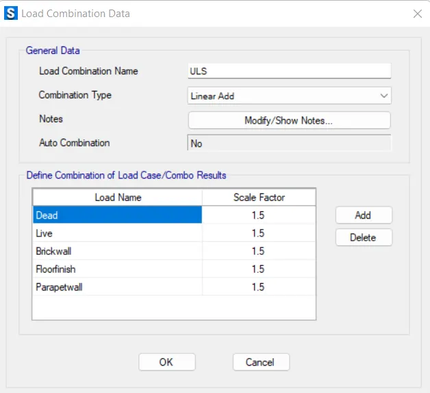
Assign the load combination to Ultimate limit state
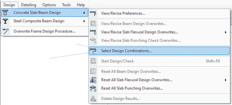
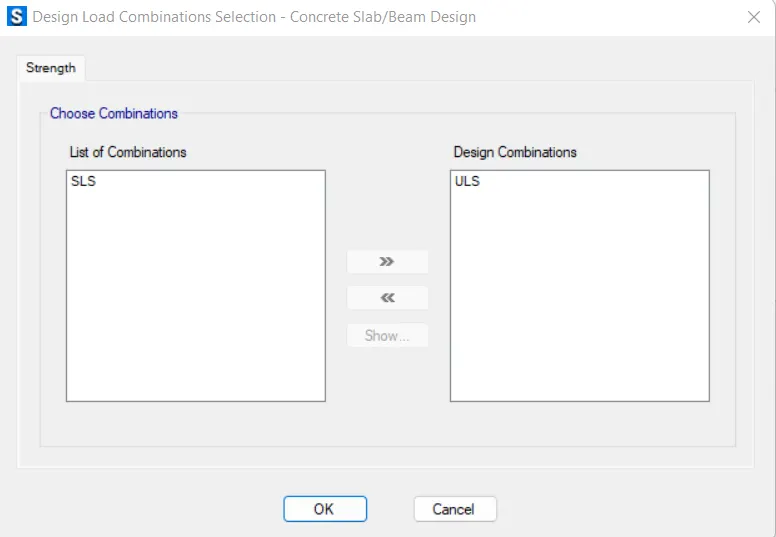
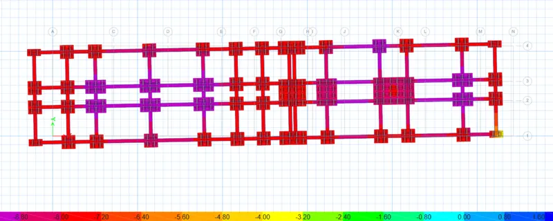
RUN THE ANALYSIS
- Displacement values are within the limit, hence safe.
- Reaction check :
- Punching shear values are also within the range
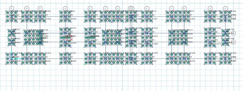
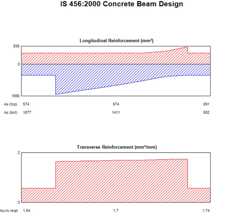
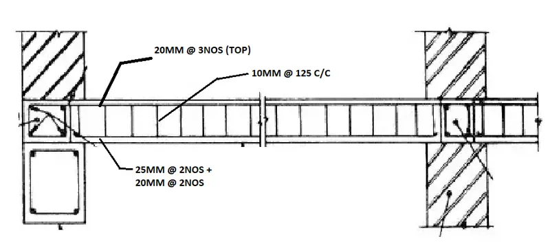
- LONGITUDINAL REINFORCEMENT DETAILS FOR TIE BEAM
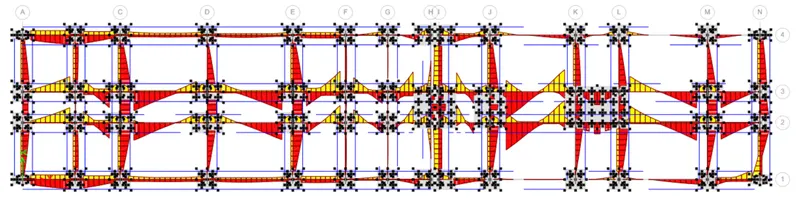
- Hence, the design of footing is completed.
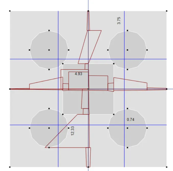
PILE CAP DESIGN DETAILS
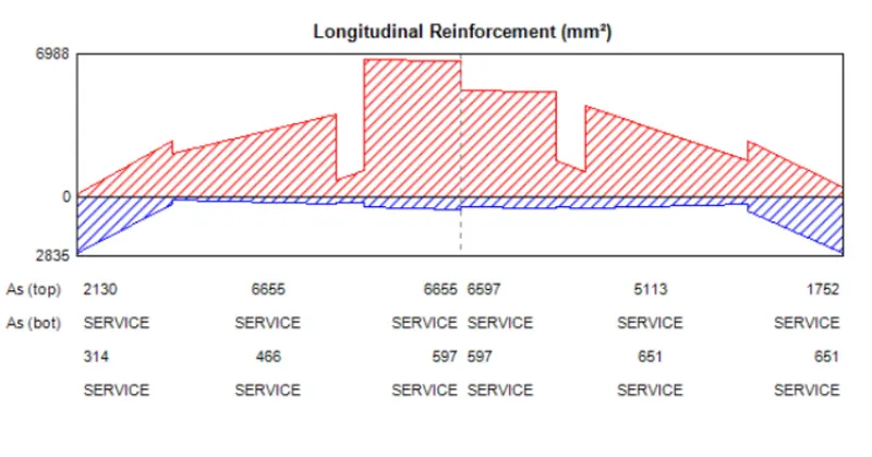
TIE BEAM DESIGN
Result:-
Modelling, analysis and design of G+3 building has been carried out successfully using ETABS software and the foundation design(Pile cap and pile) has also been carried out using SAFE software.
Reinforcement details associated with modelling has also been included.
Also all the required details are provided according to the mentioned list-
- Etabs model for the two blocks on either side of the expansion gap
- Foundation details illustrating the pile & pile cap reinforcement
- Tie beam details connecting the pile caps
- Column reinforcement
- Framing plan for typical floor
- Beam reinforcements for ground floor