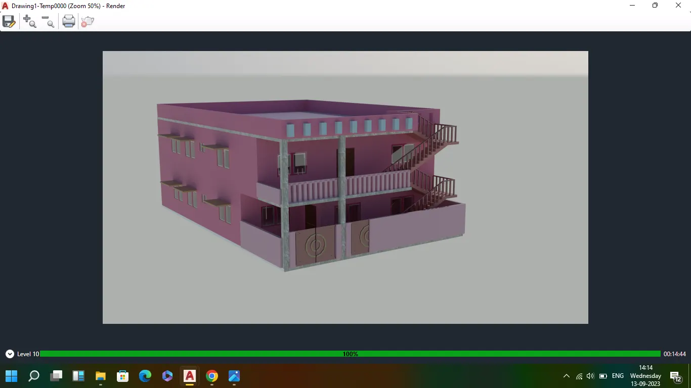
Project 2_Creating a 3D rendered model for a Residential Building in AutoCad
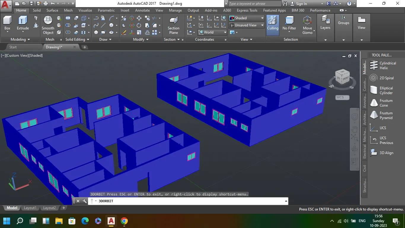
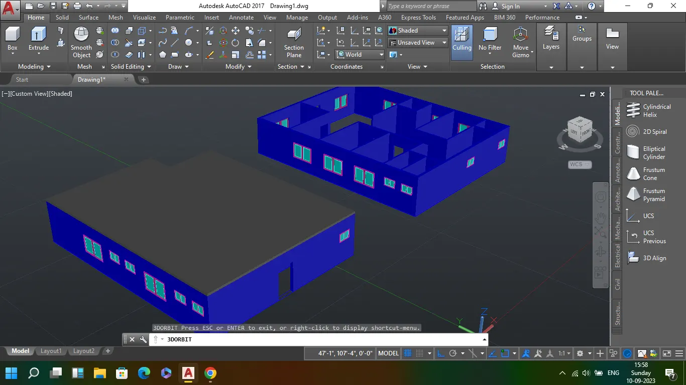
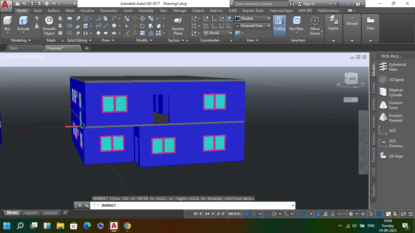
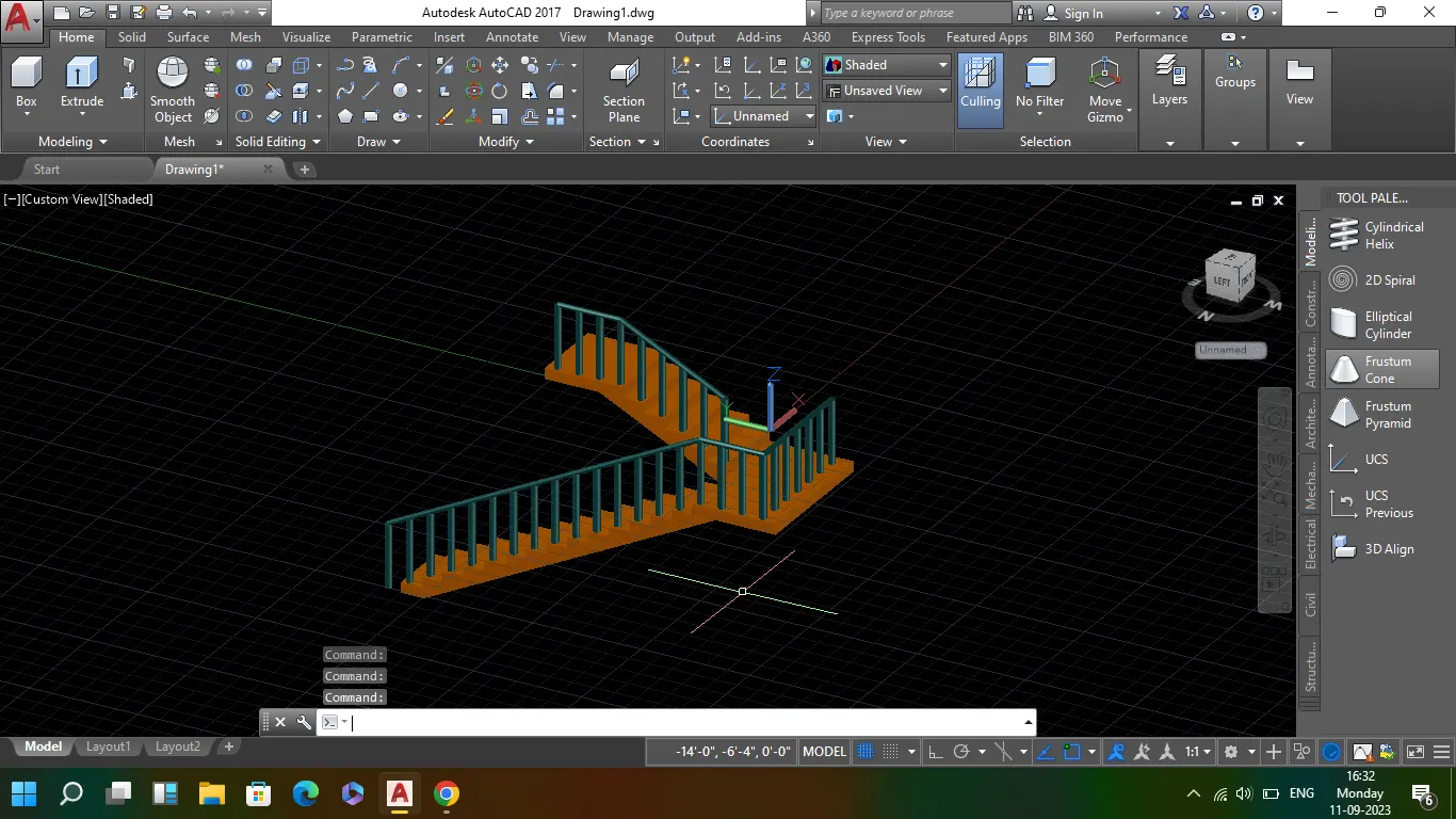
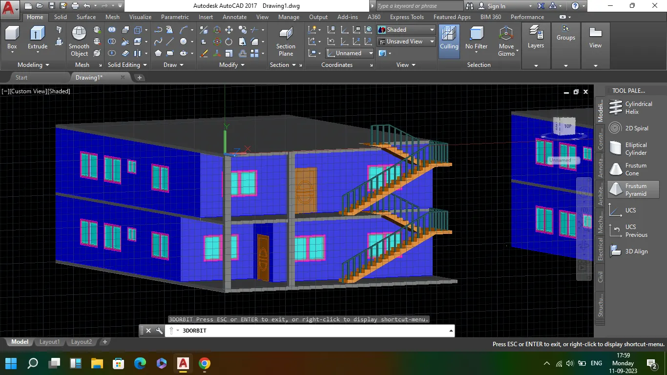
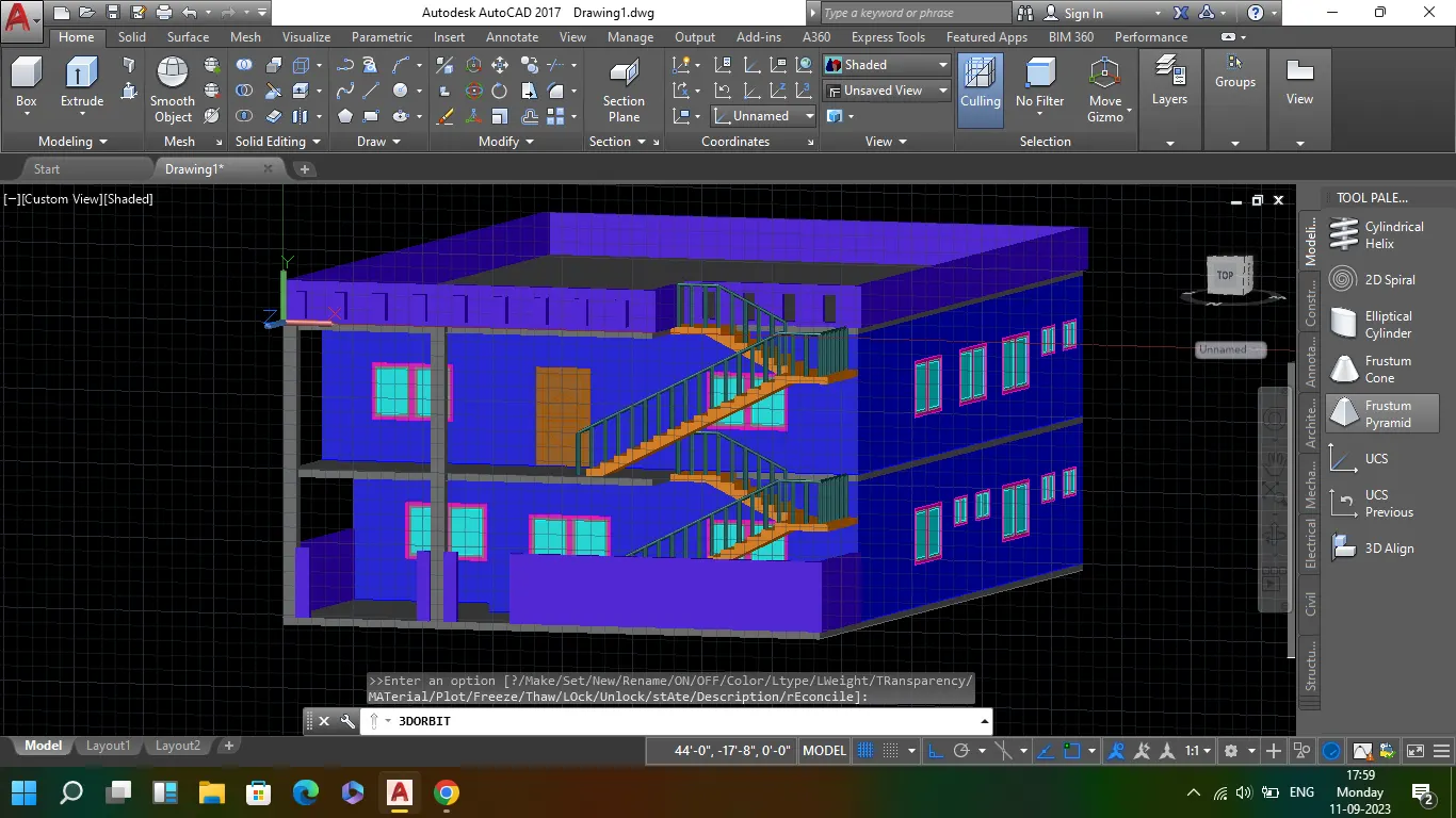
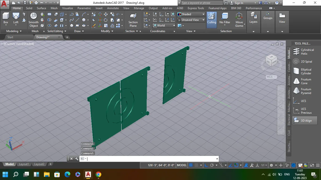
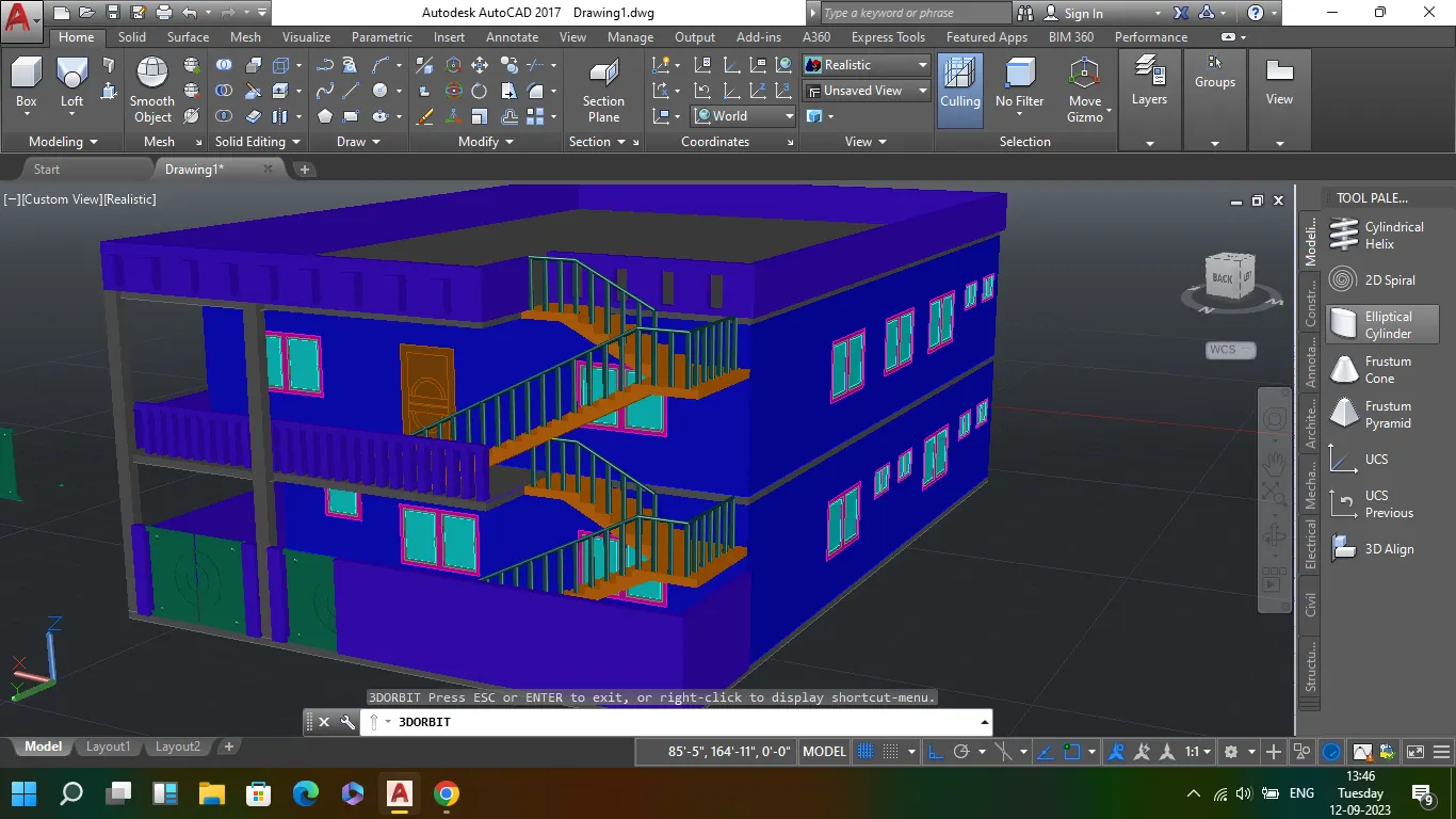
Aim : to create the 3d model of residential building and render it
Introduction :
here we use the basic tools and commands of autocad software to create the 3D model of building
tools and commands like line, polyline, extrude, substract, layers, trim, erase, move, copy, rotate, 3D rotate, 3D array, dimlinear, dimesnsion, texts, materials, render, UCS, and many
using all the above commands and with proper engineering skills of dimensioning and planning a model is created.
Procedure :
- Open the new dwg file, units command: here set to engineering and inches, limits command :set the required limits of the page, zoom command : zoom the dwg file to required size
- select the modeling type to 3D modeling and begin with the dwg.
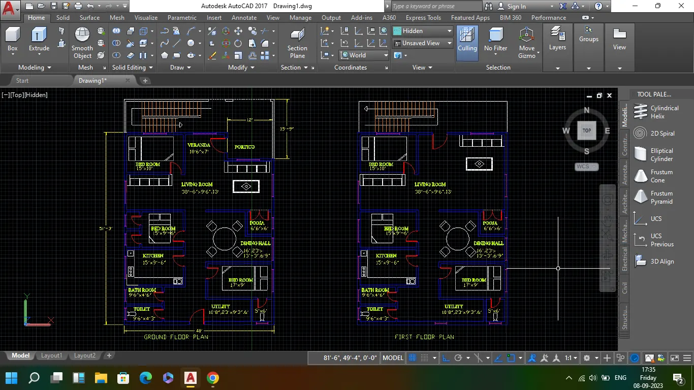
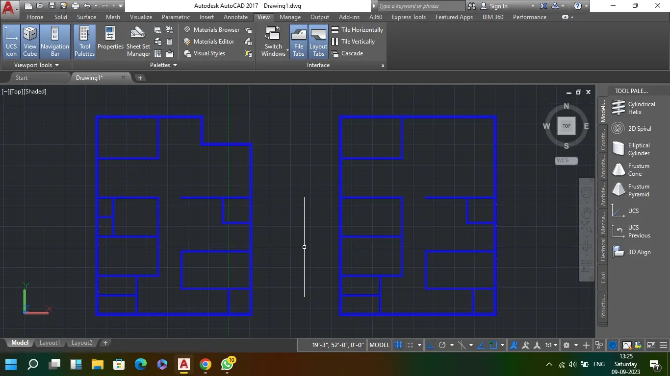
- draw the 2D plan of the ground floor and first floor on the xy plane with all the dimension, along with thise draw the stairs and all reqired components
- once all the 2D components are drawn assign all the components in different layers with different colours
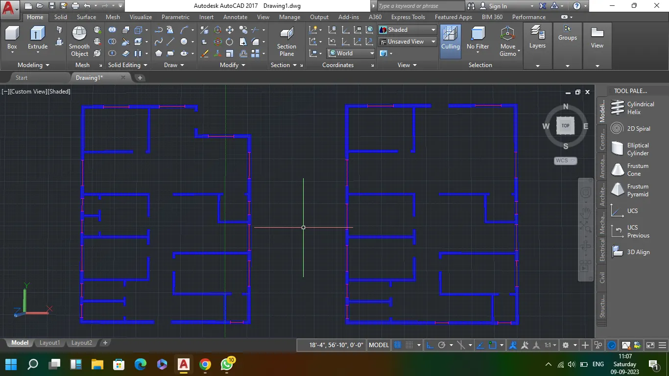
- by using Boundry command assign all the walls in to region
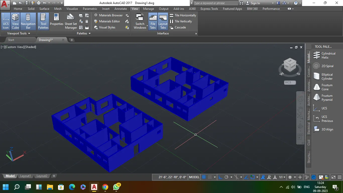
- using Extrude command extrude the walls of both floors to required height and using substract command substract window space and door space and put the drawing in isometric view
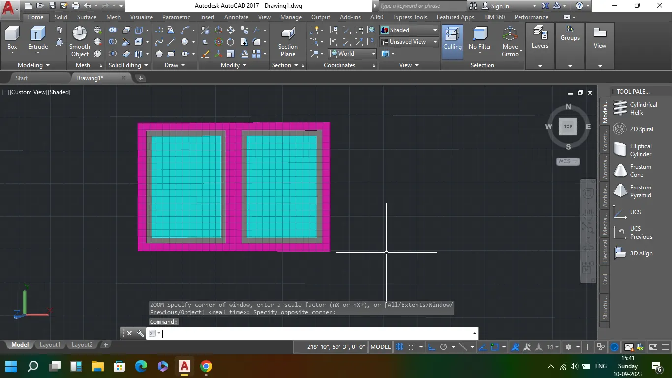
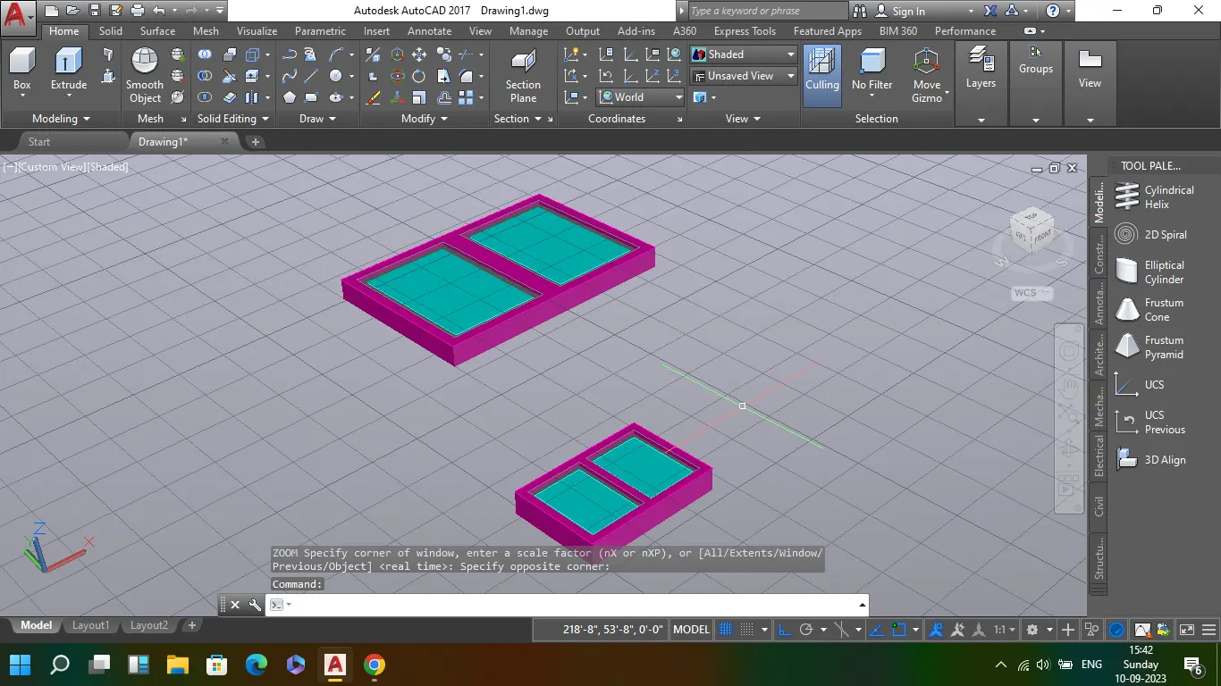
- to create the 3d model of window draw a rectangle in xy plane and offset it for window frame, mullion and glass. Using boundary command region for frame, mullion and glass using respective layers and extrude the frame, mullion and glass.
- Copy the 3d window and place it to the window space in the wall and do same as that for door of the building, draw the rectangle over the windows using UCS and extrude the rect so the it will be chajja for the window
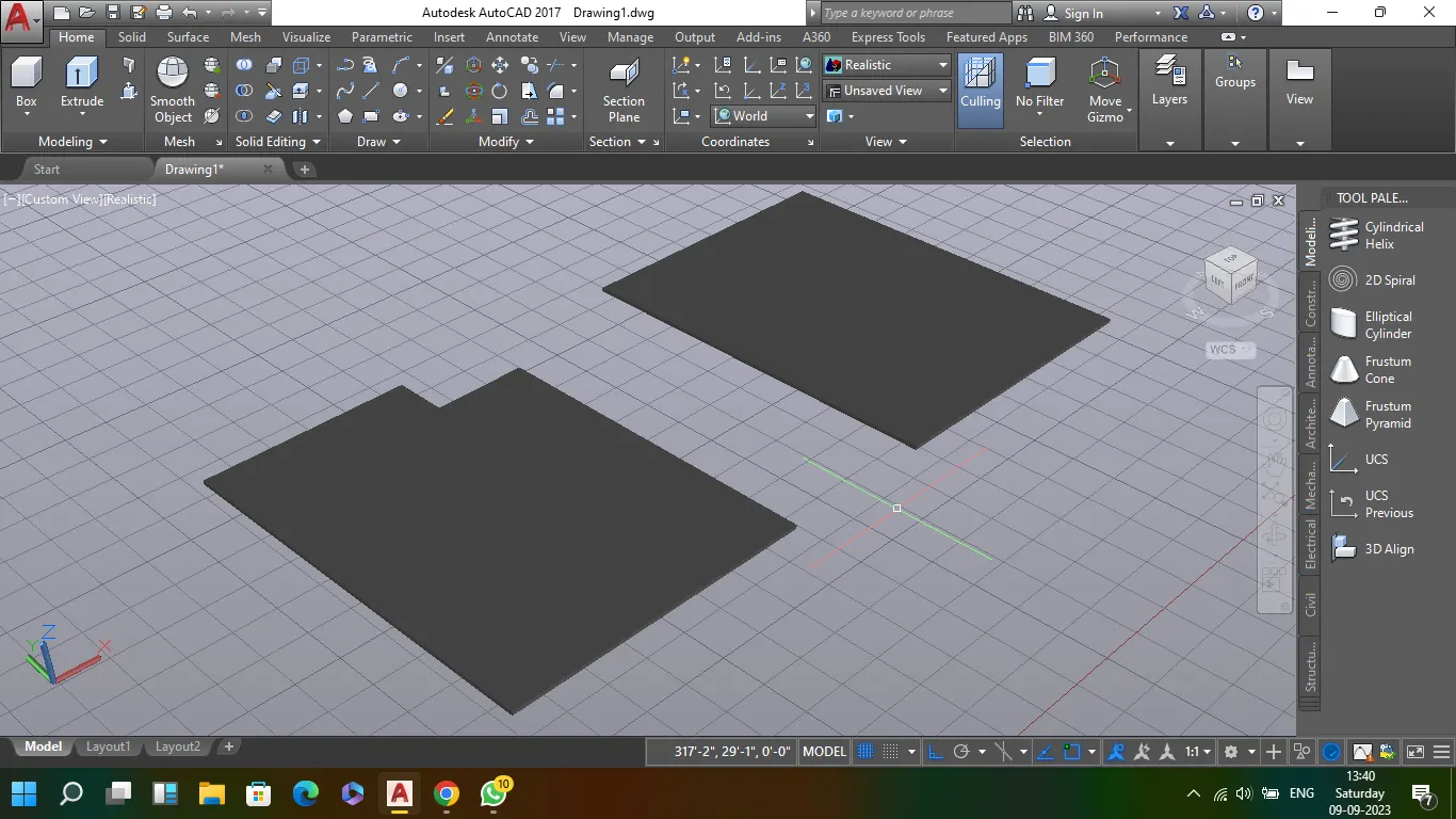
- draw the outer line of the 2D drawn building plan and region it using the boundary and assign it slab layer and extrude it for 6" to create the slab
- place the slab over the ground floor wall using move command and place the first floor wall model over slab and place the top slab over the first floor wall
- using UCS command change XY plane and draw the stairs using line command as 2d drawing and region it using boundary, using extrude command extrude the stairs into 3d stairs
- copy the 3D stairs and place it to each floors and draw the circle of 2" dia and line of 3' , using sweep command press on circle first and later on line , a gaurd railing is created and it is copied in to each stairs and using polyline draw the line connecting to each gaurd rail and using sweep command press on circle and to pline, so a railing is created
- to create the paraphet wall draw a line along the boundary of top slab, using polysolid command click on line, a paraphet wall is created and same thing is done to create the compound wall
- to create the gate draw the rectangle of required size and using circle draw the design and using extrude and substract command a design is made and place it in the gate space
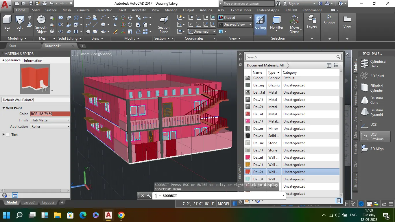
- now it comes to asign the material into the objects of buildings. Using the material command assing the wall paint to wall, alluminum metal to mullion, glass to glass of window, wood to door, stainless steel to railings and gate, metallic pain over gate, railings and window frame, ceramics on the floor and granite over the outer columns
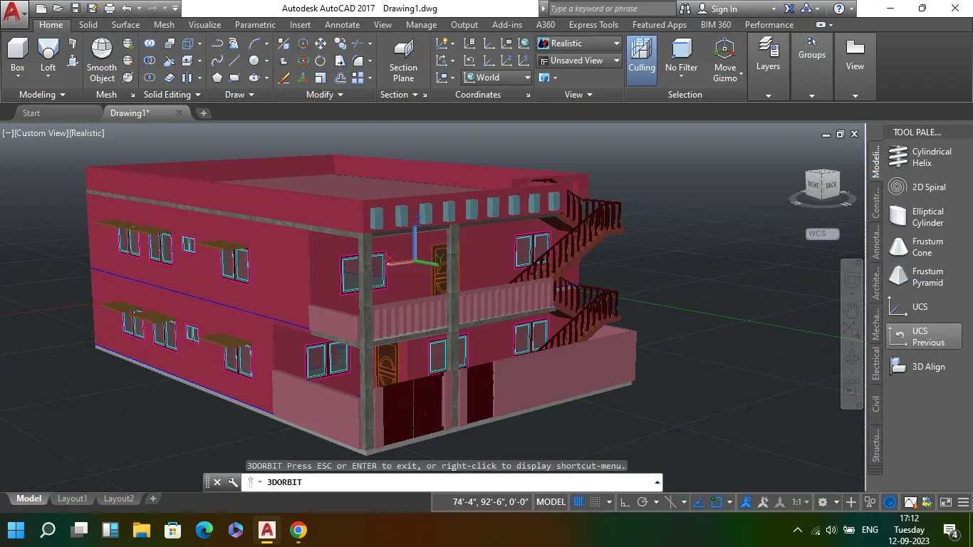
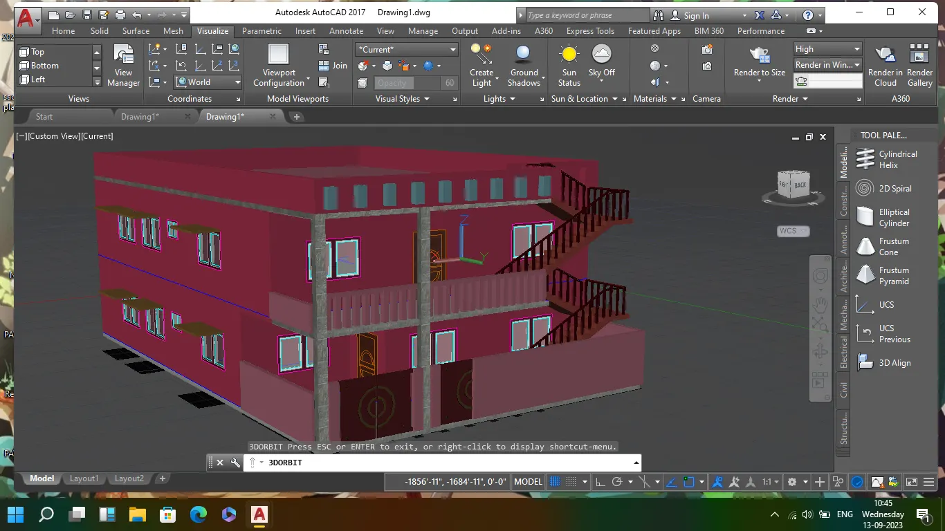
- after asigning all the materials into components, select the realistic view
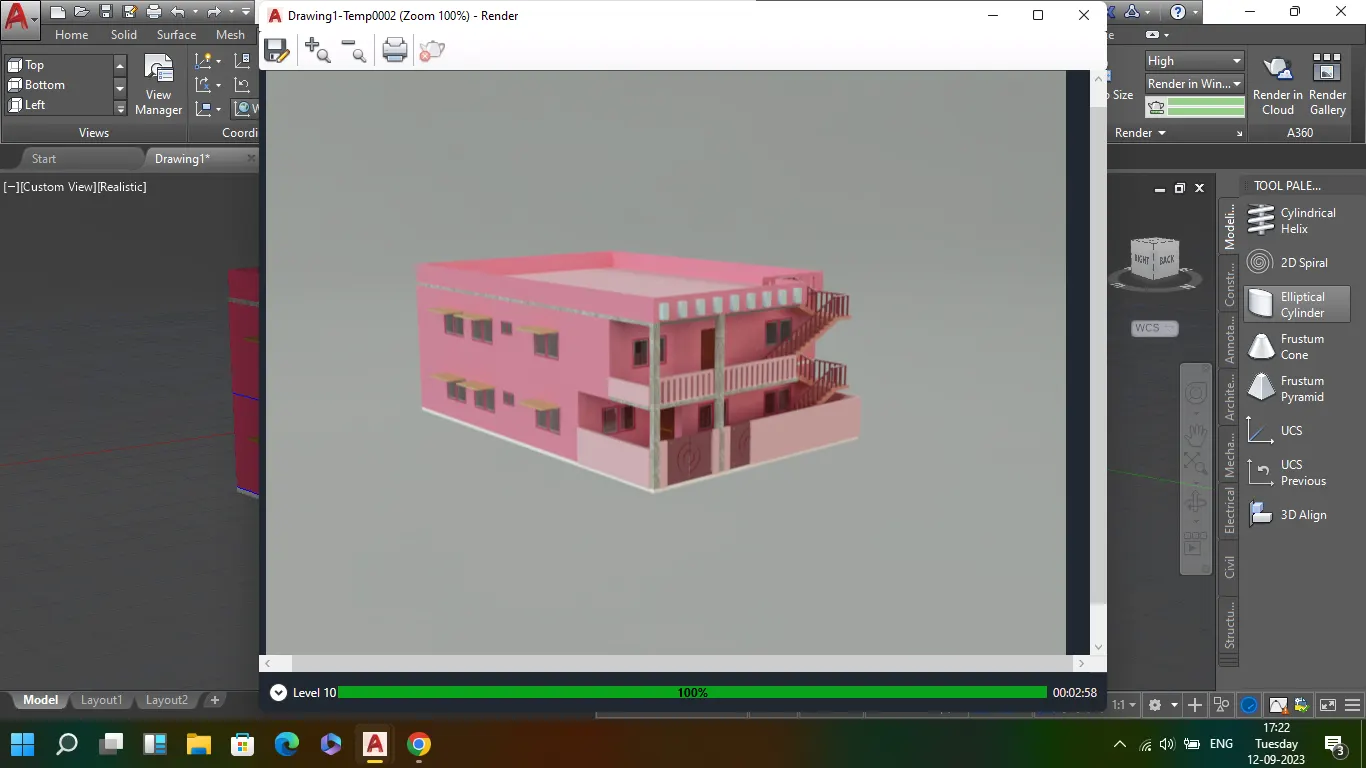
- place the lighs where its necessary and apply shadows and environmental factors where its necessary and render the whole model
result: