Project 2_Creating a 3D rendered model for a Residential Building in AutoCad
- PROJECT : Create a 3 dimensional model of the residential building with a rendered view.
- AIM:
- TO DRAW THE 3D RESIDENTIAL BUILDING AND TO CREATE THE RENDERED VIEW
- PROCEDURE :
- DIMENSION :
- EXTERNAL WALLS : 9"
- WINDOW : 3'X4'
- DOORS : 4'X7'
- ALL DIMENSION IN INCHES
- PROCEDURE :
- click on autocad software and start the application
- command : qnew
- click on advance setting
- unit : engineering precission 0'-0"
- angle : decimal degree presicion 0
- angle measure : EAST and click on NEXT
- angle direction : counterclockwise
- then provide requried area
- press : enter
- keep ortho on
- keep grid mode off
- press : enter
- command : UN (for units )
- unit : engineering precision 0'-0"
- scalce inches
- press : enter
- STEP BY STEP PROCEDURE :
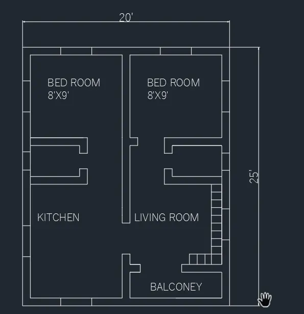
- DRAW A 2D FLOOR PLAN :
- command : REC (for rectangle )
- select the start point anywhere
- click on dimension
- length : 20'
- width : 25'
- press : enter
- command : O (for ofset )
- select the object
- give the ofset distance as 9"
- press : enter
- command : X (for expode )
- select the object
- press : enter
- command : o (for ofset )
- distance : 8;
- press : enter
- again ofset :
- distance 9"
- press : enter
- complete the whole plane by using ofset , line , and triam command
- press : enter
- then draw window and door by using ofset, line command
- command : DIMLIN (for dimension )
- give the dimension )
- press : enter
- command : MTEXT (for text )
- write the text as shown in plan
- press : enter
- go to the workspace
- select the 3d workplace
- visual style 2d wirwframe
- command : 3d orbit
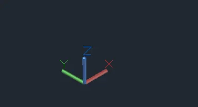
- command : UCS
- ucs direction as shown in fig
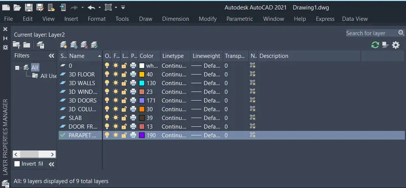
- then create a layers as shown in fig
- go to layers
- create a new layers
- click on top view
- command : REC (for rectangle )
- click anywhere for first point
- click on dimension
- length : 25'
- width :30'
- press : enter
- command : O (for ofset )
- distance : 9"
- press : enter
- commnd : EXT (For extude )
- select the object
- extude height 9"
- press : enter
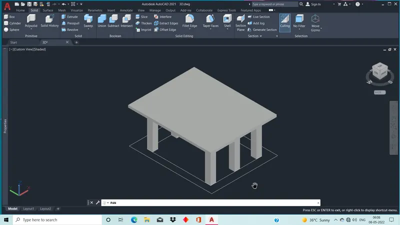
- command : REC (for rectangle )
- for column
- draw requried sizes of rectangle
- make it region
- command : EXT (FOR EXTUDE )
- Select the columns
- heigth : 7'
- press : enter
- command: REC (FOR RECTANGLE )
- select the first point
- click on dimension
- distance : 20'
- width :25'
- press : enter
- make it region
- command : EXT (for extude )
- height : 9"
- for floor as show below
- command : MOVE
- placed it properly
- press : enter
- command : COPY
- copy the floor plan
- select the base point
- and copy it
- command : 3dorbit
- command : UCS
- ucs direction shown below
- command : EXT (for extude )
- select the boundary
- extude height is 10'
- press : enter
- give the height of walls 10'
- then ,
- command : REC (for rectangle )
- for window
- select the boundary
- command : EXT (FOR extude )
- select the extude height is 3'
- press : enter
- command : copy
- put dynamic ucs on
- select the base rectangle
- put it at top of wall
- command :ext (for extude )
- select the object
- and extude it at requried height
- press : enter
- command : UNION
- select the solid surface
- press : enter
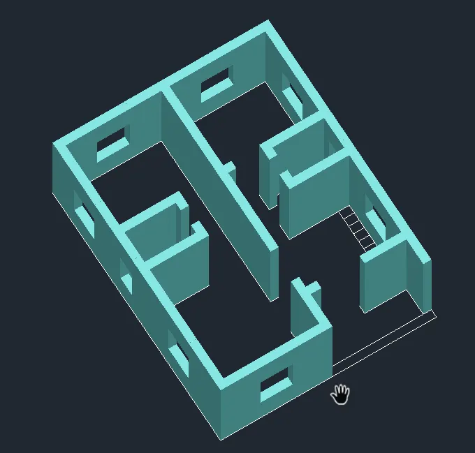
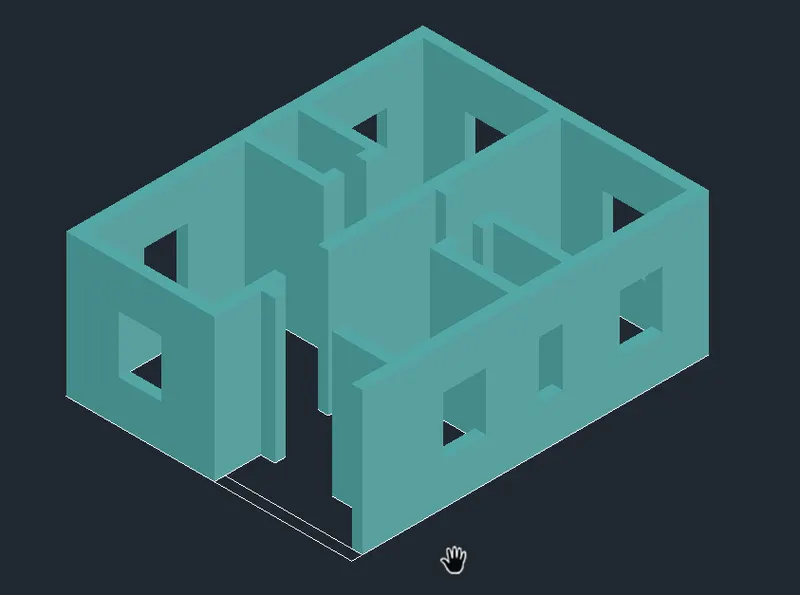
- go to the view
- create a new view
- as shown in fig
- VIEW 1 :
- VIEW 2:
- FOR DOORS AND WINDOW :
- command : UCS
- select the proper dimension
- command : REC (for rectangle )
- select the start point anywhere
- click on dimension
- length : 4'
- width : 7'
- press : enter
- command : x (for explode )
- select the object
- press : enter
- put object snap on
- command : L (for line )
- select the midpoint of top of window
- and divide the window in two parts
- command : REC (for rectange )
- give the start point
- and draw the rectangle
- command : copy
- click on multiple
- select the base point of rectangle
- and copy it
- command : MI (for mirror )
- select the all small rectangle
- and mirror it as shown in fig
- command : JOIN
- select all content
- press : enter
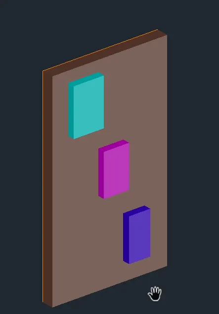
- command : EXT (FOR entude )
- slect the panal of door and extude it at -5"
- press enter
- command : presspull
- select the small rectangle
- give distance 2"
- press : enter
- door is ready
- in this way create a window
- by using move and ucs command placed all doors and window at proper postion
- command : COPY
- select the first floor
- and coppy it
- command : REC (for rectangle )
- draw the rectangle for slab of the first floor
- then command : O (ofset )
- distance : 9"
- press : enter
- command : PRESSPULL
- slect the rectangle
- and give 9" slab
- press : enter
- again coppy
- and give the 2nd and 3rd floor
- same way
- again command : REC (for parapet wall )
- draw the rectangle
- command : presspull
- give the height of parapet wall is 7'
- press : enter
- then draw the swimming pull
- command : L (FOR LINE )
- draw the stracture shown below
- command : F (for filete )
- click on RADIUS
- give the filite radius is 9"
- click on multiple and filite it
- command : JO (for join )
- slect the object
- press : enter
- command : O (for ofset )
- distance : 9"
- press enetr
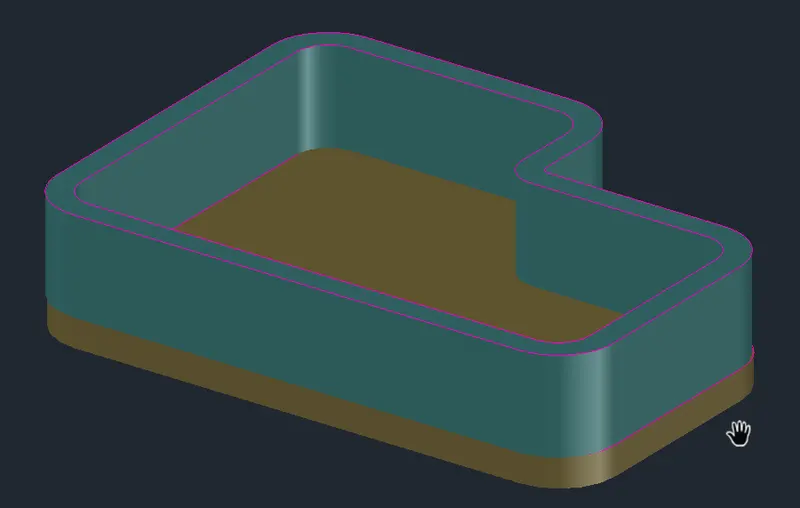
- coomand : PRESSPULL
- select the swimming pull object
- give the height is 3'6"
- press enter
- the object sown below
- then draw the upper room
- draw the rectangel as per recquriment
- command : o " ( for ofset )
- distance : 9"
- press : enter
- command : PRESSPULL
- select the wall
- give height as 7'
- press : enter
- commans peryamed
- for room
- draw it
- and place it properly by using move nd ucs command
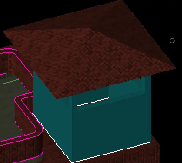
- commad : UNION
- select the solid surface
- make it union
- in this way 3D building ready
- command : MAT (for material )
- click on HOME
- then go to the autocad labrioury
- select the material
- like wood , stone , floor tile , glass , water etc
- appy all the material to the building
- press : enter
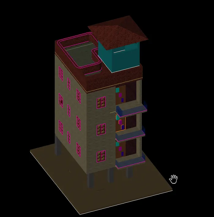
- command : CAMERA
- placed the camera at requried height and select the requried target
- create two camera view
- press : enter
- command : RR (FOr render )
- and give the rendering to the building