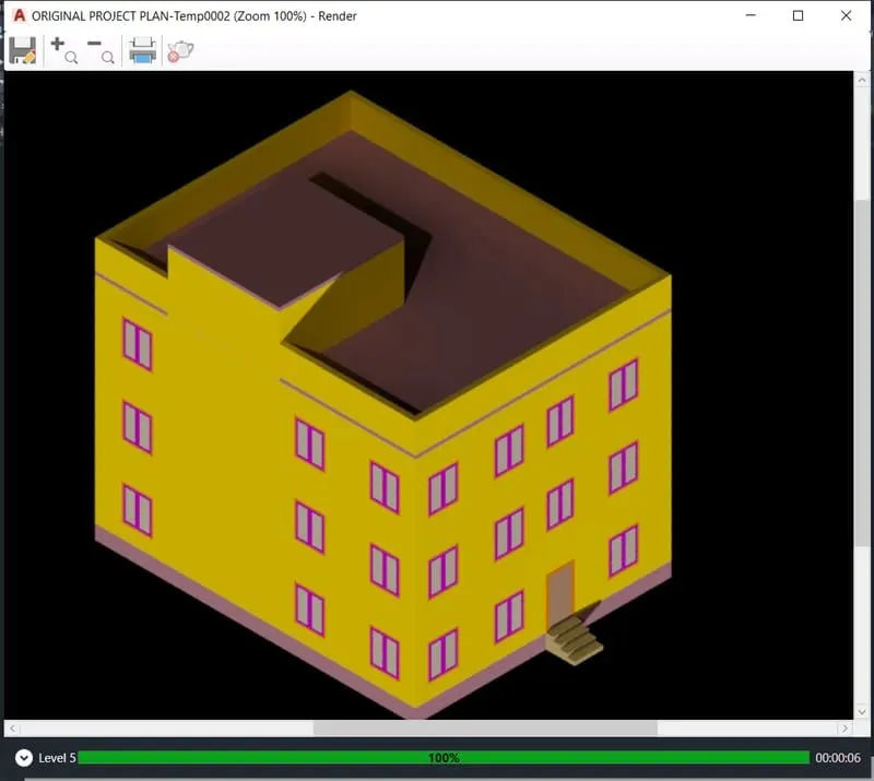
Project 2_Creating a 3D rendered model for a Residential Building in AutoCad
PROJECT 2
AIM:- Creating a 3D rendered model for a residential building in autocad.
INTRODUCTION:-
Command used for drawing the 3D rendered view of building are as follows.
Extrude - location: draw > modeling > extrude
This autocad 3D extrude command allows the user to create a 3D object by extruding a 2D face along a line or path.
Sweep - location: draw > modeling > sweep
This command helps the user to extrude the 2D objects without the 2D face being orthogonal to the beginning of the path.
Union - location: modify > solids editing > union
This autocad 3D command aloows the user to combine two objects converting into one single objects.
Subtract - location: modify > solids editing > substract
This command is opposite to the union command; this command works when there is a common area in both the objects. then this command subtract the objects A from the objects B.
Intersect - location: modify > solid editing > intersect
With this autocad 3D command the user is left with the area that is common to both the objects.
Revolve - location: draw > modeling > revolve
This autocad 3D command creates a 3D solids by revolving a 2D objects around as axis.
STEPS FOR CREATING A PLAN:-
* Open autocad
* In the right left corner click on the setting icon that is the icon of workspace.
* select 3D modelling.
* Enter UN (units) command in the command box and change the type as decimal and select precision as 0.0
* Now enter DIM style in command box and modify the setting and select primary units as decimal and give precision as 0.0
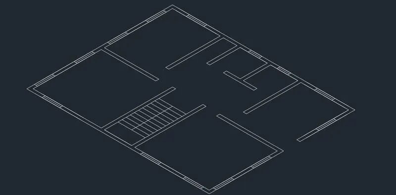
* select line command and draw in top or 2D mode.
* Line command is used to draw the plan.
* Command X line and draw line in X direction as well as in Y direction.
* Trim the unwanted corner lines.
* Offset 230 for wall.
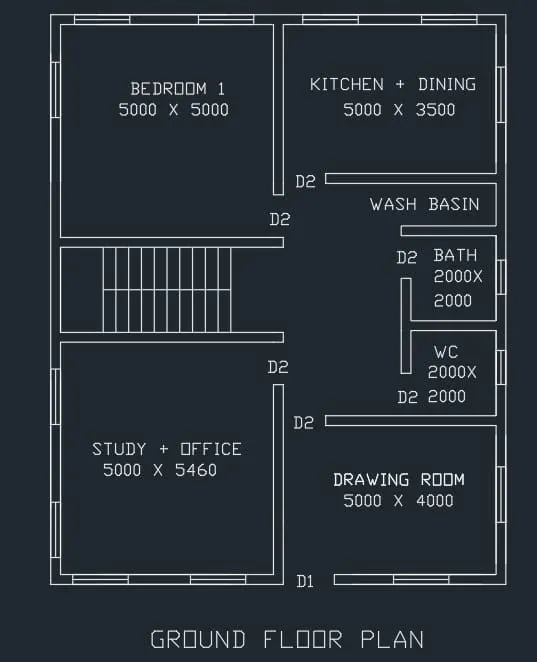
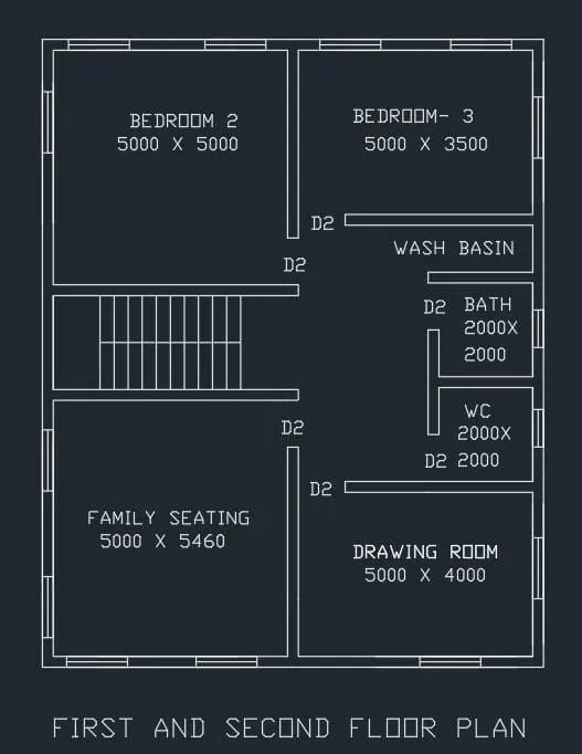
* Offset 5000 for bedroom in X direction and 5000 in Y direction
* Offset 230 for wall.
* Offset 5000 in X direction and offset 3500 in Y direction for kitchen + dinning.
* Offset 2000 in X and 2000 in Y direction both for bath and WC.
* All walls are 230 mm thick.
* Line command is used to draw windows and doors.
* Size of window is 1500 x 1500.
* Size of doors are 1000 x 2100 and 1200 x 2100.
* Landing width is 1000
* Tread is 300 and rise is 150.
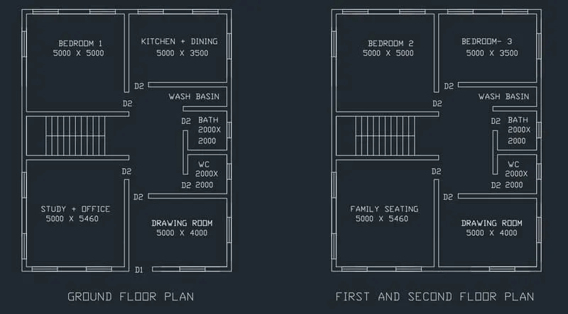
* Mtext command is used to give naming to the plan.
STEPS FOR CREATING THE 3D PLAN:-
* In the right left corner click on the setting icon that is the icon of workspace.
* Select 3D modelling.
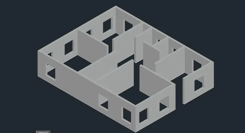
* Command boundary and in that select region.
* Create boundaries as well as regions of the plan.
* Extrude the regions that are the walls to the height of 3000 from bottom.
* Floor to floor height of the building is 3000.
* Create different type of layers using layer properties like 3D walls, window frames, slab, window glass etc as desired.
* Assign colors to each layers separately
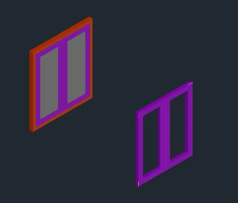
* Line command is used to draw the windows and doors.
* Extrude the windows and doors to the suitable depth.
* Rotated 3D is used to rotate the objects as in windows and doors.
* Move and copy command is used to move the windows to their desired location.
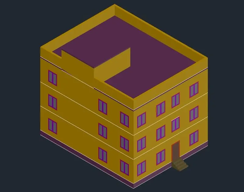
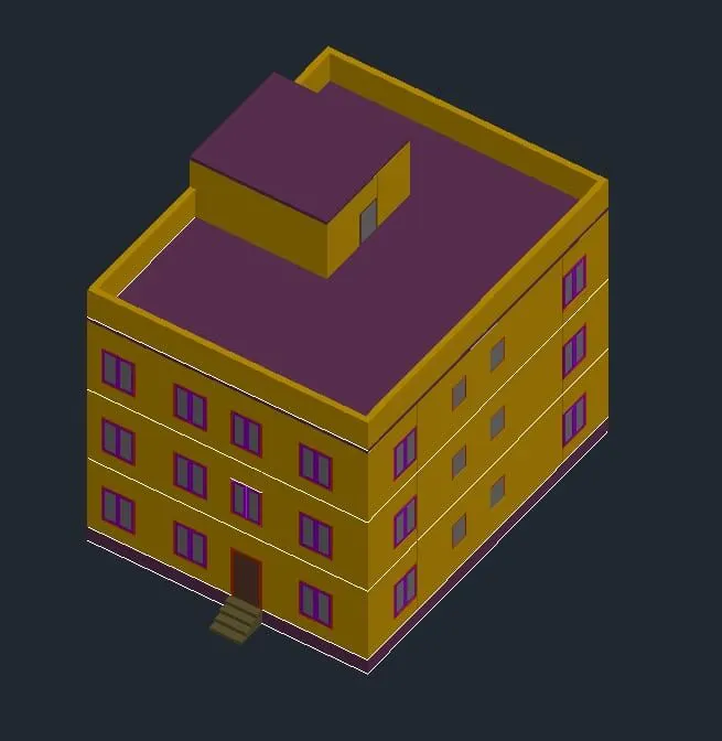
* Command polyline at the terrace and create the parapet wall at the top of the building.
* Command polyline and create the plinth of the building of 600 at the bottom.
* Create the staircase and extrude it to the distance of 1200.
* Create the mumty separately and place it on the top of the building.
STEPS FOR RENDERING:-
* Go to the visualize tab from the fibbon
* This will give access to the panels like light, sunlight, camera, animation, render and views.
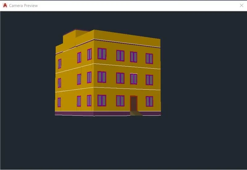
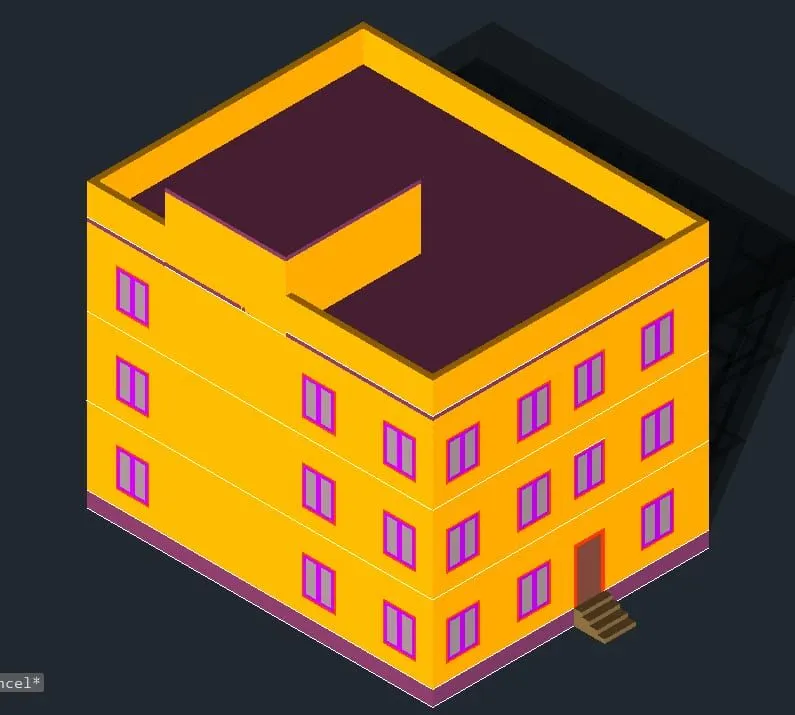
* Create different view using the camera anf render the building.
* Place the lights at the desired locations.
RENDERED VIEW:-