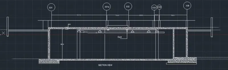
Creating Kitchen layout, Hatching of Architectural elements and sectional view of an Industrial Building in AutoCad
1)
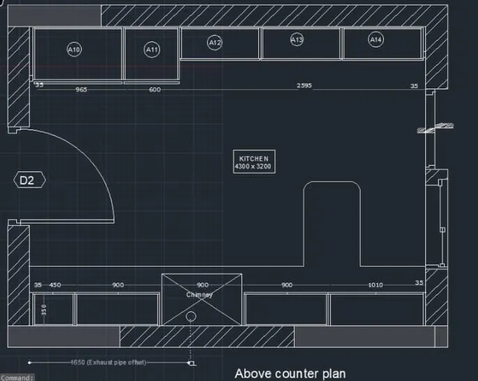
AIM: To create the kitchen layout and to also, use proper dimension technique to dimension the kitchen layput. also, insert text wherever required.
All dimension are in mm
PROCEDURE:
step1:
* units are set to mm
* limits and limax are also set
* zoom command is also used
steps for drawing below counter plan
* open autocad and enter UN (units command) in command box and make the type as decimal.
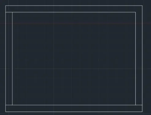
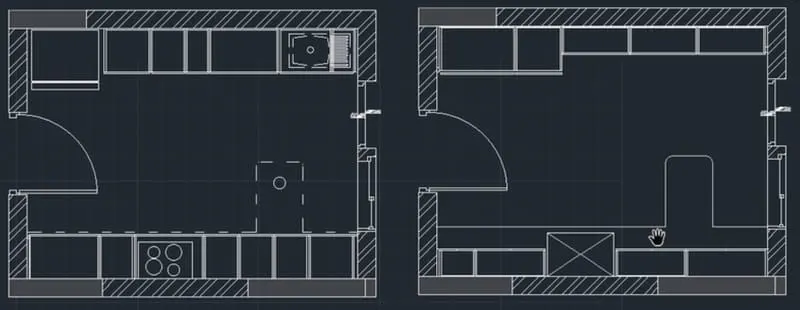
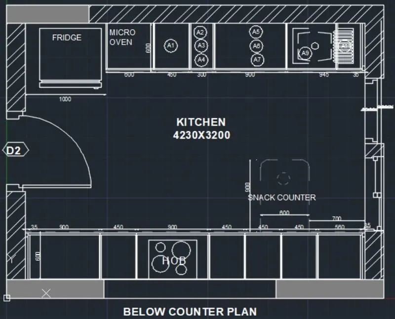
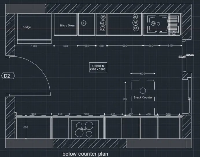
* select line command and draw a line of 4300 in X direction and a line of 3200 in Y direction and complete the rectangle.
* offset 230 towards all sides of the rectangle outside the figure.
* fillet all the offset edges.
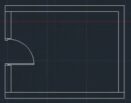
* offset of 600 from top of the room to draw the kitchen plateform and otta.
* give the offset as follows from left sides 90 as first offset - 90 mm as first offset, 1000mm for fridge, 600 for micro- oven, 450 for A1 part, 300 for A2/A3/A4, 900 for A5/A6/A7, and 300, 945 and 35 offsets.
* offset 12mm to both sides in each corner of the room.
* offset 600mm from bottom in middle of kitchen to draw platfrom.
* now enter offset as follows- 900, 450, 900, 450, 450, 450, 560, 35.
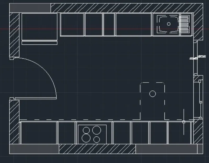
steps for drawing above counter plan
* open autocad and enter UN (units command) in command box and make the type as decimal.
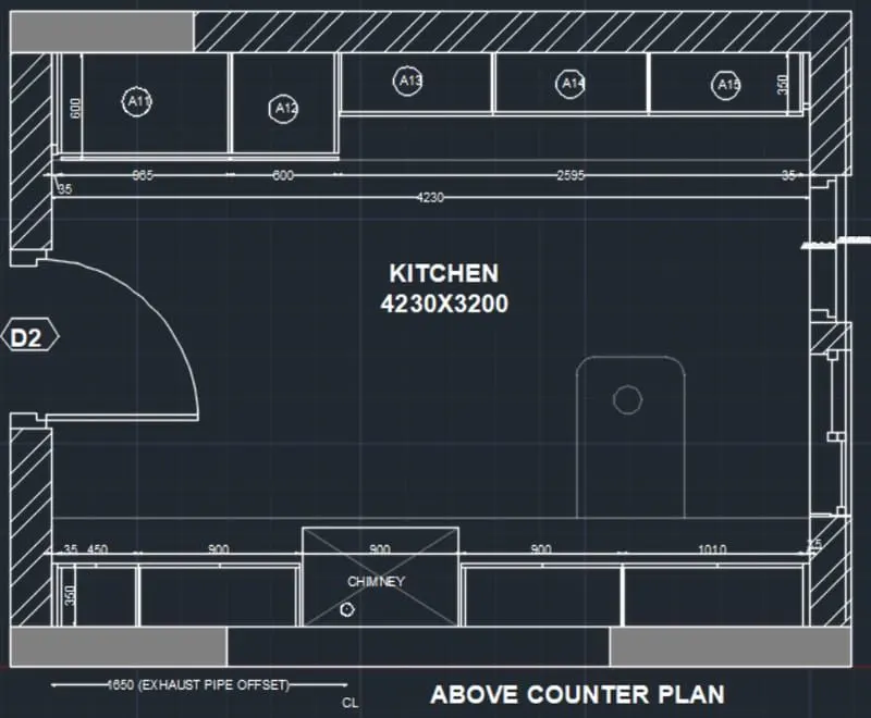
* select line command and draw a line of 4300 in X direction and a line of 3200 in Y direction and complete the rectangle.
* offset 230 towards all sides of the rectangle outside the figure.
* fillet all the offset edges.
* offset of 600 from top of the room to draw the kitchen platfrom ink and otta.
* give the offset as follows from left sides 35 as first offset and again the offset as 965, 600, 2595.
* offset 12 mm to both sides in each corner of the room.
* offset 350 mm from bottom in middle of kitchen to draw platfrom.
* now enter offset as follows- 35, 450, 900, 900, 900, 1010, 35.
HATCHING OF OBJECT:
* click home tab- draw panel- hatch.
* on the properties panel hatch type list, select the type of hatch that you want to use.
* on the pattern panel, click a hatch pattern to fill.
* on the boundaries panel, specify the how the pattern boundary is selected.
* pick point inserts the hatch or fill within a closed area that is bounded by one or more objects.
* select boundary objects. inserts the hatch or fill within a closed object.
* the selection method is retained until you change it.
* click an area or object to be hatched.
* on the ribbon, make any adjustments as needed.
* on the properties panel, you can change the hatch type and colors or modify the transparency level, angle, or scale for the hatch.
* on the expanded option panel, you can change the draw order to specify whether the hatch and its boundary are displayed in front of or behind other objects.
* press enter to apply the hatch and exit the command.
* hatch the brick wall with hatch typ as ANS132 and hatch other part as solid and grey colour.
RESULT:
2)
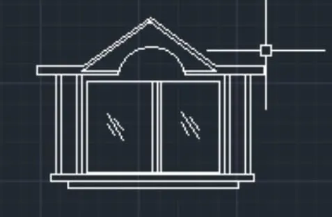
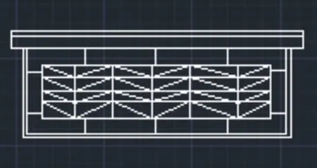
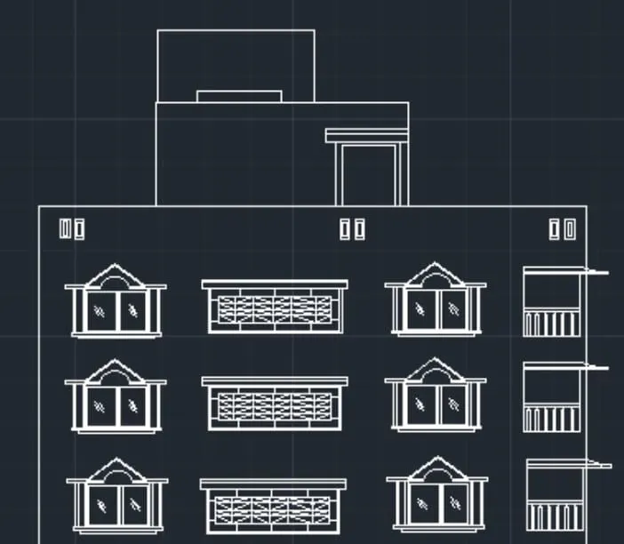
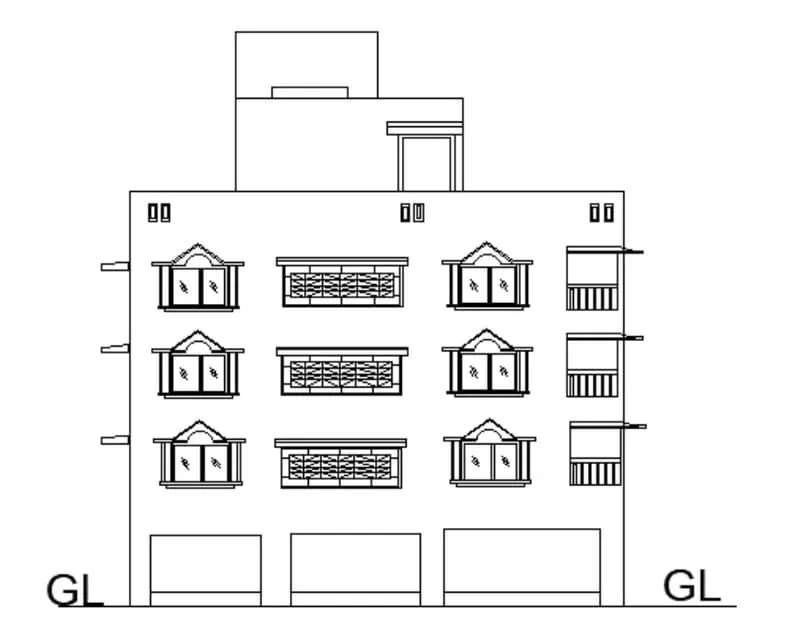
AIM: To create elevation and hatching the structural and non-structural elements of the building like walls, columns etc.
PROCEDURE
steps for drawing section
* select line command and extend the lines from the plan in the downward manner to create projections.
* offset 150mm from the ground level.
* offset 2450 for ground floor.
* offset 2850 for second floor.
* offset 2850 for third floor.
* offset 1000 for parapet wall.
* offset 2500 from terrace level for mumty.
* offset 450 from mumty for parapet wall of mumty.
* offset 600 and offset 1200 for O.T.H.
* for drawing of staircase offset 1250 for tread and offset 143.75 for rse of staircase
* offset 125 below floor level for slab.
* draw the chajjas and windows as per the sizes considered and standards.
* draw the railing of staircase in dash manner from the layers and change the layers toACADIS003W100.
* give the dimension by dim linear or dim continue command.
* select the multiline text for naming of the section.
HATCHING OF OBJECT
* click home tab- draw panel-hatch.
* on the properties panel hatch type list, select the type of hatch that you want to use.
* on the pattern panel, click a hatch pattern or fill.
* on the boundaries panel, specify the how the pattern boundary is selected.
* pick points. insert the hatch or fill within a closed area that is bounded by one or more objects.
* select boundary objects. insert the hatch or fill within closed object.
* the selection method is retained until you change it.
* click an area or objet to be hatched.
* on the ribbon, make any adjustments as needed.
* on the properties panel. you can change the hatch type and colors or modify the transparency level, angle, or scale for the hatch.
* on the expanded option panel. you can cange the draw order to specify whether the hatch and its boundary are displayed in front behind other objects.
* press enter to apply the hatch and exit the command.
* hatch the brick wall with hatch type as brick and hatch other part of concrete as air conc.
RESULT:
3)
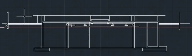
AIM: To create the section view of an industrial building.
PROCEDURE:
* in the command prompt type l to draw the lies.
* in the ribbon bar > hatch < ar.conc.
* in the command prompt type rec to draw the rectangle.
* in the command prompt type LT to get the dotted line
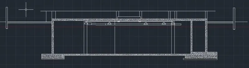
* in the the command prompt type MT to draft the text
* in the command prompt type c to draw the circle
* in the command prompt type dim to draft the dimensions
RESULT: