Project 2_Creating a 3D rendered model for a Residential Building in AutoCad
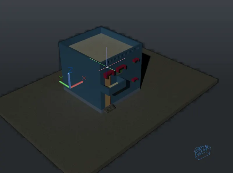
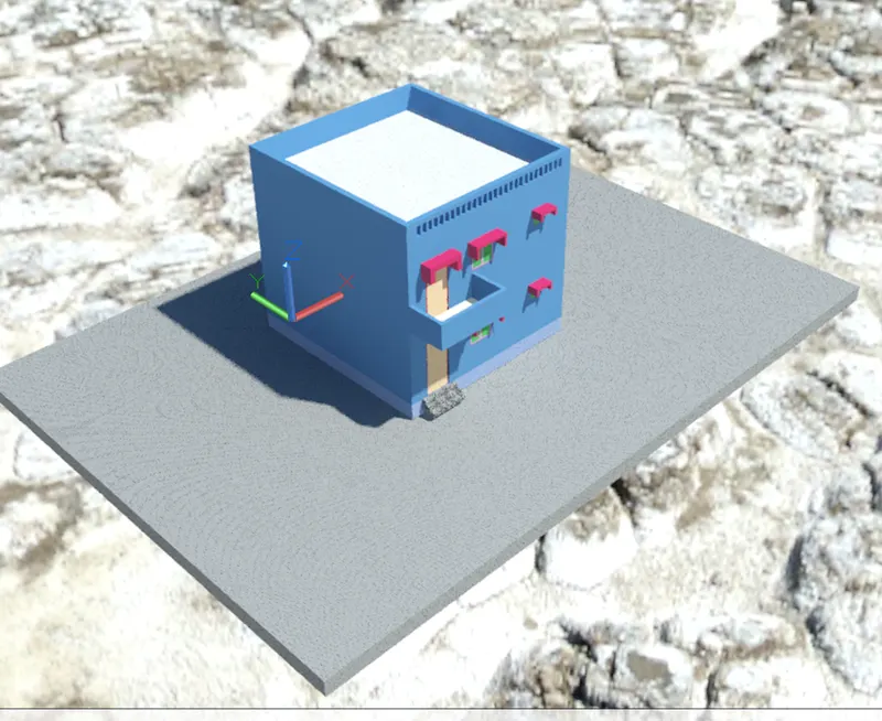
Aim: to draw the 3-dimensional model of a residential building with rendered view.
Procedure: Open Auto CAD and set the limits. set the units to metric as the plot is in meters.
- Architectural drawing
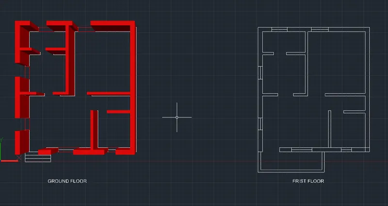
- a) Plan:
- Give the size of the plot using the rectangle command and offset for the thickness of the wall.
- Give the orientation of the plot by marking the east direction.
- Now we draw the ground floor plan.
- Using offset command draw the bedroom of size 8X7.65m.
- Then for the hall offset 4.5m in vertical direction and 4.65m in horizontal direction.
- For the bed room offset 3m in vertical direction and 4.65m in horizontal direction.
- For the toilet offset 3m in vertical direction and 2.5m in horizontal direction.
- For kitchen offset 4.5m in vertical direction and 2.5m in horizontal direction.
- Now draw the stairs 1.5m for the offset of the width of stair.
- Now we draw the first- floor plan:
- Copy the ground floor plan and we make few changes.
- Draw balcony outside the first- floor hall
- Now we create the doors and windows and making them as block.
- Assume door sizes as: D1 -1X2.15m and D2-0.90X2.15
- Place the doors wherever opening is provided and mark them as D1 or D2 wherever required.
- Assume the size of windows as- 1.2x1.5m and ventilator as-0.6X0.60m.
- Place the windows and ventilators in the required place.
- Mark them as W and make them in a block.
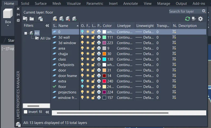
- Now create the layers using layer properties.
- Assign different colours to each layer in order to distinguish it.
- Insert respective elements in the layer.
- b) Elevation:
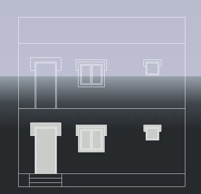
- Now project the lines to draw the elevation.
- Project the wall line to the top and draw a horizontal line.
- Offset 0.60m for the plinth level and 3m for the first floor level and 3m again for second floor.
- We draw the doors and windows from the plan and give height of 2m and 1m as required.
- Project the shades and draw the shades at top of window level.
- Trim off the extra lines using trim command.
- Copy the windows and doors to other side also and draw the sunshade also.
- Project 1m to top to show the parapet wall.
Layer properties:
3D modelling
- Make sure workspace setting is 3D modelling from status bar.
- Select the SW view from viewport control.
- Type BO in command box, press enter, pick the internal point inside the wall thickness of plan to create it as boundary.
- Type EXTRUDE in command box, press enter, select the created boundary, specify height of extrusion as 3000 units and press enter.
- To create the sill level for window opening, type BO in command box, press enter, pick the internal point inside the wall to create it as boundary.
- Type EXTRUDE in command box, press enter, select the window plan and specify extrusion height as 1000 units and press enter.
- Type REC in command box, press enter, specify first point at corner of top of window opening and draw the rectangle at top of window opening.
- Type EXTRUDE in command box, press enter in command box, select the drawn rectangle and specify extrusion height as -850 units and press enter.
- Similarly create the top of door opening.
- Type UNION in command box, press enter, select the all created objects and create them as single unit.
- Similarly draw the first floor as shown below.
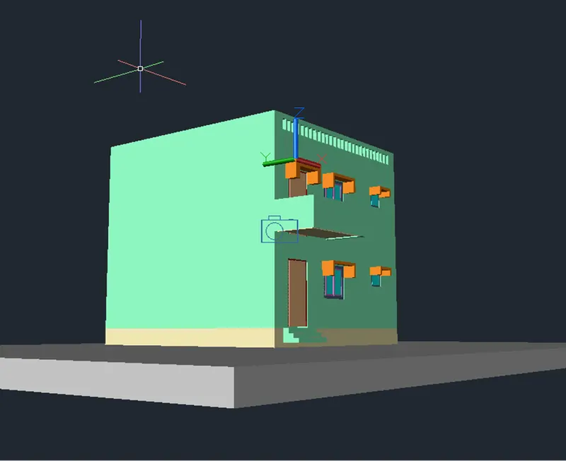
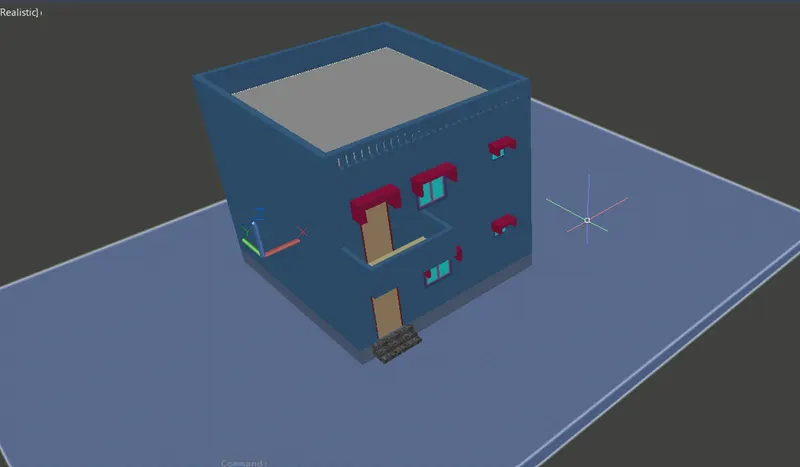
- From the material panel of visualization tab select the material browser and select the flooring type as diamond Red, add it to the list, select the flooring, right click on the diamond red option from list and select assign to selection option to apply flooring material.
- Select the material mapping from the material panel of visualization tab and adjust the applied material.
- Similarly apply the material to various components of building by similar procedure.
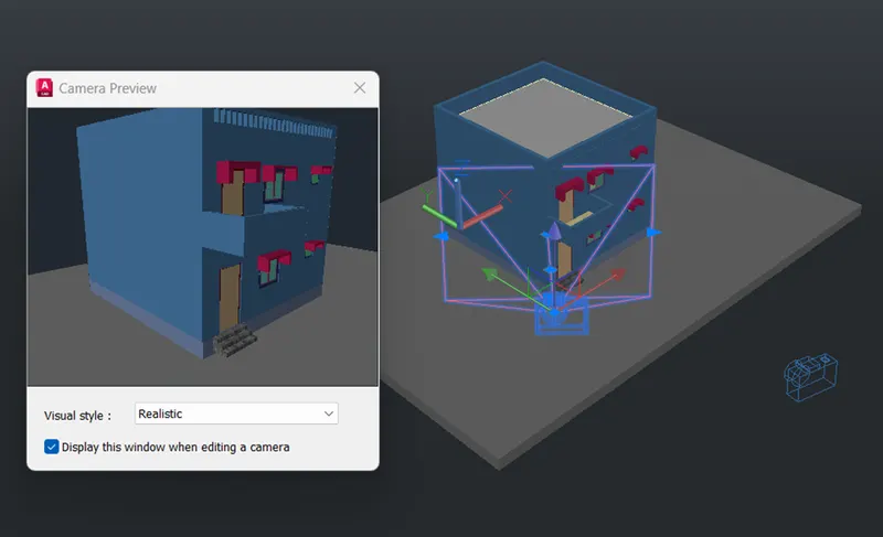
- From camera panel of visualize tab select create camera option and create the camera at certain height as shown below.
- Double click on camera, to see the camera view.
- Select camera and right click to change the properties of camera as shown below.
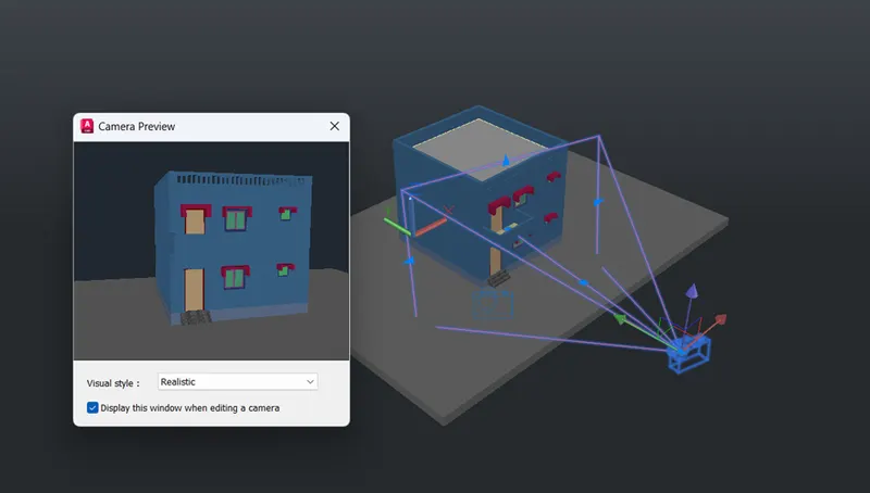
- From the visualize tab, from light panel select the full shadow option.
- Type BACKGROUND in command box, press enter, select the background type as sun and sky and select ok.
- From the render panel of visualize tab, select the drop down of render panel and select the environment and exposure option, turn it on and select image-based lightning as dry lake bed.
- From the render panel of visualize tab select the render in region option.
- Type RR in command box, press enter, pick the crop window to create the render.
- Similarly, create the different rendered view of building.
- Select the render window option from the render drop down of render panel of visualize tab and save the view by selecting render in window option and save it.
Result:
A 3-dimensional model of the residential building with a rendered view is created using AutoCAD software as shown below.