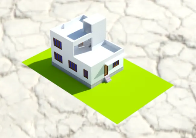
Project 2_Creating a 3D rendered model for a Residential Building in AutoCad
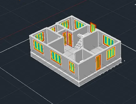
Create a 3 dimensional model of the residential building with a rendered view.
AIM: Project 2 - Creating a 3D rendered model for a Residential Building in AutoCad from auto cad 2D plan:
Introduction: create a 3D rendered model in auto cad 3D modelling using auto cad 2022 using 3D drafting commands like extrude,solid commands:
Procedure:
Step 1) make a 2D plan:
Open the autocad with (drafting and anotation).
Then go for decimal unit (meters)
Then draw a basic residencial plan.
Having external wall thickness are 9" and internal wall thickness are 9".
Using LINE command and REC command .
Also draw the window and ventillation with pannel.
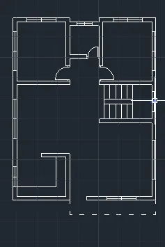
Step2:- Annotation to plan
The size of doors and window as:
D = 8'8" X 3'6"
D1 = 7'8" X 3'
D2 = 7'8" X 2'6"
W1 = 8' X 6'
W2 = 6' X 6'
W3= 4' X 6'
V = 3' X 3'
then Dimension the plan using DIM command.
Step3: First floor plan, ground floor.
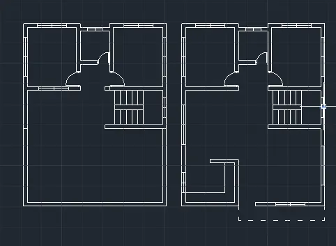
Step 4: Go for 3D modellineg
Then workspace switching in 3D modelling,
then go for view and make new view with 1 name
and go for iso view and make new view as 2
then union the all walls by using UNION command
and extrude the walls at height of 10' height
using EXTRUDE command .
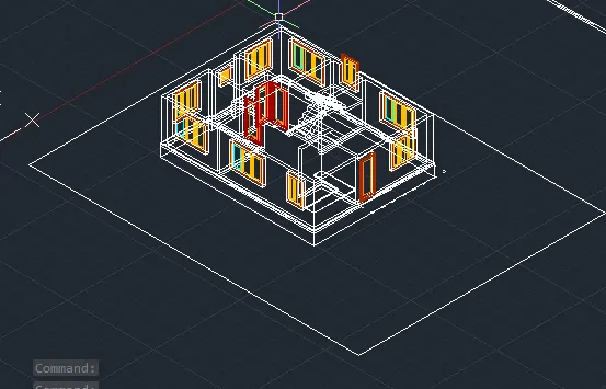
Step 5: Layers.
Go to layer manager and add the layers
for doors, windows and walls etc.
Step 6: Making window and door opening.
By using extrude command we use a window opening and door opening.
from bottom
and making for top cover with help of rectangle.
we draw rec at top side and extrude it at bottom
upto requird opening
and by using SUBTRACT command we will be subtract openings from walls.
Step 7: Makes door and window frames.
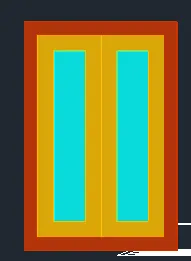
Draw a elavation of doors and window at outside ,
and draw the frame on it ,
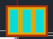
suppose we make window
first draw a external frame by drawing rectangle of window size at outside and by offseting it we make thick ,
and using extrude command we extrude watever we want.
same do for internal frame and panel also
and move the frame and panel inside .
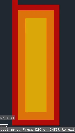
same make for ventilator
external frame, frame and panel
and move the frame inner
and move the glass panel
same do for doors
move the frame and panel to inner side for making projections
and apply for all doors
Step 8: Plinth
Set ucs at below the plan
and draw a rectangle with bottom of plan
and extrude it for 3' as plinth height .

Step9: Roof/slab.
Making a slab on that house
Set ucs at top and draw a rectangle by selecting layer as slab
and draw rectangle using rectangle command
and extrude it by 6" as slab thickness
Step 10: For first floor
Its easy for sel;ection so frozen the plinth layer from layer manager
and copy the section by selection whole and taking a base point
we got first floor for it .
Step 11: Making parapet walls.
draw a parapete wall from slab level
so using EXTRUDE command or presspul command
extrude the wall at parapet height
step12: Cladding to plinth.
For better appreance draw cladding plinth wall
draw rectangle of linth size
and draw a profile on that rectangle with 0.6 as plinth height
over periferi of plinth using extrude command
and then copy it and paste at plinth
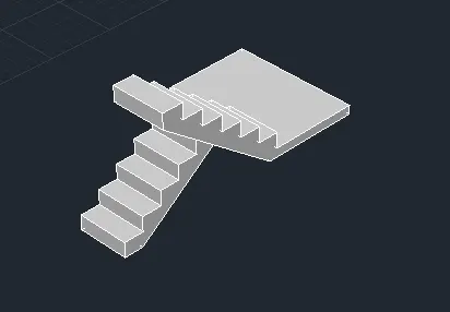
Step 13: Stairs.
Draw a stair using line command
Step 14: Making base for plan.
Go for world UCS.
and go to top draw a rectangle over the object
and then extrude it by some thickness
then move it by 2" below because base are required below pilinth.
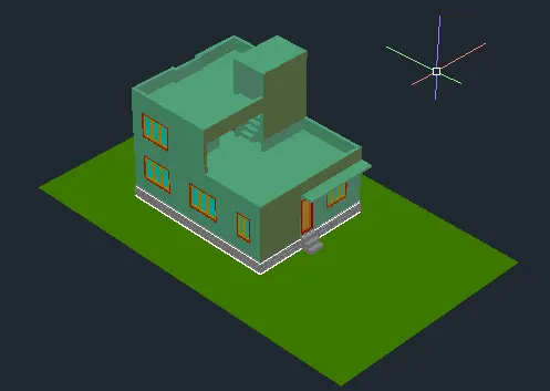
Step 15: Material.
Then go for material browser from annotation bar.
and assign diffrent material for difrent units .
by using setuv for material manager
select a category of material then select material from list
and the select object and assaign material to object.
Step 16: Sun
go for sun status
and keep it exposure
and make shaddow as full shadow
Step 17: Light
Go for create light from visualize.
select distance light
and set turn for default light
then give location of light
and set focus direction of light
name it as by light1.
Step 19: Environment setup.
from rendering option set enviornment setup
and select dry lake bed and set it.
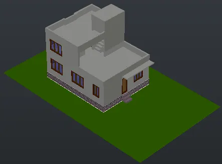
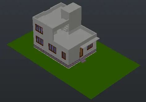
Step 20: Render setup.
go for rendering
select window
then select size of window
we can also change or setup the render from render setup
Step 21: Render
Finally go for rendering from render option
or RR command
Finally selecting the render option coffee break and rendering the view
Result : We rendered the 3d drawing of residential building using render command in AutoCAD 3d modelling