Project 2_Creating a 3D rendered model for a Residential Building in AutoCad
Project 2_Creating a 3D rendered model for a Residential Building in AutoCAD
*********************************************************************
PROJECT- 2
AIM OF THE PROJECT:
Creating a 3D rendered model for a Residential Building in AutoCAD.
INTRODUCTION- COMMANDS USED FOR DRAWING THE 3D RENDERED VIEW OF BUILDING ARE AS FOLLOWS.
- Extrude- Location: Draw > Modeling > Extrude
This AutoCAD 3D Extrude command allows the user to create a 3D object by extruding a 2D face along a line or path.
- Sweep- Location: Draw > Modeling > Sweep
This command helps the user to extrude the 2D objects without the 2D face being orthogonal to the beginning of the path.
- Union- Location: Modify > Solids Editing > Union
This AutoCAD 3D command allows the user to combine two objects converting into one single object.
- Subtract- Location: Modify > Solids Editing > Subtract
This command is opposite to the union command; this command works when there is a common area in both the objects. Then this command subtracts the object A from the object B.
- Intersect- Location: Modify > Solid Editing > Intersect
With this AutoCAD 3D command, the user is left with the area that is common to both the objects.
- Revolve- Location: Draw > Modeling > Revolve
This AutoCAD 3D command creates a 3D solid by revolving a 2D object around an axis.
STEPS FOR CREATING A PLAN-
- Open Auto Cad.
- In the right left corner click on the settings icon that is the icon of workspace.
- Select 3d modelling.
- Enter UN (Units) command in the command box and change the type as Engineer and select precision as 0’.”0
- Now enter Dim style in command box and modify the settings and select primary units as decimal and give precision as 0’.00”
- Select line command and draw in top or 2D mode.
- Line command is used to draw the plan.
- Command X line and draw line in X Direction as well as in Y direction.
- The whole dimension is in feet and inches
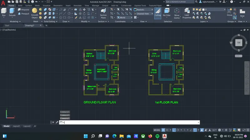
GROUND FLOOR
- Courtyard of 18’3”X19’6”
- Dining of 12’X12’
- Toilet {2}8’X7’
- Living room 17’ X 15’
- Bedroom 1: 12’X15’
- Bedroom 2 :17’X15’
- Kitchen 11’9” X 15’
- A staircase to the connection of ground floor to first floor
- Trim the unwanted corner lines.
- Mtext command is used to give naming to the plan.
First floor plan
- Gym 11’9” X 15’
- Dining 12’X12’
- Toilet {2} 8’X7’
- Bedroom 1 12’X15’
- Bedroom 2 17’X15’
- Wall thickness 8”
STEPS FOR CREATING THE 3D PLAN.
- In the right left corner click on the settings icon that is the icon of workspace.
- Select 3d modelling.
- Command boundary and in that select region.
- Create boundaries as well as regions of the plan.
- Create different type of layers using layer properties like 3D walls, window frames, slab, window glass etc. as desired.
- Assign colors to each layer separately
- Line command is used to draw the windows and doors.
- Extrude the windows and doors to the suitable depth.
- Rotated 3D is used to rotate the objects as in windows and doors.
- Move and copy command is used to move the windows to their desired locations.
- Command polyline at the terrace and create the parapet wall at the top of the building.
- Create the mumty separately and place it on the top of the building.
Plint area
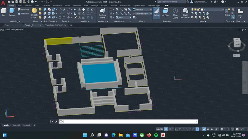
- Plint height of 36cm (about 1.18 ft) to all buildup area
Ground floor
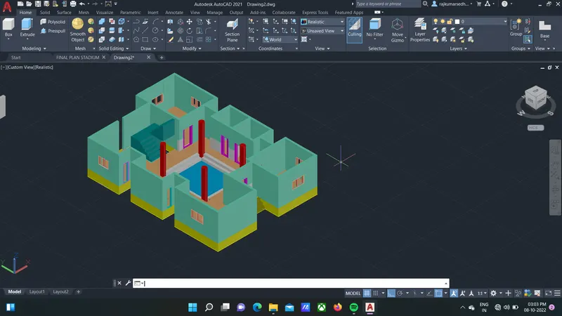
- Groundfloor height of 138cm (about 4.53 ft) full height from the plinth high
- With the windows 1, windows 2
- With the door D1, D2
- Four numbers of pillars in wooden in the corner of courtyard
- Staircases are being provide for the FirstFloor
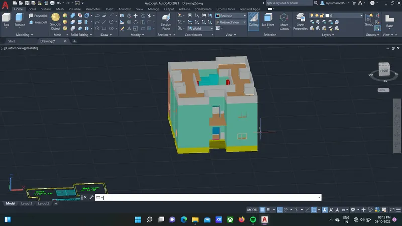
RESULT OF THE RESIDENTIAL BUILDING (COURTYARD)
------------------------------------------------------------------------------------------------------------------------------------------