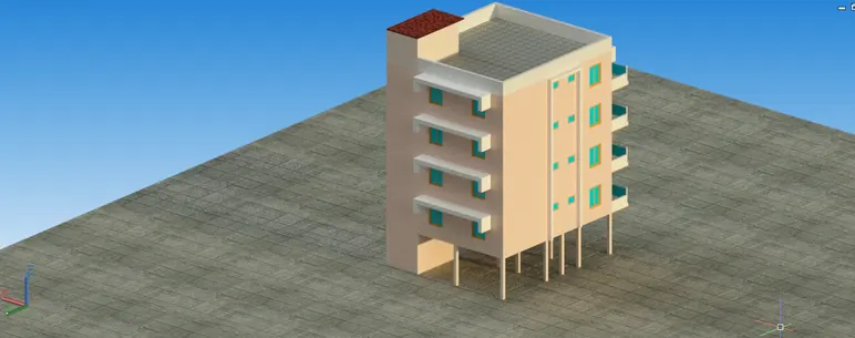
Project 2_Creating a 3D rendered model for a Residential Building in AutoCad
Aim :- To draw the 3D residential building and to create the rendered view
Introduction :-
The general commands used for drawing the building is as follows :
Line
Polygon
Rectangle
Circle
Erase
Copy
Trim
Offset
Extend
Move
Rotate
Dimension
Text
Fillet
Extrude
3D Rotate
Etc.
The dimensions:
External and Internal wall – 230mm thick
For Staircase : - Treads : 250 mm, Rise : 165mm
W – 1200 X 1500
V – 700 X 500
D1 – 1000 X 2000
D2 – 900 X 2000
All the dimensions are in mm
Procedure :-
Click on AutoCAD application and open this application
Type QNEW in command bar and enter
Select default setting as Metric
In default setting click on use a wizard and in that advance setting and set unit as decimal and precision as 0 and press Next
Set Angle as Decimal Degree and precision as 0 and click next
Set Angle Measure as EAST and press NEXT
Set Angle Direction as Counter-Clockwise and press NEXT
Set Area by providing Length as 50m and Width as 50m
Press finish
Keep ortho, Object snap >ON
Keep Snap and Grid > Off
Un+enter
Type > Decimal, Precision > 0
Units to scale inserted content > milimeter
Enter
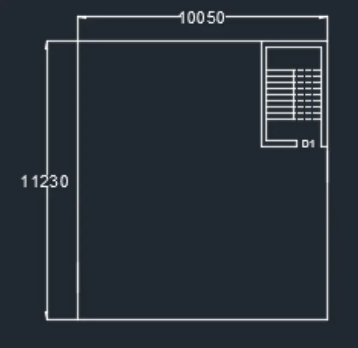
Steps to draw the Plan
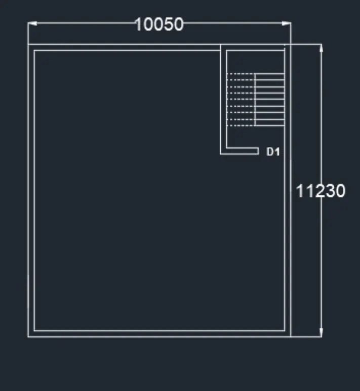
Take the line command
Specify first point > click anywhere on the sheet
Specify next point > type 10050 > Enter by keeping curser rightside
Specify next point > type 11230 > Enter by keeping curser upside
Specify next point > type 10050 > Enter by keeping curser Lefttside
Specify next point > type 11230 > Enter by keeping curser downside
Enter
Take the offset command
Specify distance > 230
Select object > Right side vertical line
Specify distance > 2460
Select object > Right side vertical line
Specify distance > 2690
Select object > Right side vertical line
Specify distance > 230
Select object > Top side Horizontal line
Specify distance > 4000
Select object > Top side Horizontal line
Specify distance > 4230
Select object > Top side Horizontal line
The stair case hall is ready
Take offset command
Specify offset distance > 900 to show landing width
Select object > Top horizontal
Specify Offset distance > 250 to show the tread
Select object > Landing line
Continuously provide the offsets for tread as per design requirement
By using line command divide the staircase tread in two parts to show the different flights
The ground floor plan is ready
Take copy command
Select the whole ground floor plan to prepare the First and Secon Floor Plan
By Keeping ORTHO mode On, Copy the entire drawing beside it
Take offset command
Specify offset distance > 230
Click on all the lines on the screen > Keeping curser inside the lines to show the wall thickness
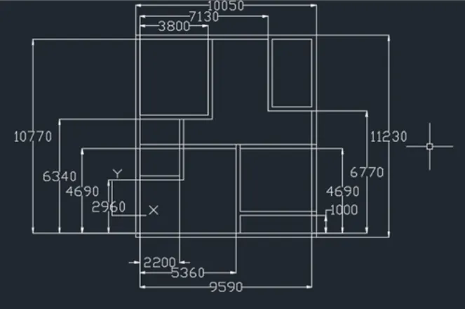
Take the offset command and provide the offset as per shown below
Also give offset to all the last offsets of distance 230 to show the wall thickness
Trim and erase the unwanted lines
Left the space for doors as per requirement
Use the line command to provide the windows
Use the copy and rotate command to provide the windows
Take a line and offset command to prepare the whole plan
Trim and erase the unwanted lines
Use the dash line to provide the chajja
Take the rectangle command
Specify first corner point > Anywhere in the drawing
Click > Dimension
Specify length > 230
Specify width > 230
Enter
Copy this rectangle to show the columns
To create the text
Click on Annotation tab >multi line
Manage textile > New
Style name as > Project > OK
Font Name > Arial
Height > 300
And press set current
Use multiline text
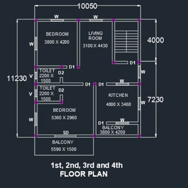
And fill the required text in drawing as shown below
Click on ANNOTATION tab
Click on Dimension
Click > Manage dimension style
Style name > Project
Set the characteristics of dimensions as
Select the yellow colour for the dimension style and extension line
Select arrowhead size as 200
Select the text as Cyan colour
Select Text Style > Project
Text Height > 300
Then select linear dimensions
Provide the required dimensions
The 1st, 2nd, 3rd and 4th floor plan is ready
To create the terrace floor plan
Copy the ground floor plan
By using offset command
Provide the wall thickness of 230 to show the parapet thickness
Provide the dimensions as per
3D Setting
Select workspace switching > 3D Modelling
Select Visual style control > 2D Wireframe
Use the 3D orbit command to set it in proper position
Selection of Layers
Click on layer properties
Click on new layer
Give the layer name > 3D Wall
Turn the layer ON
Set Unlock
Slect layer colour > Cyan
Similarly, use this above process to provides the layer
The layers which are assigned are shown in below fig

Steps to draw 3D staircase
Set the current layer as > Staircase
Take a line command
Specify first point > Anywhere in the drawing
Specify next point as > @0,0,165 > Enter
Specify next point as > @250,0,0 > Enter
Specify next point as > @0,0,165 > Enter
Specify next point as > @250,0,0 > Enter
Specify next point as > @0,0,165 > Enter
Specify next point as > @250,0,0 > Enter
Specify next point as > @0,0,165 > Enter
Specify next point as > @250,0,0 > Enter
Specify next point as > @0,0,165 > Enter
Specify next point as > @250,0,0 > Enter
Specify next point as > @0,0,165 > Enter
Specify next point as > @250,0,0 > Enter
Specify next point as > @0,0,165 > Enter
Specify next point as > @250,0,0 > Enter
Specify next point as > @0,0,165 > Enter
Specify next point as > @250,0,0 > Enter
Specify next point as > @0,0,165 > Enter
Specify next point as > @900,0,0 > Enter
Enter
Provide the weist slab of 100 by using line and offset command
Take the boundry command
Pick internal point
Select the internal portion of staircase
Enter
Visual style control > Shaded
Take extrude command
Extrude the stairs at 1115
Take 3d Rotate command
By using this command put the staircase as per direction
Select all the staircase
Take copy command
And place it in proper position to create the next flight
Use the 3D rotate command to place the last flight of the staircase in proper position
Take a circle command
Specify centre > At railing position
Click > Diameter
Specify diameter > 50
Enter
Extrude that circle at a height > 900
Copy that cylinder and place it in a proper position
Use the line and sweep command to draw the horizontal handgrill
The staircase is ready
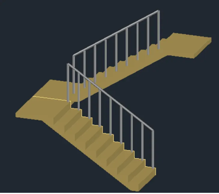
To set the above view
Go to > Visyalise tab
Click > View Manager
One dialogue box will open
Click > New
Specify View name > Staircase view
Enter
Set current
Enter
The Staircase view is saved
Steps to create the 3D Door and Windows
Change the layer as per requirement
Take the rectangle command
Specify first corner point > Anywhere in the drawing
Click > Dimension
Specify length > 1000
Specify width > 2000
Take offset command to show the door frame
Take offset distance > 75
Select object > Rectangle
Again take offset command to show the mullion
Take the offset distance > 50
Use the region command and substraction command to make it 3D
Take the extrude command
Select object > Door frame
Extrude it at a distance > 100
Take the extrude command
Select object > Mullion
Extrude it at a distance > 50
Take the extrude command
Select object > Door
Extrude it at a distance > 10
Use the move command to set all the components in a proper manner
Use the rectangle, extrude command to provide the architectural view
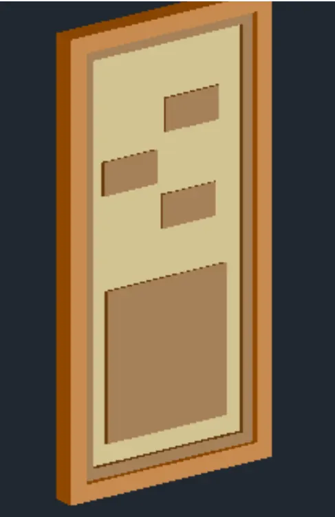
Take the rectangle command
Specify first corner point > Anywhere in the drawing
Click > Dimension
Specify length > 900
Specify width > 2000
Take offset command to show the door frame
Take offset distance > 75
Select object > Rectangle
Again take offset command to show the mullion
Take the offset distance > 50
Use the region command and substraction command to make it 3D
Take the extrude command
Select object > Door frame
Extrude it at a distance > 100
Take the extrude command
Select object > Mullion
Extrude it at a distance > 50
Take the extrude command
Select object > Door
Extrude it at a distance > 10
Use the move command to set all the components in a proper manner
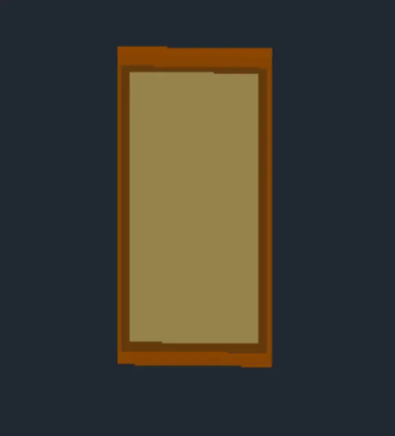
Take the rectangle command
Specify first corner point > Anywhere in the drawing
Click > Dimension
Specify length > 1200
Specify width > 1500
Take offset command to show the window frame
Take offset distance > 75
Select object > Rectangle
Again take offset command to show the mullion
Take the offset distance > 50
: Use the region command and substraction command to make it 3D
Take the extrude command
Select object > Window frame
Extrude it at a distance > 100
Take the extrude command
Select object > Mullion
Extrude it at a distance > 50
Take the extrude command
Select object > Window
Extrude it at a distance > 10
Use the move command to set all the components in a proper manner
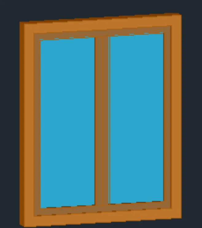
- Use the similar process to prepare all the Sliding door and ventilator
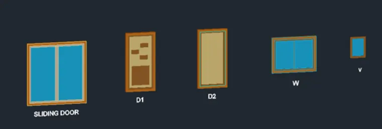
Steps to draw the 3D Building
Copy the first and second floor plan
Erase all the unwanted things such as text, dimensions etc. from the copied plan
Change the corrent layer to 3D wall layer
Take boundry command
Pick internal point
Select the internal portion of staircase
Enter
Visual style control > Shaded
Take extrude command
Extrude the Wall at 2870
It will shows the following result
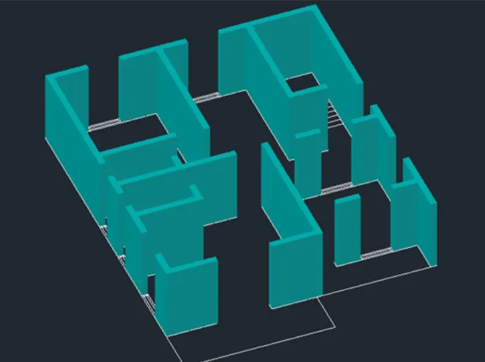
Take the ucs command
Select any wall havng window
Take a rectangle command
Specify corner point > Corner of window
Specify other point > Click on opposite corner point
Enter
Move that rectangle in Z-axis at height of 900 to show the window seal level
Take copy command
Copy theat rectangle in Zaxis at height of 1500
Extrude both the rectangles and take union command
Select the object > Wall and extruded part
Enter
Similarly by using this same process, provide the space for window as well as for doors and ventilators
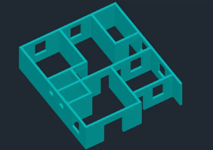
Go to staircase view drawn before
Use the copy command
Copy that staircase in a building in proper way
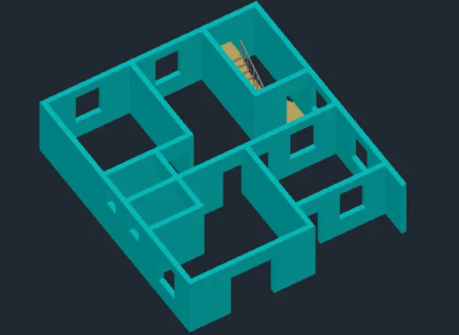
To set the above view
Go to > Visualise tab
Click > View Manager
One dialogue box will open
Click > New
Specify View name > V1
Enter
Set current
Enter
The v1 view is saved
Use the UCS command
Copy all the respective doors and windows
Place it in a proper position
The first floor is ready
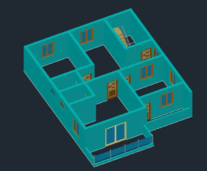
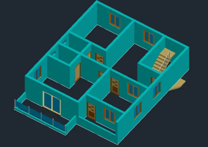
Similarly use the above methods to create 3D of the Ground floor
In 3D grund floor view, the colums are visible
Take region command
Select
Use the extrude command to show its height
From the staircase view copy the staircase and place it in a proper position
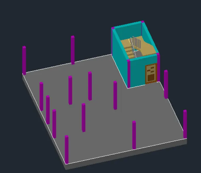
To set the above view
Go to > Visualise tab
Click > View Manager
One dialogue box will open
Click > New
Specify View name > GF View
Enter
Set current
Enter
The GF view is saved
Similarly use the above methods to create 3D of the Terrace floor
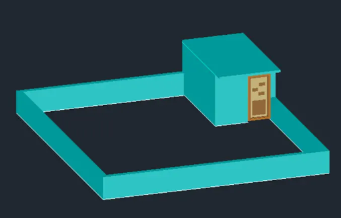
To set the above view
Go to > Visualise tab
Click > View Manager
One dialogue box will open
Click > New
Specify View name > TF
Enter
Set current
Enter
The TF view is saved
Enter
Take a rectangle command
Specify corner point > Anywhere in the drawing
Click > Dimension
Specify Length > 10050
Specify Width > 12230
Enter
Make it region
Use the flooring material to rectangle
Copy the first floor
And place it above the rectangle flooring
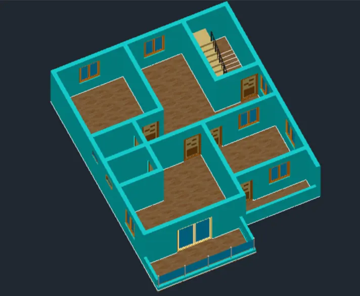
Take copy command
Select object > Select the above object
Place it on the ground floor in proper manner
Take move command
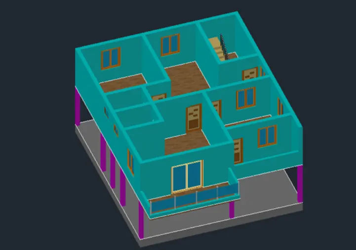
Take Copy command and copy the second floor over the first floor
Similarly put all the floors
Enter
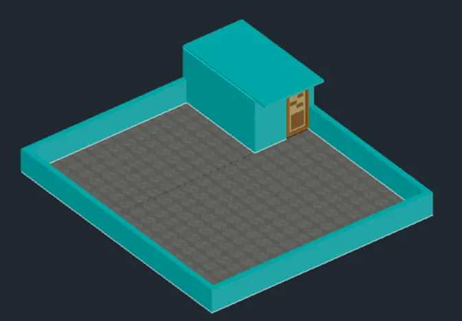
Take a rectangle command
Specify corner point > Anywhere in the drawing
Click > Dimension
Specify Length > 10050
Specify Width > 12230
Enter
Make it region
Use the flooring material to rectangle
Copy the Terrace floor
And place it above the rectangle flooring
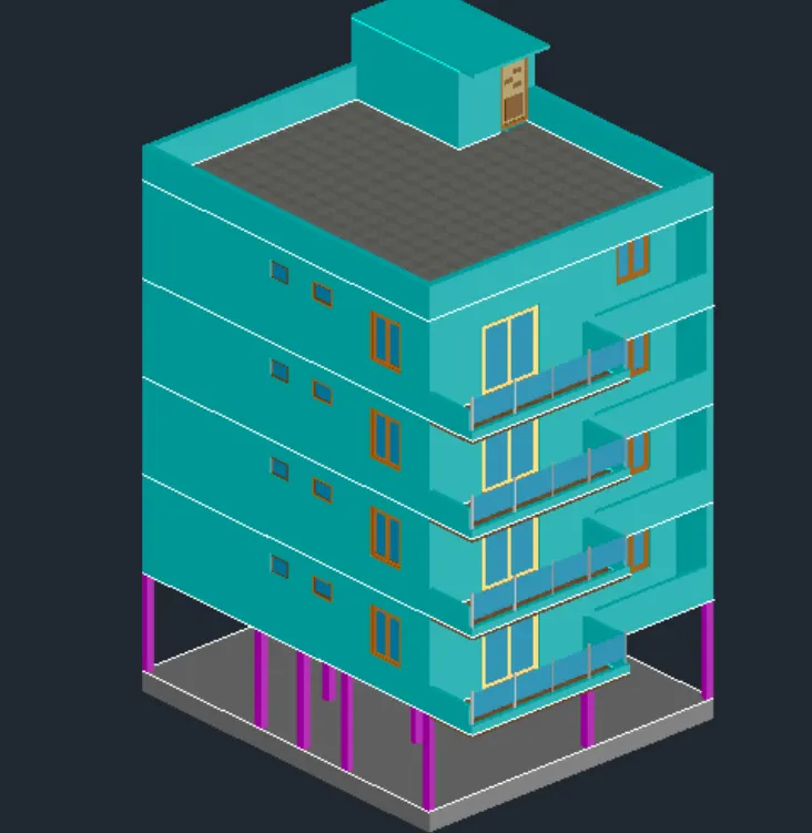
Move this terrace floor
Put it on the building
Steps to provide the material
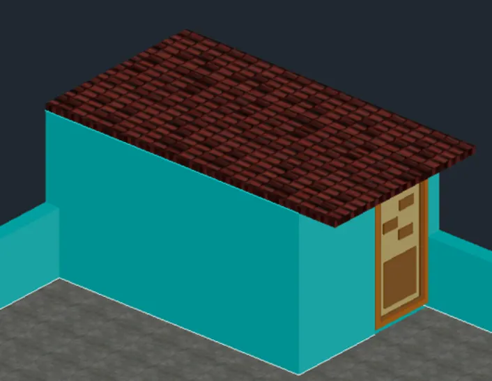
Take material browser command
Select Autodesk library > Roofing
Select Roofing > Spanish – Red 3 > Add to material
Selct the roofing part > Assign the material
Enter
Take material mapping command
Use it in a proper way, to see material in appropriate manner
Switch visual style control > Realastic
The roofing material is ready
Take material browser command
Select Autodesk library > Wall paint
Select wall paint > Pearl > Add to material
Selct the wall part > Assign the material
Enter
The wall paint is ready
Take material browser command
Select Autodesk library > Wall paint
Select wall paint > white > Add to material
Selct the projection > Assign the material
Enter
Assign all the materials which are necessary
Take rectangle anywhere in the drawing
The rectangle should be more than the ground floor area
Make it region
Extrude it below > 100
The wall paint is ready
Take material browser command
Select Autodesk library > Concrete
Select Concrete > Block > Add to material
Selct the rectangle> Assign the material
Enter
Move the building on that rectangle
Steps to set the Camera
Take a circle command
Place it at left bottom corner
Extrude it at height > 5000
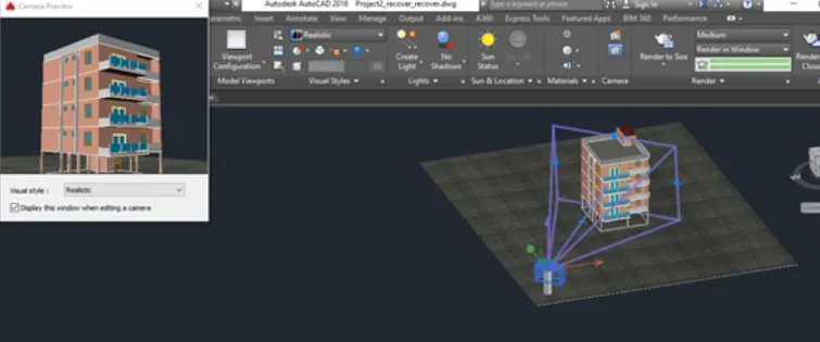
Click > Visualise > camera
Name it as > Cam1
Set target
Delete the cylinder
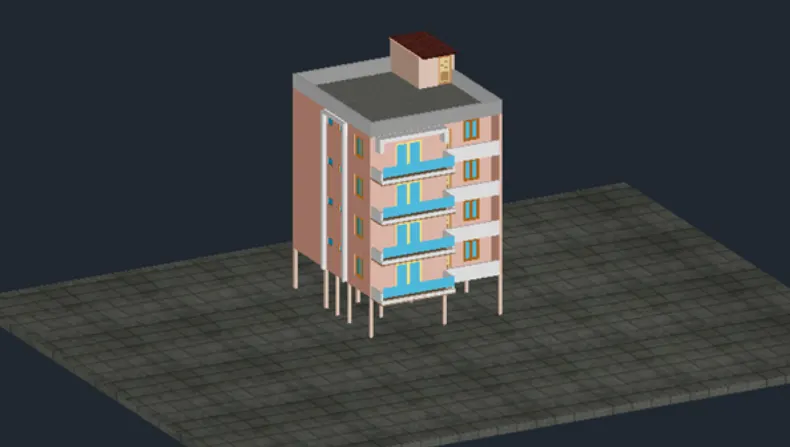
Click on the camera it will gives the following result
Steps to set the Distant light
Take a circle command
Place it at right bottom corner
Extrude it at height > 20000
Click > Visualise > Create light > Distant light
Name it as > Sun light
Set target
Set intensity > 100
Delete the cylinder
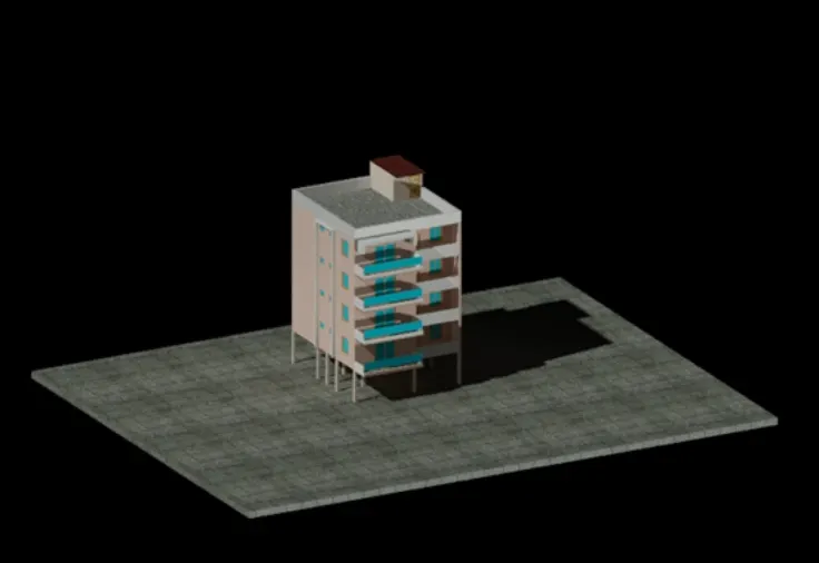
Take rr command to see the effect
Save this image
Steps to set the exposure condition
Select visualise tab > Render > Click dropdown
Render environment and Exposure
Select Environment > ON
Click > Use custom Background > Gradient
Select top colour > Blue
Select bottom colour > White to represents the sky
Enter
Click on sun status
Select time and date
Date as
Time as > 5:30PM
Enter
Click on > Render preset manager
Render in > View port
Render
The 3D model of residention building is ready with rendering views.
View 1:
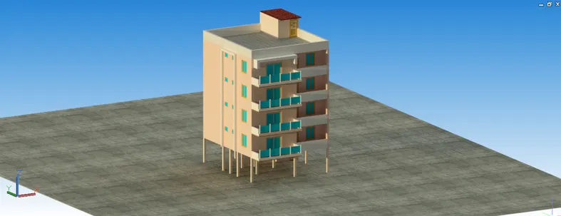
view 2:
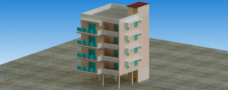
view 3: