Project 2_Analyze and Design the RC office building as per IS standard code in TEKLA STRUCTURAL DESIGNER
Develop general arrangement for the RC office building. Analyze and design the building as per IS standard code in TEKLA STRUCTURAL DESIGNER. Refer the attached plan and elevation. The building to be designed for dead, live, wind and seismic loading.
Report of each member to be generated and extract drawings for structural plans, beam reinforcement details from the software
AIM:
- To develop as per the given plan and design the structure.Also, to analyze and design the building as per IS standard code in TEKLA STRUCTURAL DESIGNER from the attachment.
INTRODUCTION:-Tekla structural Designer is used for modelling, analyzing and designing of RC structure. Modelling is done based on selecting each member in the model tab and properties are assigned. Loading (ie, dead, live , wind and seismic ) of each member is done and validated. 1st order linear analysis is done for the model and bending moment, axial force, shear force and deflection diagram is obtained in result view. Interactive Design for each member is done to check if the design criteria satisfy.
PROCEDURE:
- Take the screenshorts of the plan and open them in paint
- Draw the positions of columns and beams in point.
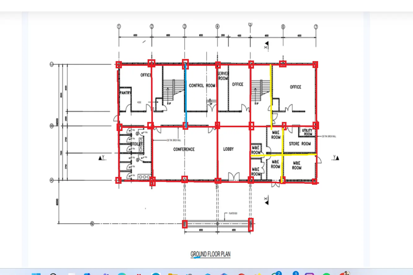
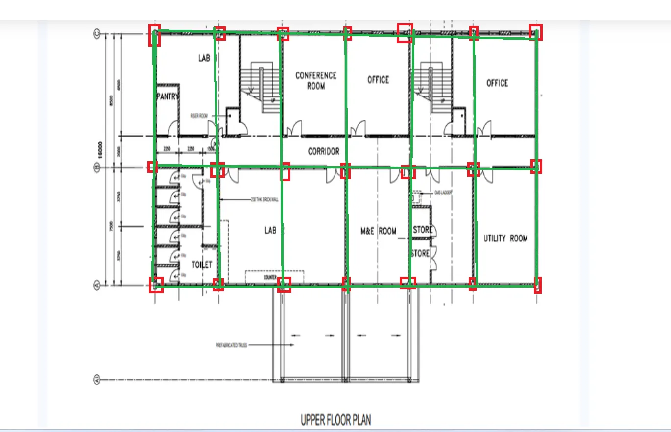
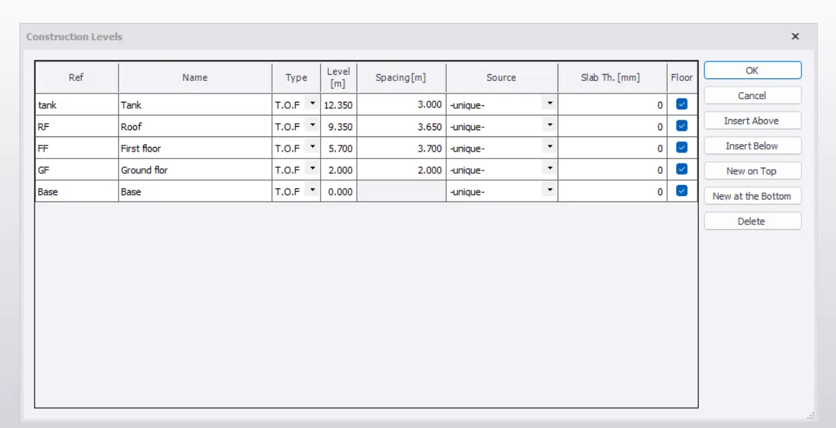
- Open Tekla file and create the construction levels for the structure according to the plan.
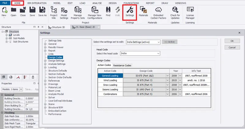
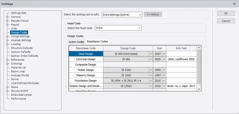
- Under Home TAB, select settings. Set to Indian Standards code.
- Set Design code as shown below.
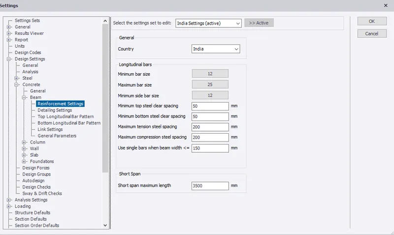
- Set reinforcement settings for concrete beam.
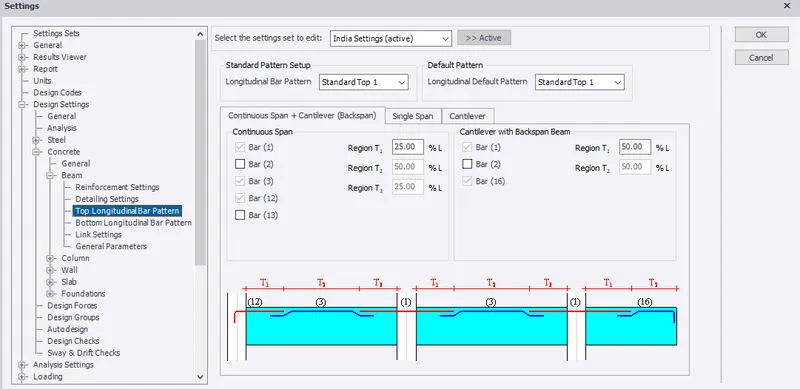
- Set top longitudinal bar pattern details for continous + cantilever beams as shown below.
MODELLING
Construction Level and grid line.
- Refer the plan and section drawings.
- Select construction level from Model tab.
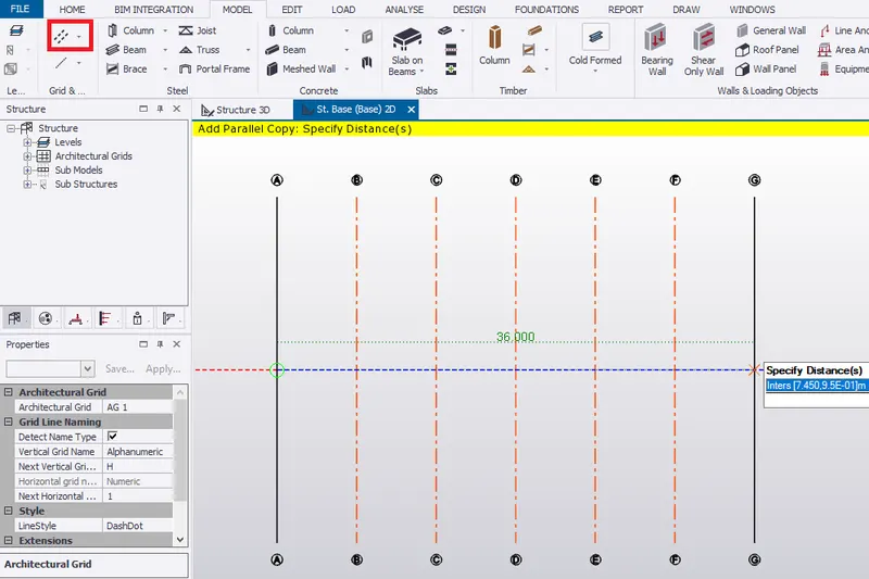
- Select the grid line from Model tab.
- Add the grid line by picking the points on the scene view.(ie, base level).
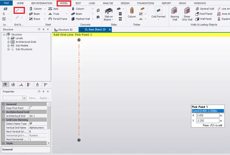
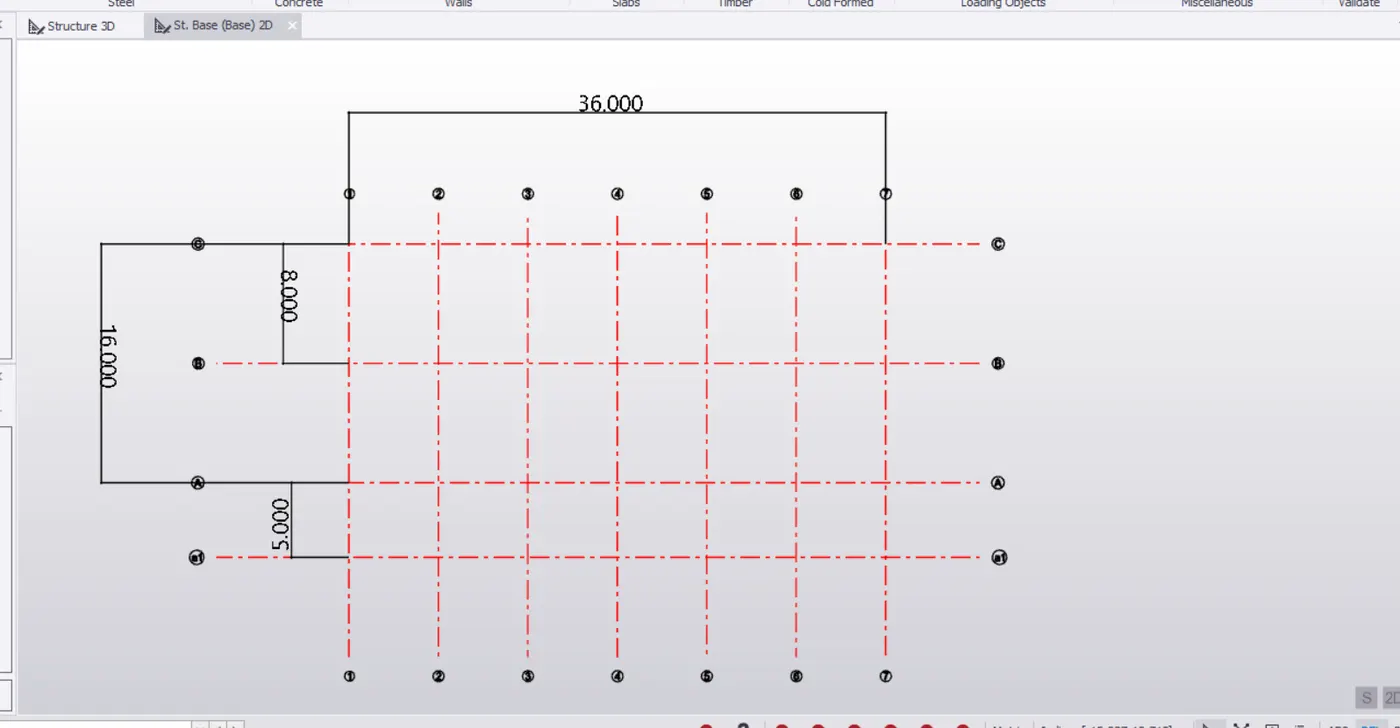
- Construct horizontal vertiacal grid lines.
Modelling of concrete column
- Go to mange property sets, under home tab.
- Select concrete column from members.
- Select the size of the concrete column section used in the construction as per the requirement.
- Set nominal cover as 40mm and releases as fixed.
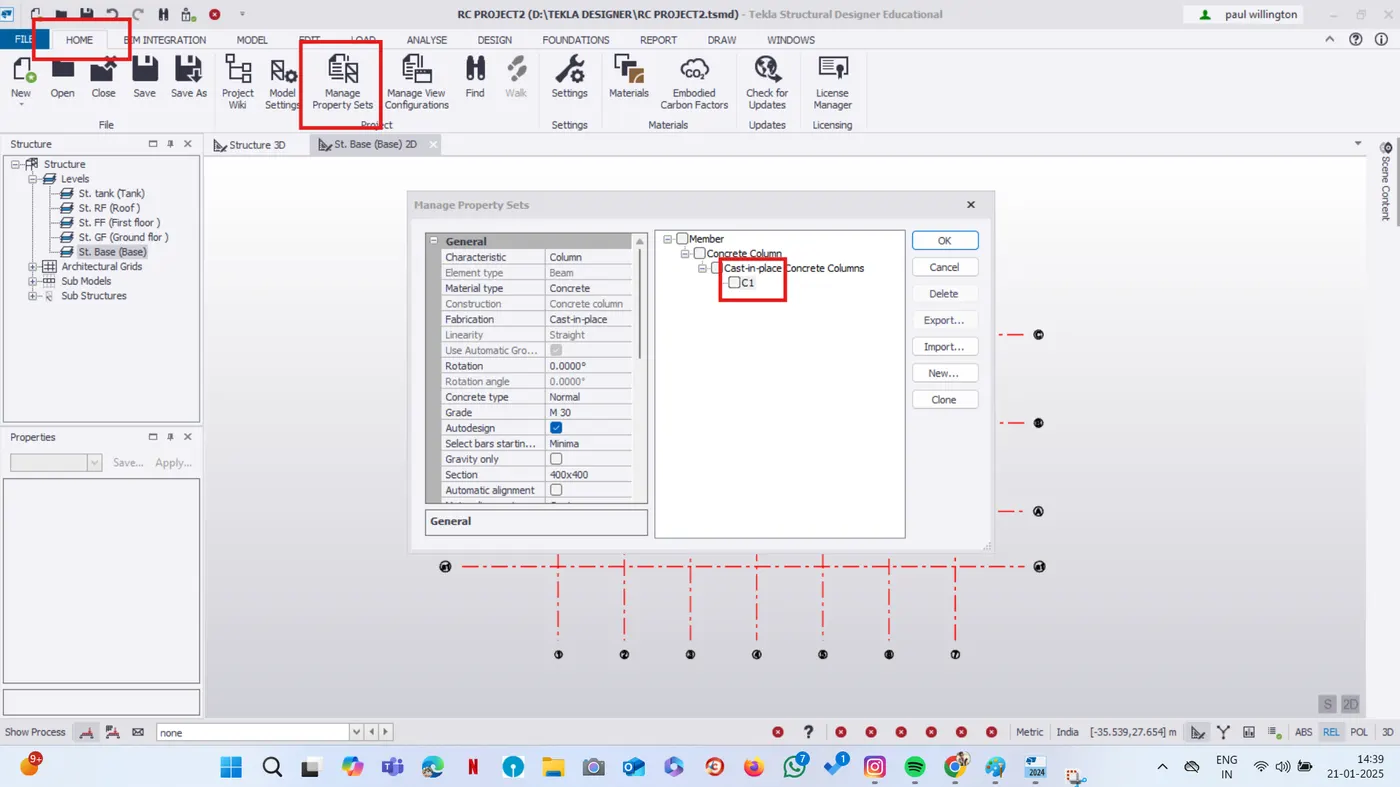
- Go to manage property sets and create members used for the modeling.
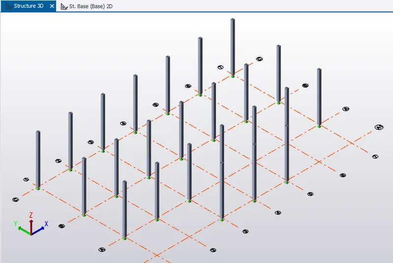
- Go to the model tab and insert concrete columns in the structure.
- Go to the model tab and select the beams tool and draw the beams as per the plan
- We can check the structure in 3D for a neat view.
Modelling of concrete Beam
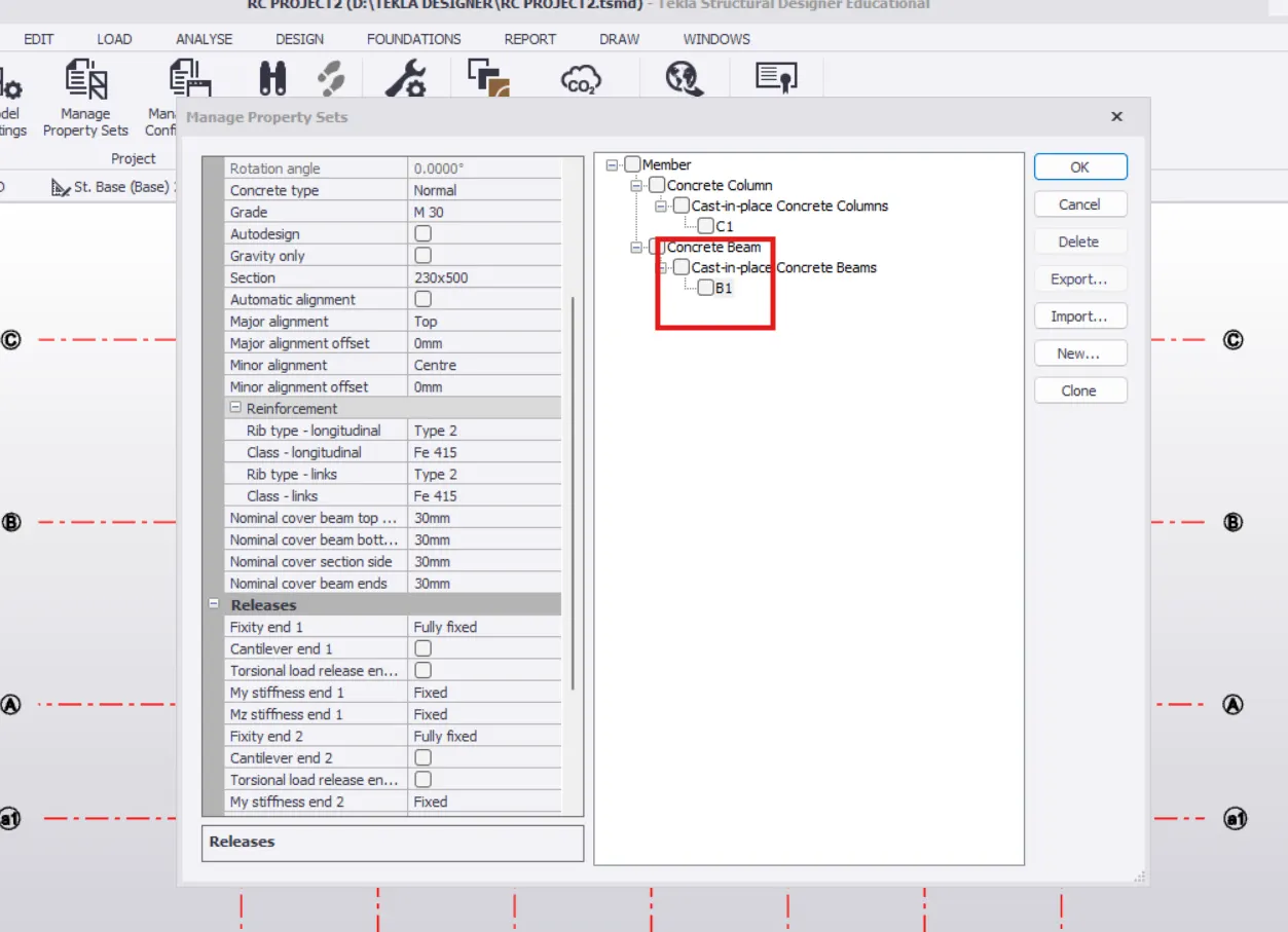
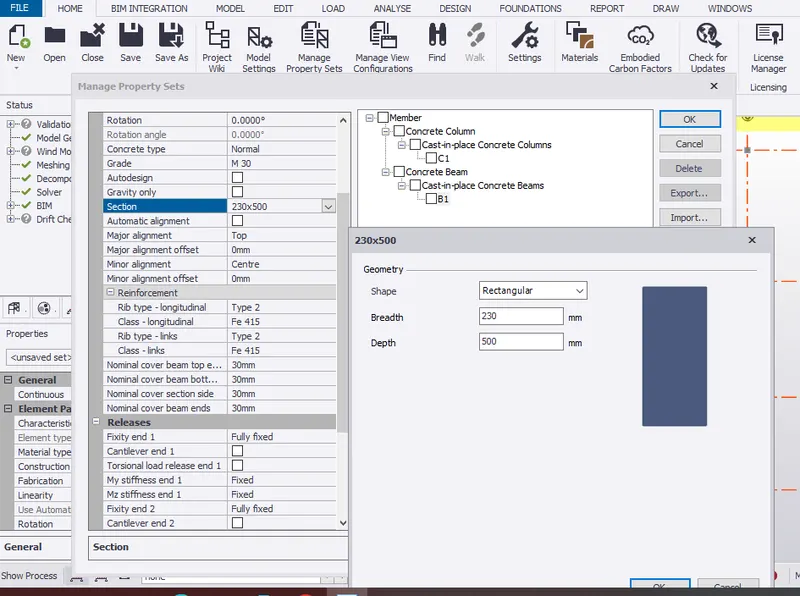
- Go to manage property sets, under home tab.
- Select concrete beam from members.
- Set 230mm x 500mm concrete beam with M30 grade concrete.
- Set nominal cover as 30mm and releases as fully fixed.
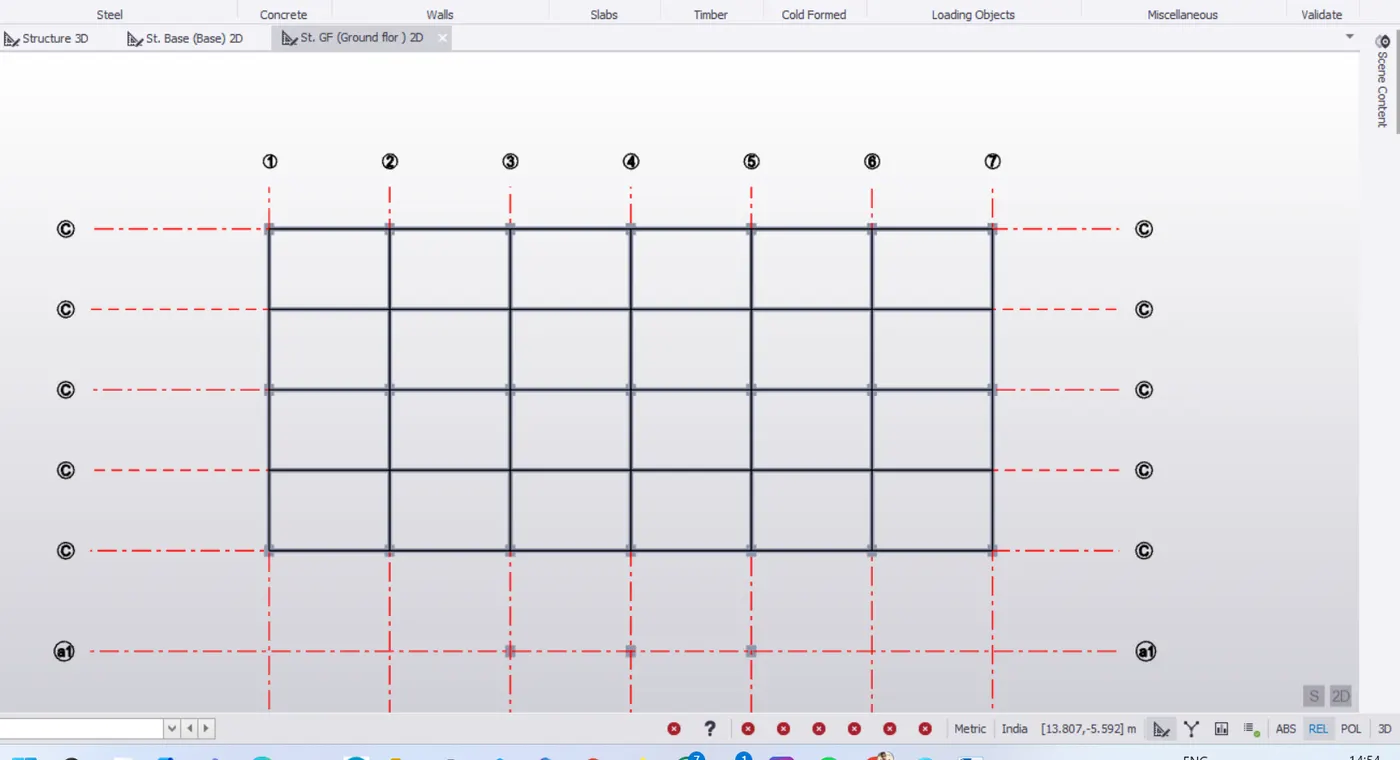
Ground floor
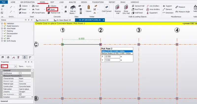
- Go to ground floor in the scene view.
- Select concrete beam from model tab.
- select B1 from Property window and set to simply supported beam.
- Pick points to create concrete beam.
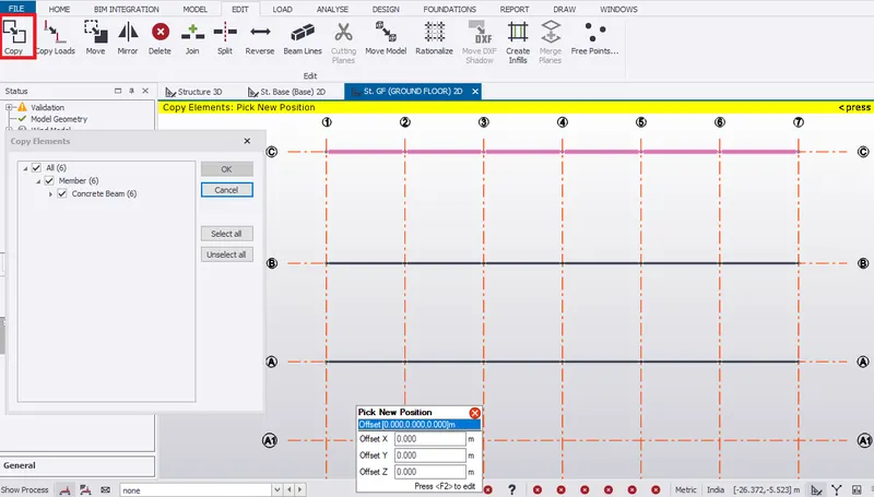
- Copy the beam created to grid line B and A bt picking the reference node.
First floor
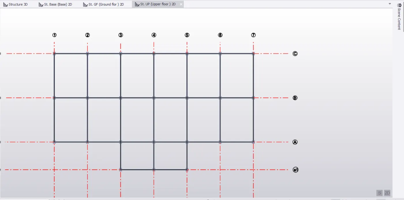
- Go to upper floor in the scene view.
- Select concrete beam from model tab.
- Select B1 property window and set to simply supported beam.
- Pick points to create concrete beam.
- Create concrete beam for gridline C,B and A.
- Validate the model.
- Since the span size of the beam are large, ie, more than 7.5m and 8.5m. Provide secondary beams in between.
- Copy beam B1 as secondary beam at 4.25m from gridline C and 3.75 from gridline B.
Roof Floor
- Go to floor in the scene view.
- select concrete beam from model tab.
- Select B1 from property window and set to simply supported beam.
- Pick points to create concrete beam.
- Create concrete beam for gridline C,B and A.
- Go to manage property sets, under home tab.
- Select concrete beam from members.
- set 230mmx500mm concrete beam with M30 grade concrete.
- Set nominal cover as 30mm and releases as fully fixed at one end and cantilever at other
- Repeat the same process for the levels as per the plan.
- Select slabs on beams and insert slabs for all the floors, where ever required.
- Go to 3D vieww to get a clear view of the slabs inserted.
- Insert frames which will be helpful while applying lods on the structure.
- Add wall panel to the structure.
- Repat the same step for all the walls.
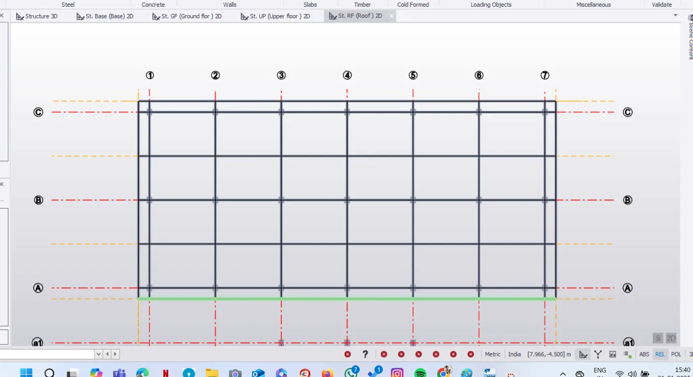
Modelling of cantilever concrete Beam for roof floor
LOADING
(i) Dead Load
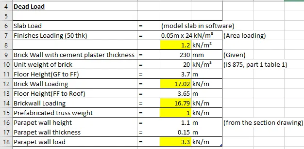
- Data for ded load is calculated and inputed in MS excel as shown below.
- Dead load of the slab is automatically designed by software and applyied to the below.
- Dead load of the slab is automatically designed by software and applyied to the beam.
- Given floor inishes = 50mm and brick wall thickness = 230mm
- Floor finish load = finish thickness x unit weight of concrete
= 0.05m x 24Kn/m^3 = 1.2KN/m2
- Similary, Brick loading for first floor = 16.79KN/m
Ground Floor
- Go to loads and create new load cases.
- Add the dead load on the beams.
- Add the dead loads on the slabs.
- Select the Dead loadcase from the loading tab.
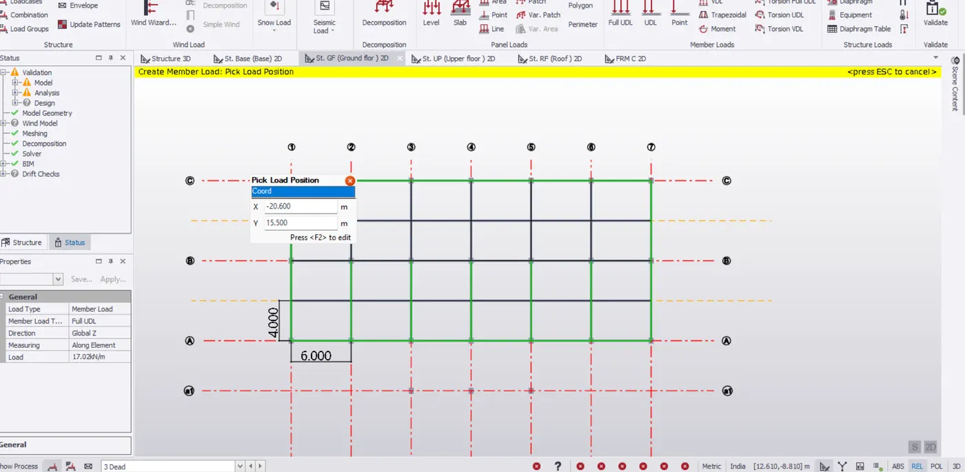
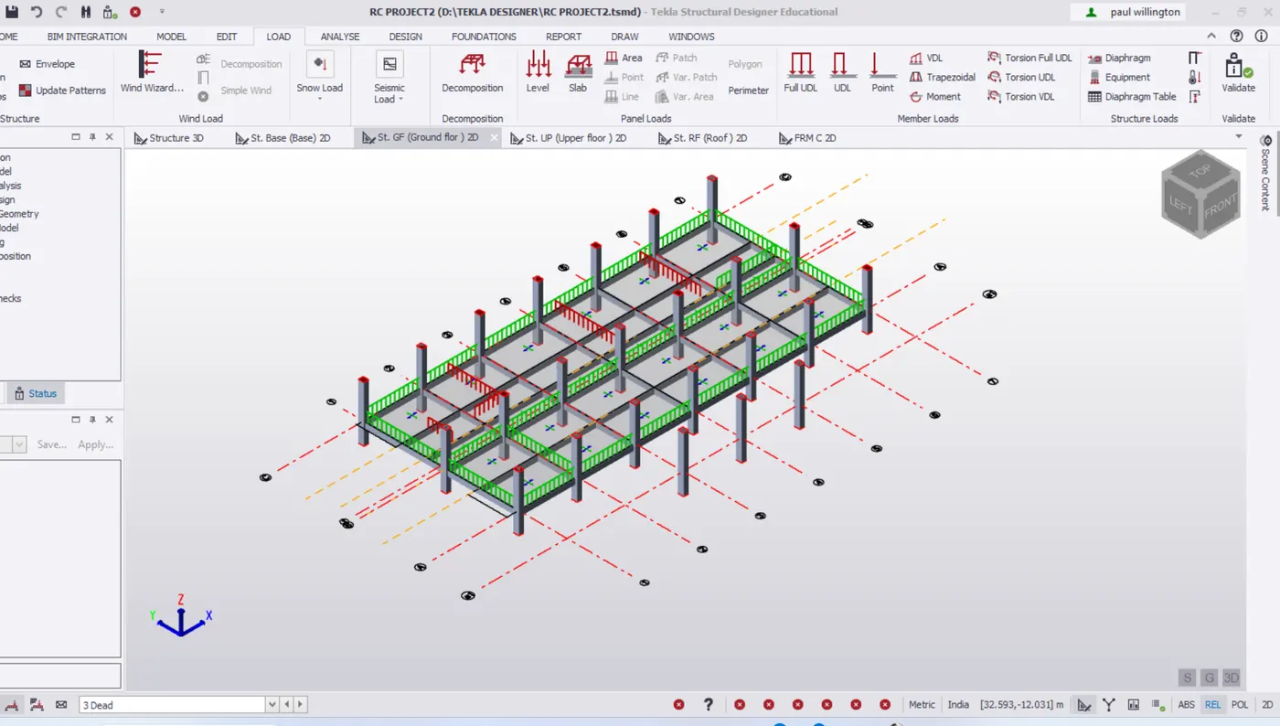
- In the ground floor, select Full UDL from ribbon window to apply the brickwall load of 17.02KN/m.
First floor/Upper floor
- Select the Dead loadcase from the loading tab.
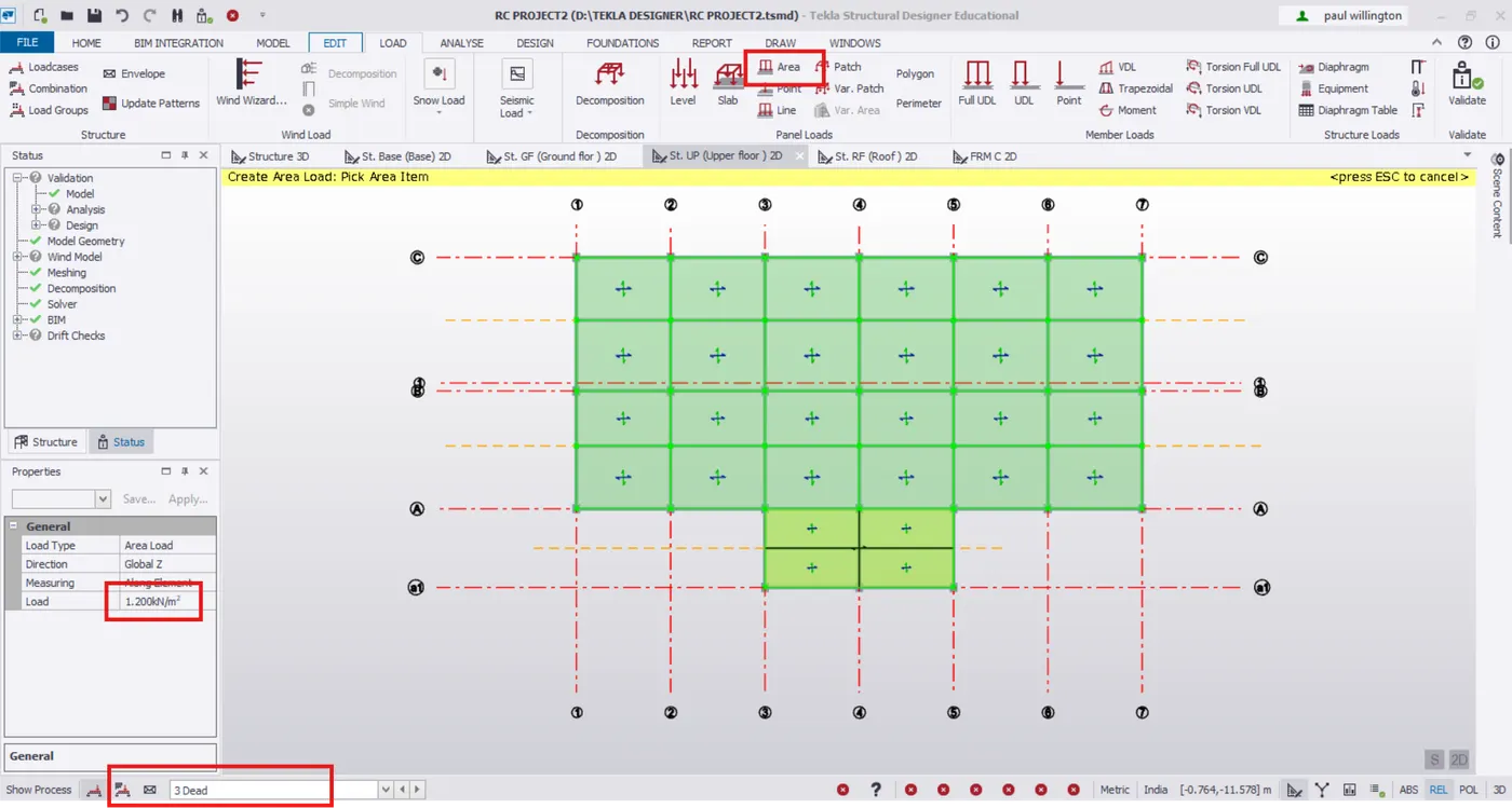
- Select the area load from ribbon window to provide floor finishes load on the slab.
- In propert window, change load to 1.2KN/m2 along global Z- direction.
- Pick the arrea to create load area of 1.2KN/m^2.
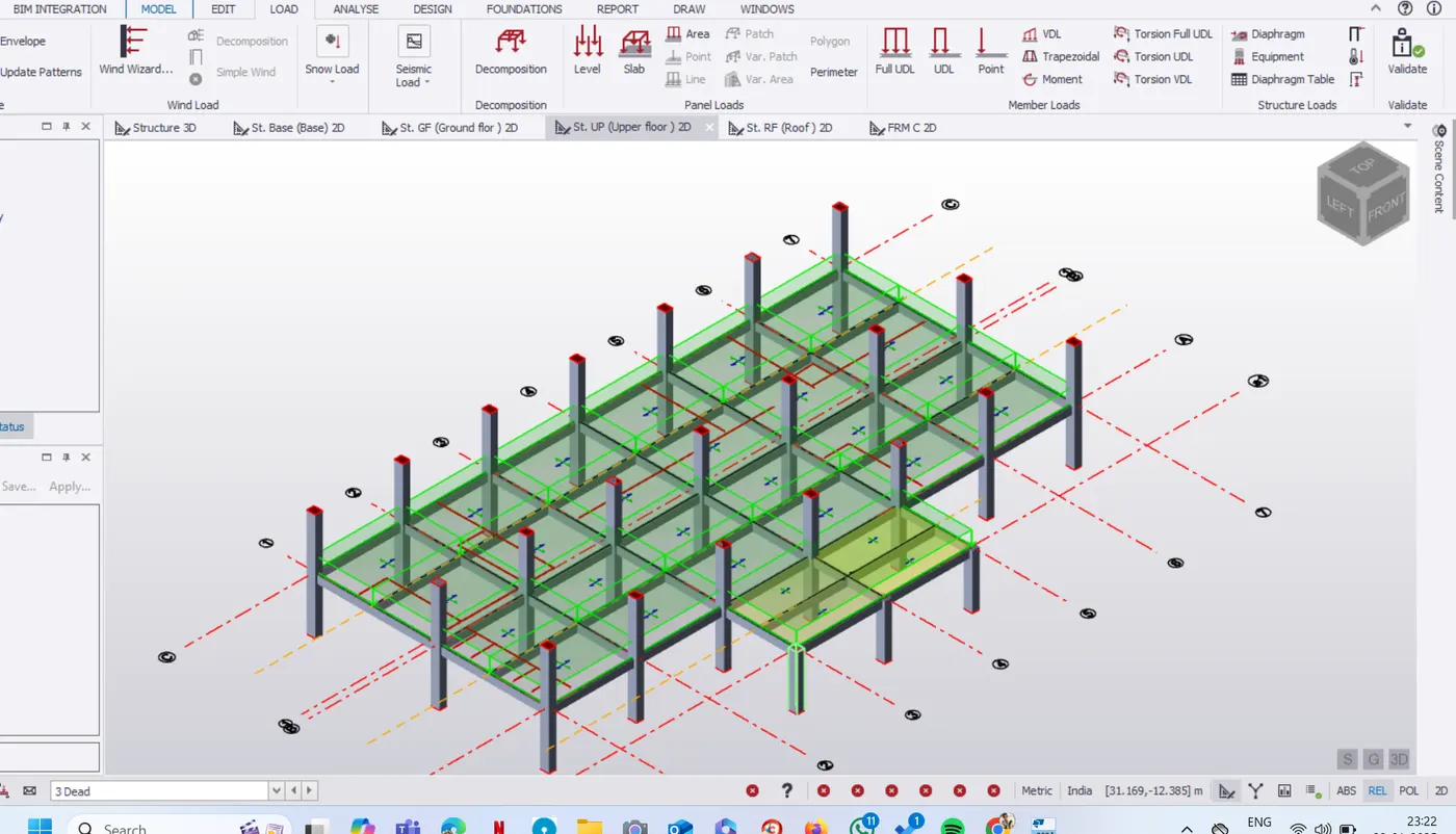
- Apply brickwall load of 16.8KN/m by selecting Full UDL and UDL from ribbon tab under member load.
- Apply prefabricated load of 1KN/m by selecting Full UDL.
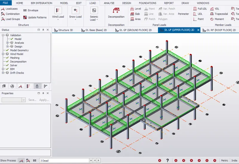
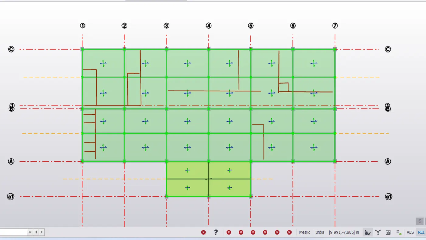
- Therefore, dead loads are applied on the first floor.
Roof floor
- Selecting the Dead loadcase from the loadinng tab.
- Selecting area load from ribbon window to provide floor finishes load on the slab.
- In property window, change load to 1.2KN/m^2 along global Z direction.
- Pick the area to create load area of 1.2KN/m^2.
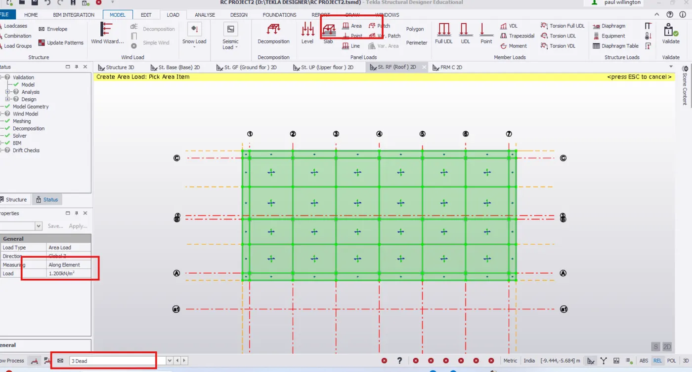
- Apply parapet load on the roof floor.
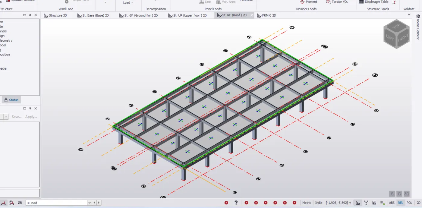
Wind Load
- Firstly, select frame ribbon from model tab.
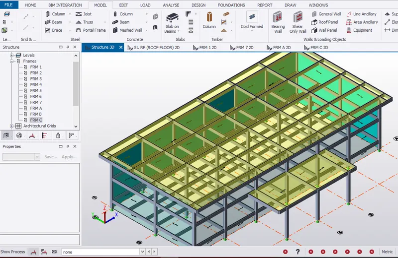
- Pick the grid line to create frames to create wind panes. Therefore, frame are created as
- Pick the grid line to create frame to create wind panels.Therefore, frames are crearted as shown in project window.
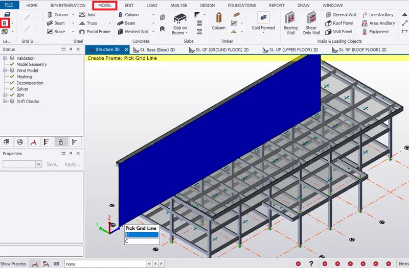
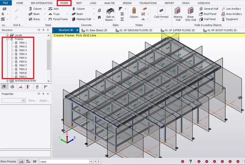
- Selectt frame 1 from project window to create wall panel for the structure.
- Select wall panel from ribbon tab.
- Pick the corners positions of the frames to create wind wall as shown below.
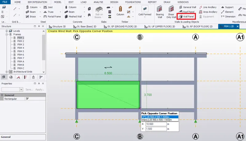
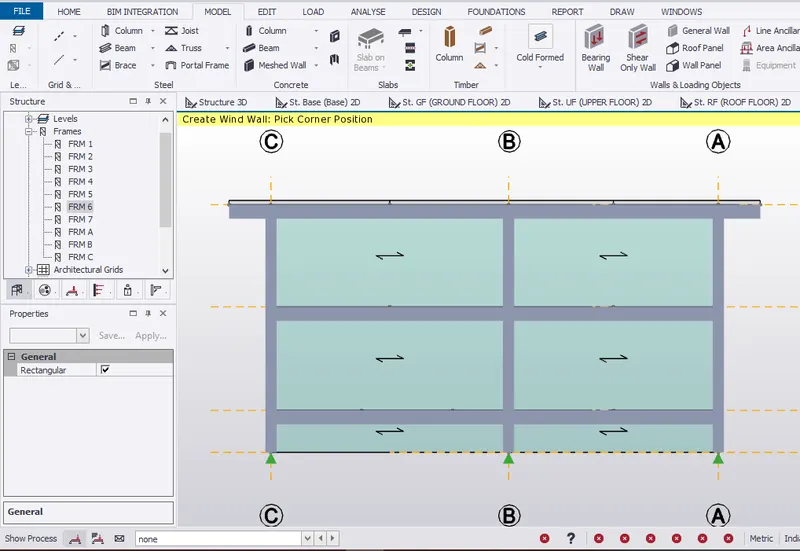
- Similarly, created wall panels for frames 7, A and C.
- Also, create roof panel for structure
- Check in 3D scene view.
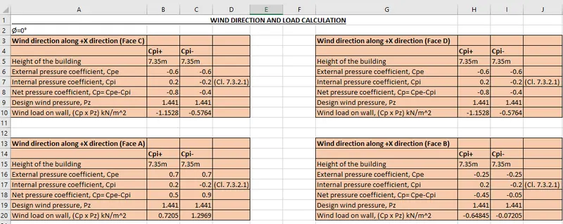
Wind Calculation
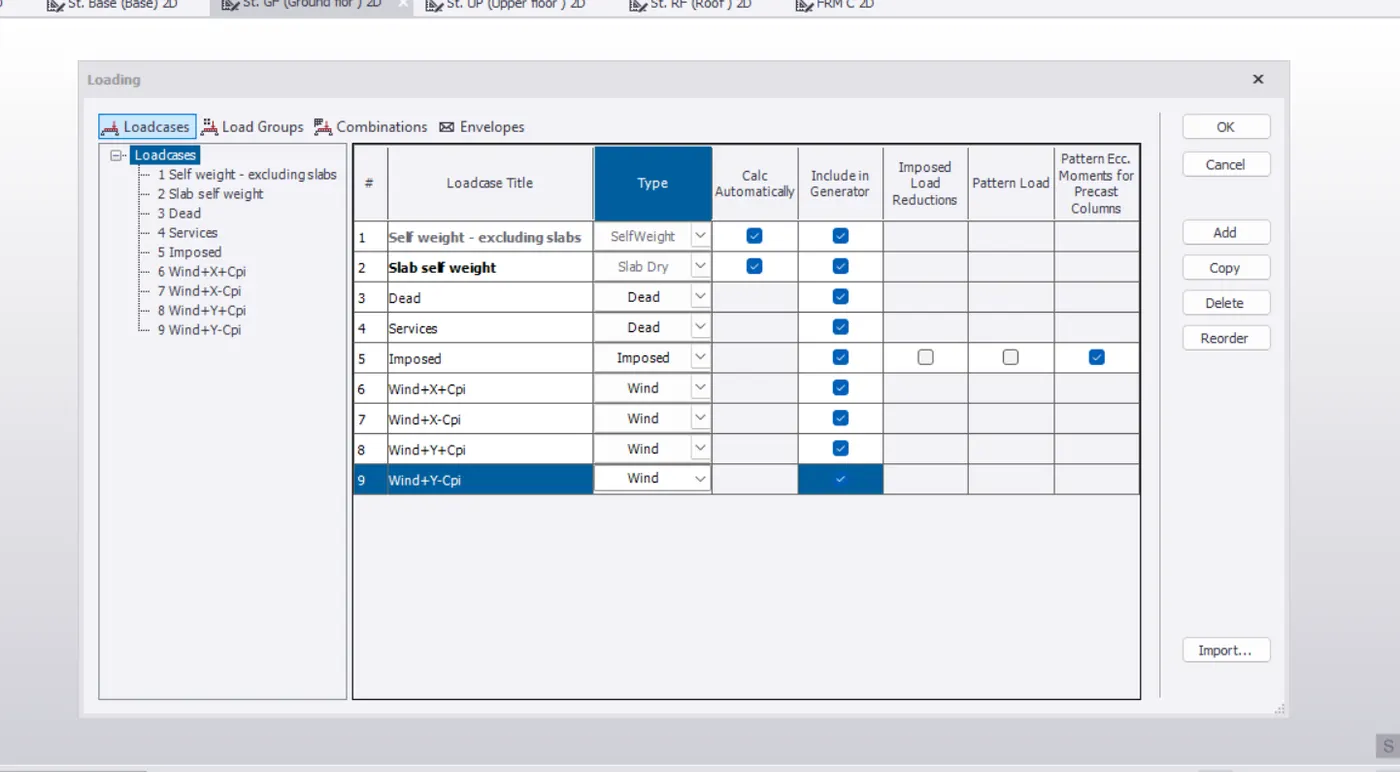
- To create wind load, select load cases from load tab.
- Add loadcases Wind+Y+Cpi, Wind+y-cpi and Wind+x-cpi.
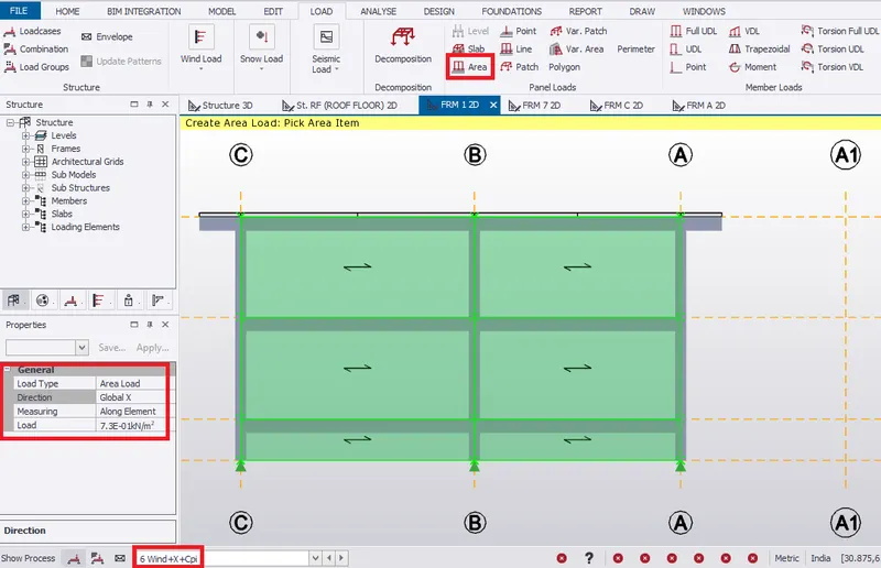
Wind+X+cpi
- Select frame 1 from project window
- Also, select wind +x+cpi from the loading window.
- Slect the area load, change oad intensity to 0.73KN/m^2 and change direction to global X.
- Pick the area to create area load.
- Similary, select frame 7, select Wind+X+cpi from the loading window.
- Select the area load, change load intesity to- 0.65KN/m^2 and chnge direction to gloab x.
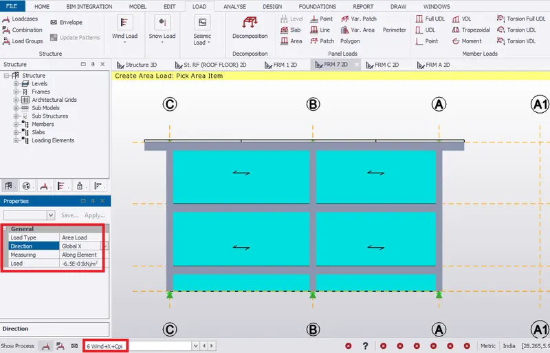
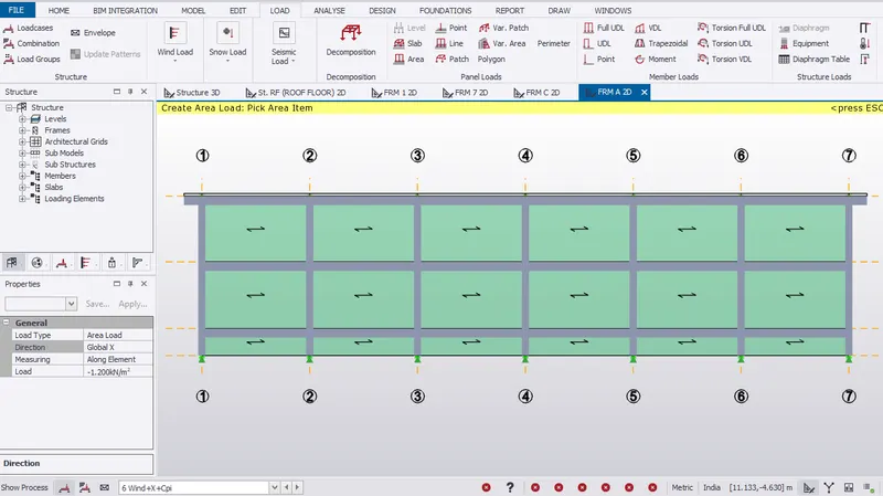
- Check in 3D view.
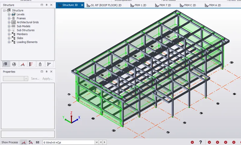
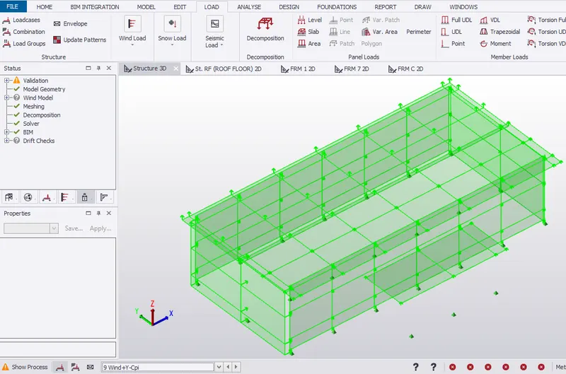
Wind+Y+Cpi
- Trun On the roof panel 3D scene view
- Select area load in load ribbon tab and Wind+Y+cpi from laoding window.
- In property window, set direction to gloabal Z abd load intensity to
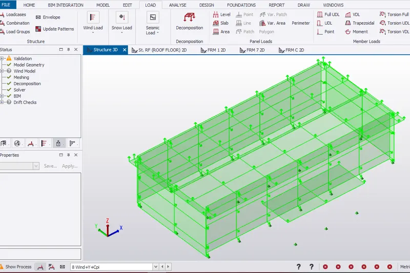
Wind+Y-Cpi
Wind+X+Cpi
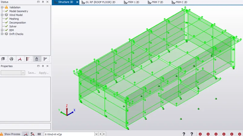
Wind+X-cpi
Seisimic Load
- Select Seismic Load (Seisimic Wizard) ribbon from Load tab.
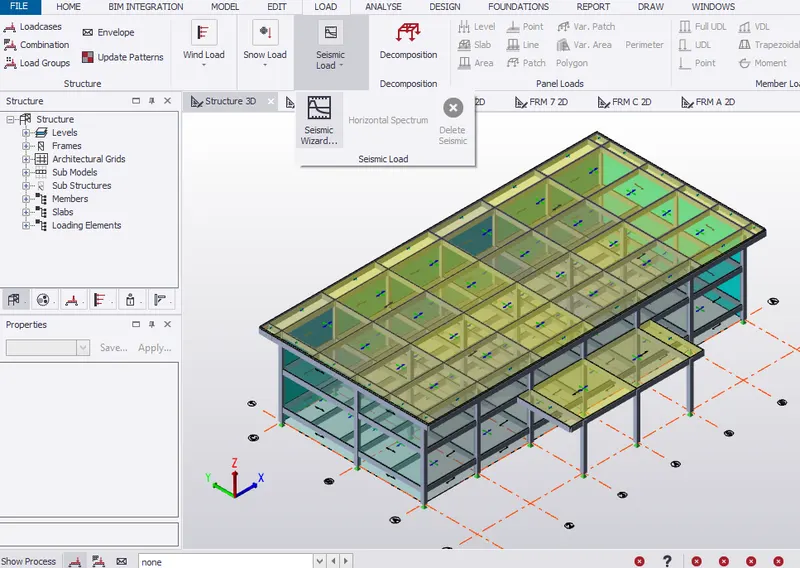
- Select code spectra for analysis procedure. Click Next
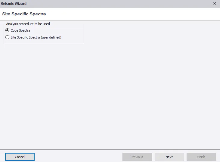
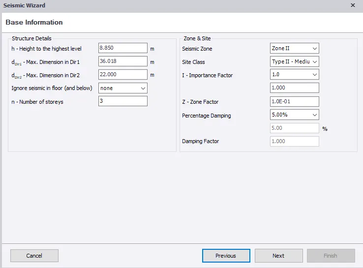
- Structural Deatails under information is automatically inputed.
- Set the seismic zone to 2 and site class to 2 as shown below.
- Importance factor and percentage damping is obtained from Table 6 and 3 respectively of IS1893-1 and Zone factor from Table 2.
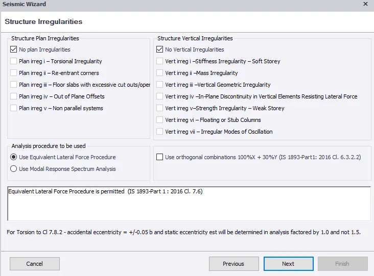
- No structural irregularty in the structure as mentioned in Table 4 and 5.
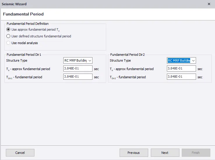
- Use approxmiate fundamental period. Set RC MRF building without any masonry infill in both direction.
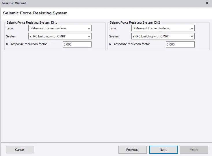
- Set structural type to seismic force resisting system in both direction.
- Select all the loadcase and set factor for imposed load 25% for refered from table 8
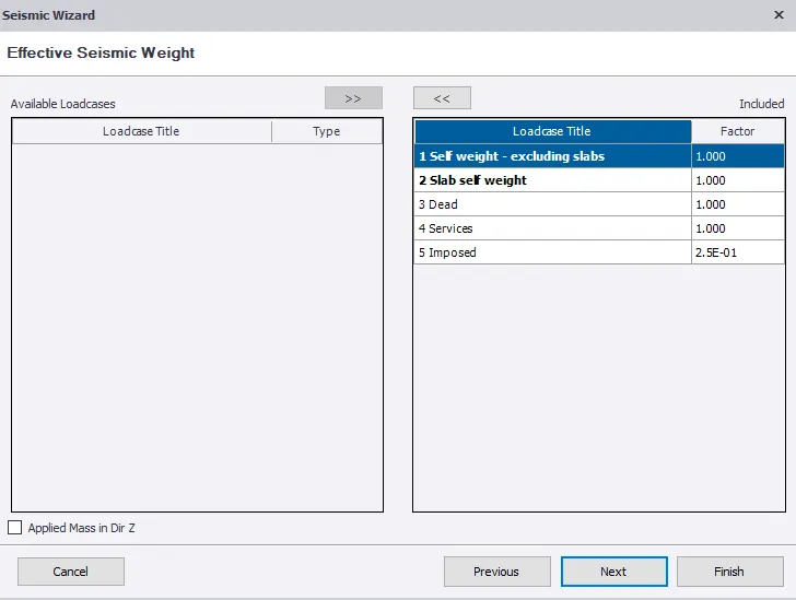
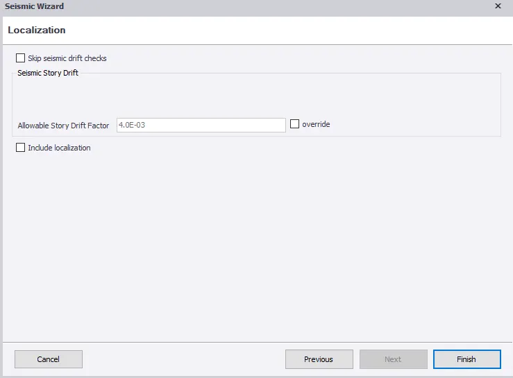
- Set allowable storey drift factor as 0.004. Click finish.
- Delet all previously generated combinations.
- Select the combinations to be generated. Then click on Finish.
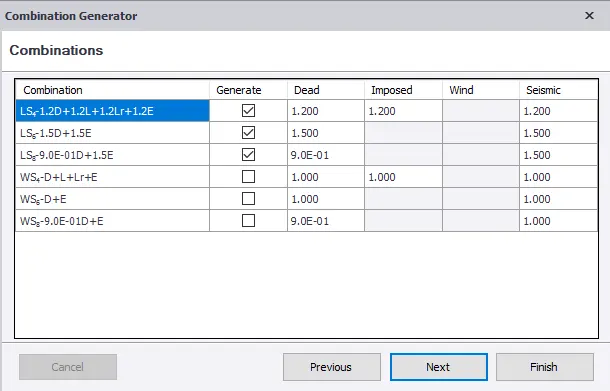
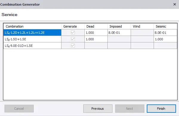
- Select the load combinatio from tab to see the combinatiions generated.
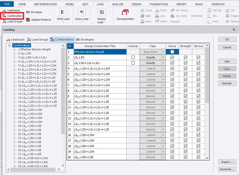
- Validate the model to check any error. Hence, no error.
ANALYSIS
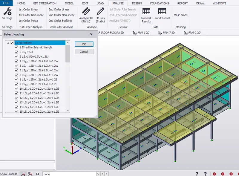
- Go to analyse, select 1st order linear analyse.
- Select all load combinations to run analysis.
- Select all load combinations to run analysis.
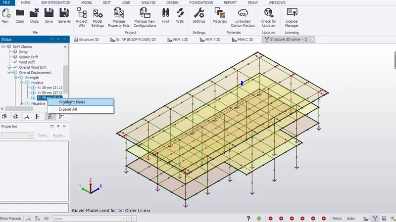
- In project window, highlit the notice with maximu postive displacement
- Therefore, a node is picked in solver view.
Deflection Diagram
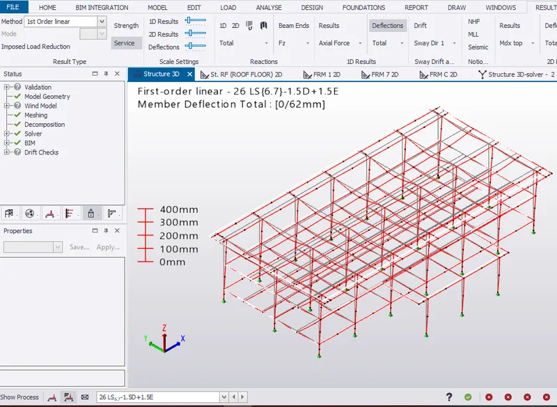
- In results view, under result tab select total defelctions for different load combinations.
- Total defelction for effective seismic weight is 49mm.
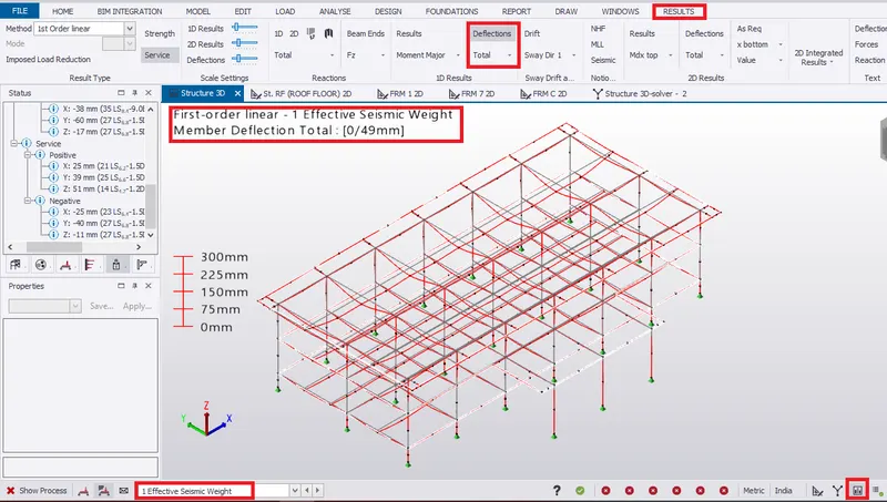
- Therefore, maximum deflection is shown in load combination 26 which is due to seisimc load.
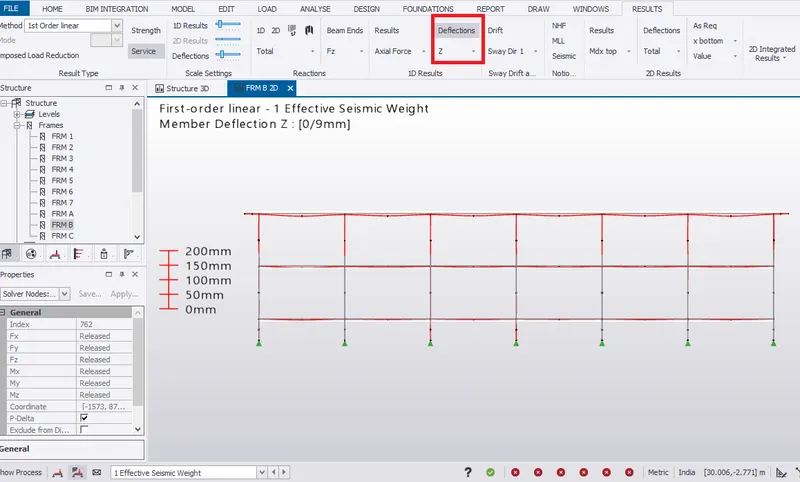
- Select frame B from project window. Check defelction along Z direction in result view.
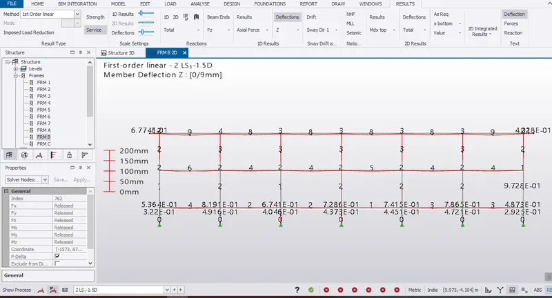
- Defection due to gravity in frame B.
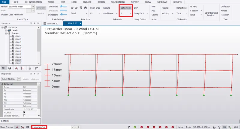
- Deflection due to wind along X direction.
Axial Force Diagram
- Axial force diagram of the column for the structure.
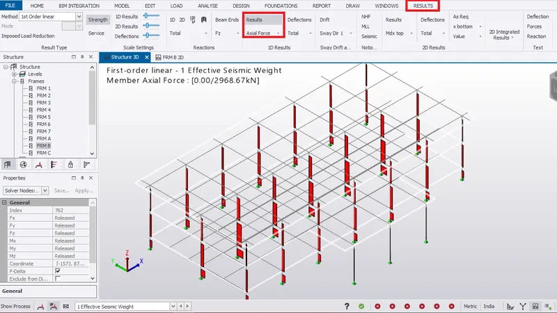
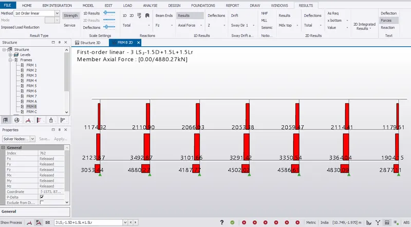
- Similar, select frame B to check axial force diagram.
- Maximu axial force value is shown in load cobination 3 as shown below.
- Also. Check for different load combinations.
Shear Force Diagram
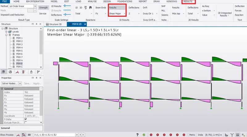
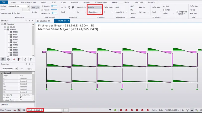
- Select frame B to check shear force major from result tab.
- Check shear major for different load combinations and combinations.
- Shear major for wind load condition.
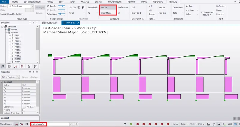
- Shear major for load combination with seismic load.
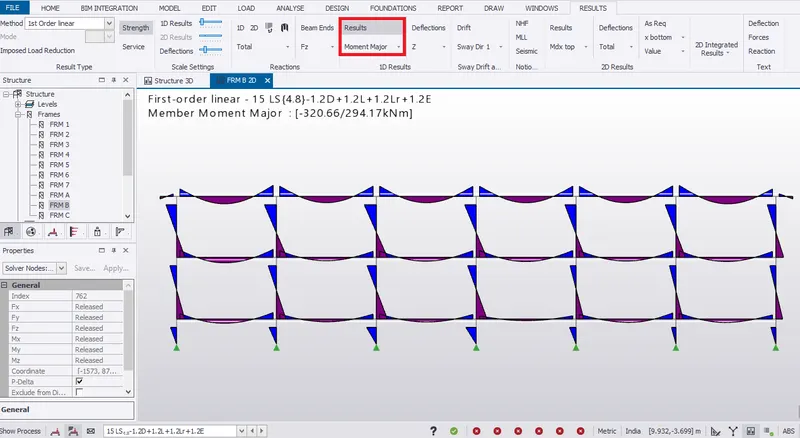
Bending Moment Diagram
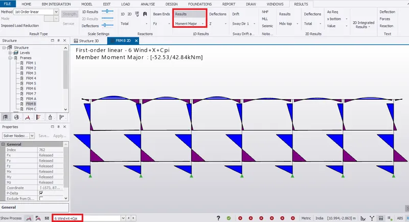
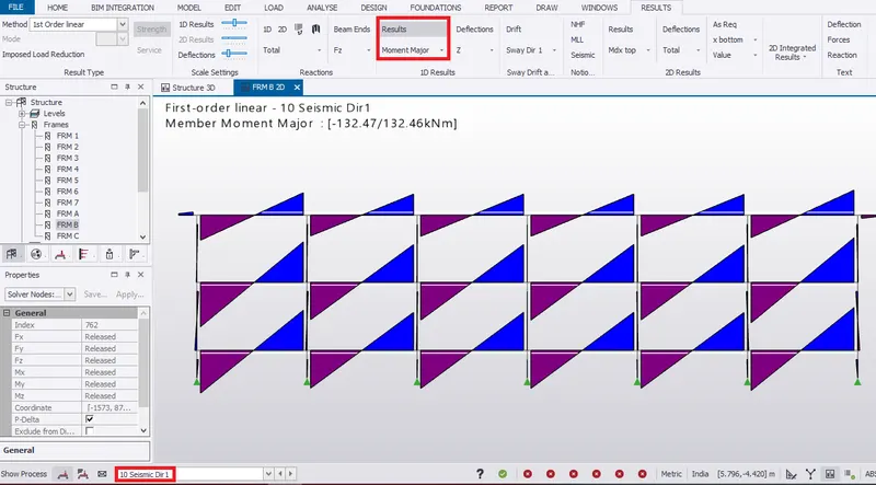
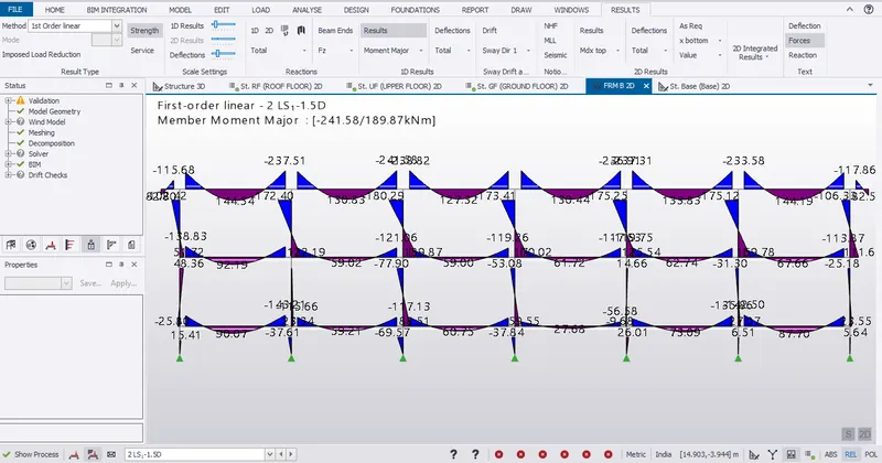
- For frame B, select moment major from result tab.
- Bending maor for wind load condition,
- Bending major for seismic load condition.
Member Design
(i) Slab design
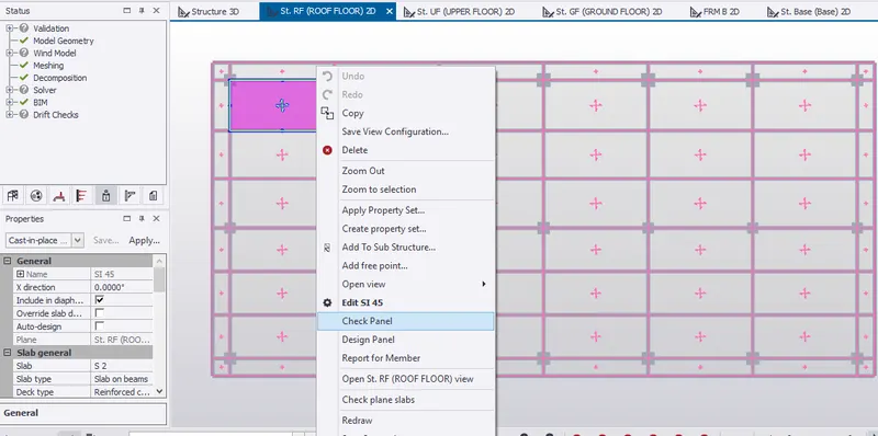
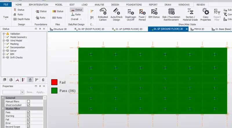
- Go roof floor in scene view. Select a panel to check the panel
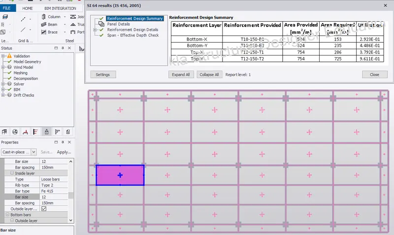
- Provide T12 bars at 150mm centre to center spacing.
- Provide T10 at 150mm spacing as bottom reinforcement and T1 aas top reinforcement.
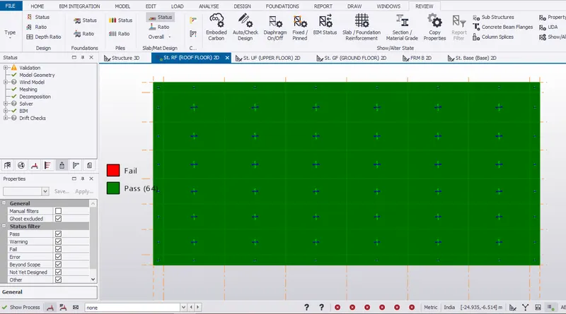
- Check in reive view, the status of the roof slab
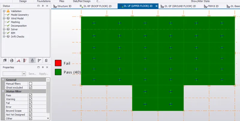
- Similary, check slab panels for ground and first floor.
(ii) Beam design
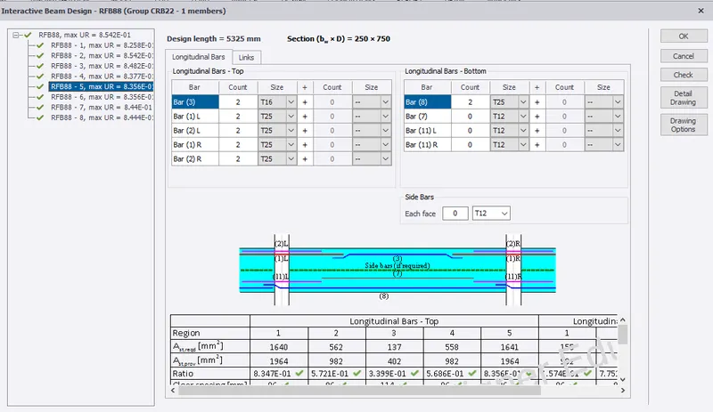
- For frame B, check the maximum bending moment acting in the beam where maximu BM is acting in roof floor.
- Select RF- B88 for interactive design.
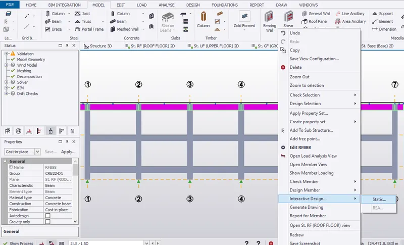
- The beam with section size 230mmx 500mm does not satisfy the design.
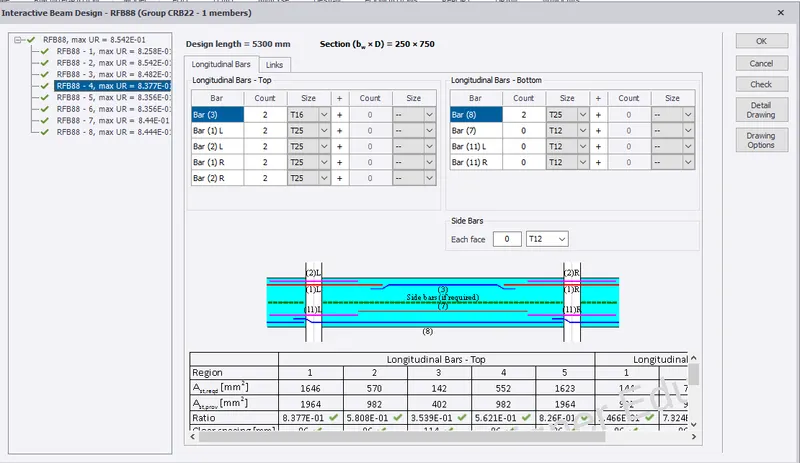
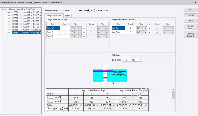
- Therefore , change the section to 250mmx 750mm. Again, interactive design is done.
- Select the first span.Provide t20 and T25 bars. Therefore, UR=0.825
- Similarly, check for each span.
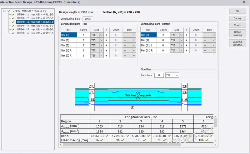
- Select first floor beam UFB40 for interactive dsign.
- Provide section size 230mmx700mm
(iii) Column design
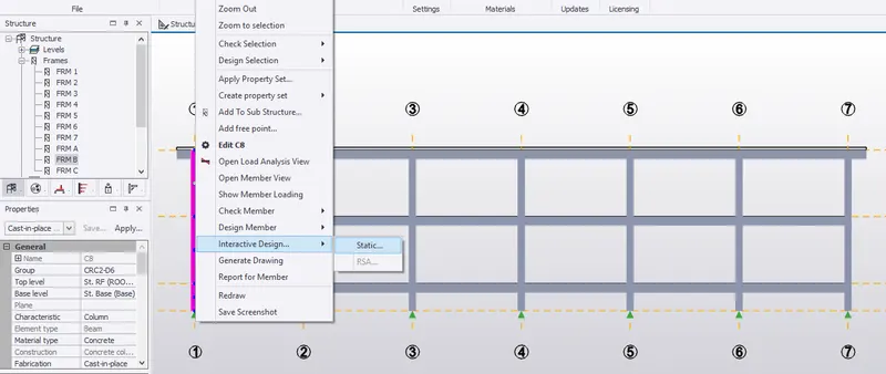
- Select frame B from Project window
- Select the coumn to be designed.
- Right click the member to select interactive Design. Therefore, the member design fails.
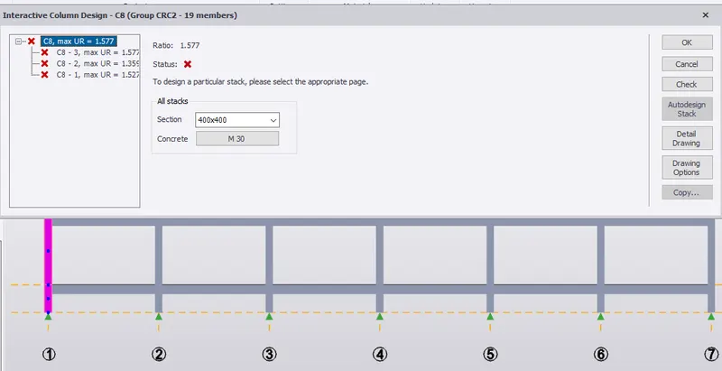
- Change the member section to 650mmx650mm.
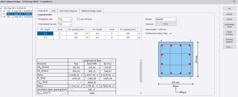
- Select stack 1 of C8 column as shown utillity ratio is 0.917
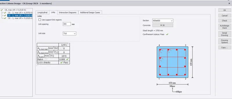
- Provide Torsional bars of 32 mm diameter for both principle and intermediate bar and also T10 bars as link bars which pass the design criteria.
- Select column 9 for interactive design
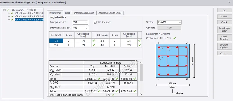
- Change the column section size to 650mm x 650mm
- Select stack 1 provide the bar size to T32 for both prinple and intermediate bars and T10 for link bars.
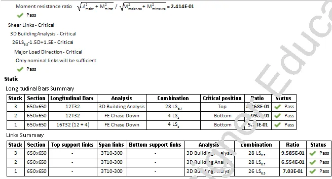
- Therefore, UR for stack 1,2 and 3 are 0.83,0.612 abd 0.91
- Select column C13 for interacitve design.
- Change the column section size to 650mm x 650mm
- Select stack 1, Provide the bar size to T32 for both principle and intermediate bars and T10 for link bars
- Therefore, UR for stack 1,2 and 3 are 0.73,0.66 and 0.98.
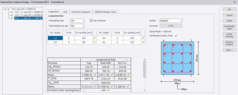
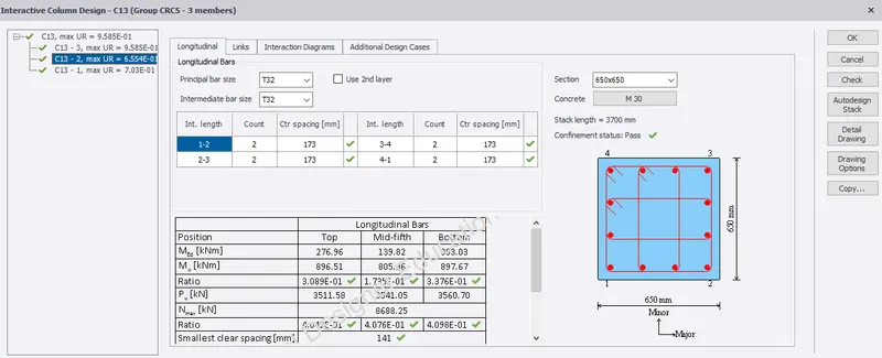
- Similary, Check interactive design for rest of the column in the structure.
(iv) Foundation Design
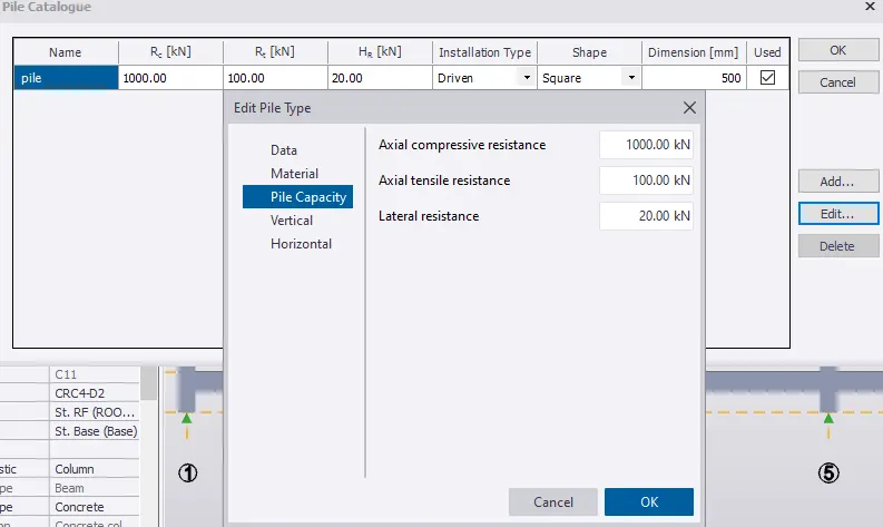
- Go to base floor, set pille type in catalogue.
- Edit data, materials and pile capactiy for piles.
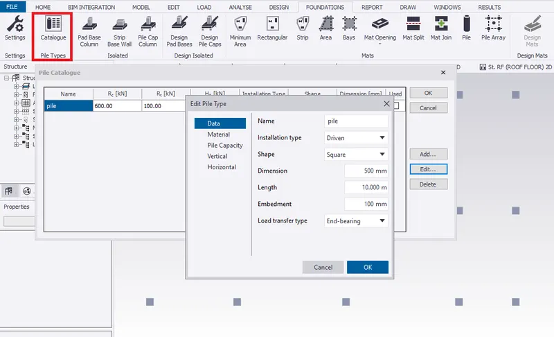
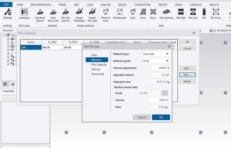
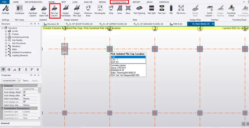
- Selected isolated pile cap column
- Pick the location to created column isolated pile cap position.
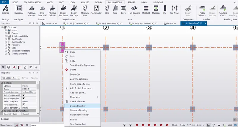
- Select to design the member.
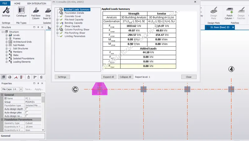
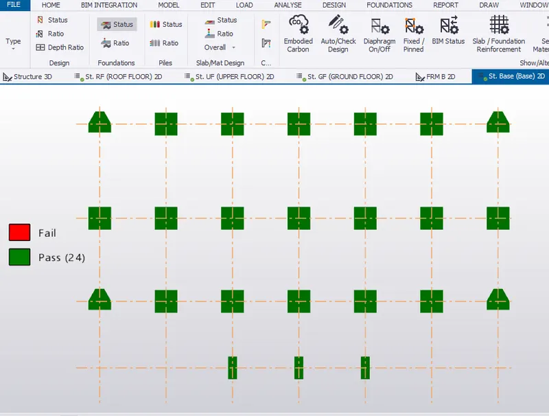
- In reivew view, check the status of the pile cap.
Report Generation
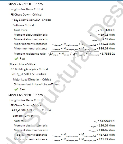
- Select a column to generate report for the member.
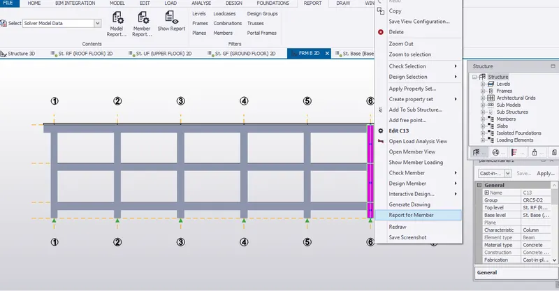
- Report for the particular column is generated with cross section.
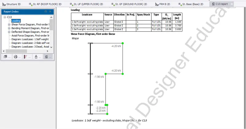
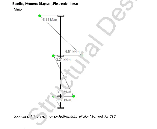
- Select Member report to include loading, shear frce bending moment, deflection and axial force diagram along with design calculation and summary.
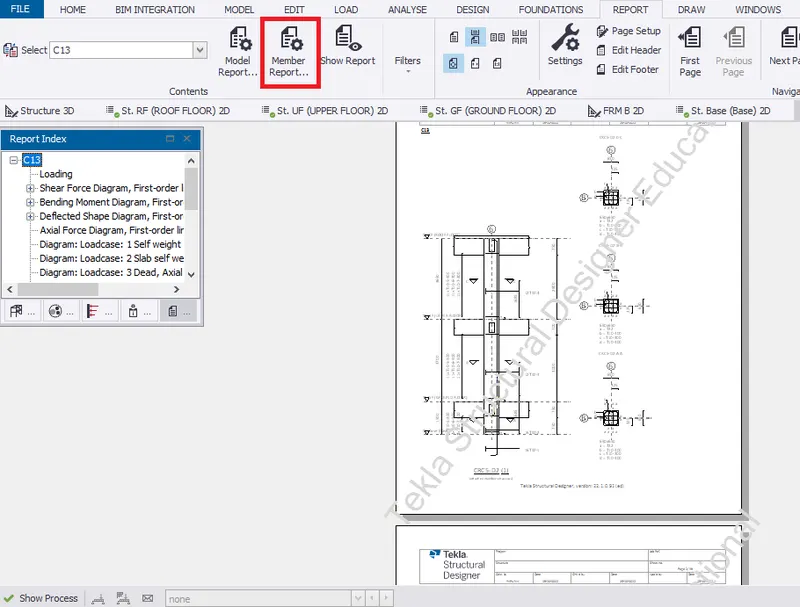
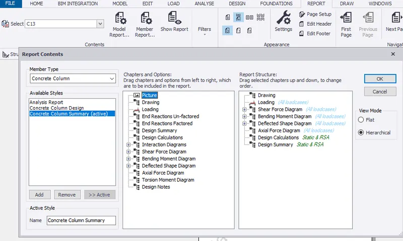
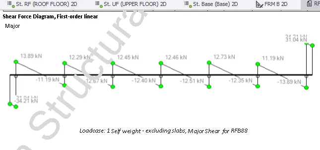
- Report for loading and shear force diagram.
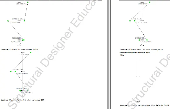
- Bending moment diagram for both major and minor at different loadcases.
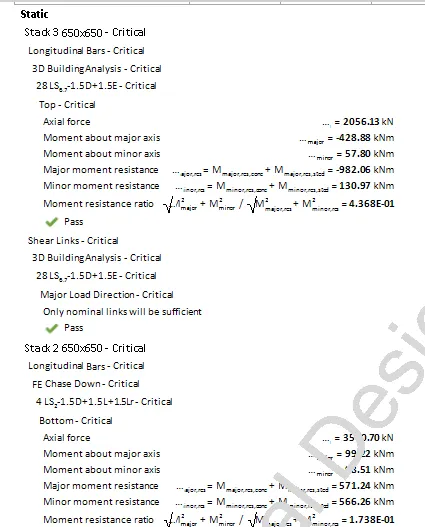
- Design Calculation and summary are shown below.
Concrte Beam Report
- To generate report for RC beam, select Report for Member.
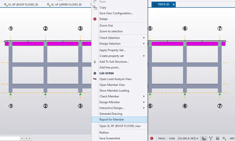
- Therfore, report for the beam is generated.
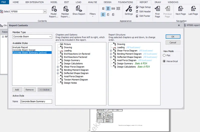
- Select Member report to edit the contents of the beam report.
- T create report, drag selected chapthers under structre which includes drawings, loading, shear force, bending moment, defection and axial force along with design calulation and summary. Click OK.
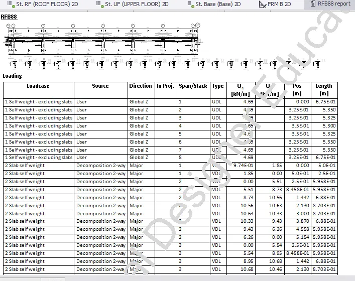
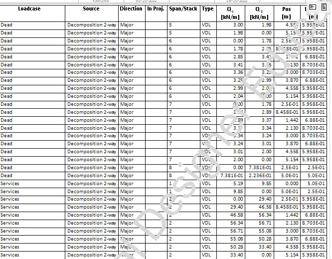
- Shear force diagram in 1st order linear for different load cases is shown.
- Design summary for roof beam (RFB88-12) is generated.
Foundation Report
- Go to base floor, To generate report for RC pile cap, select Report for member
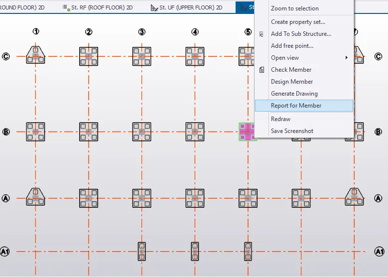
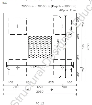
- Drawing of pile cap PC 8 is generated
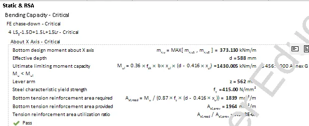
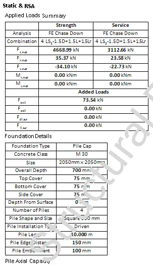
- Design calculation and summary for pile cap are generated.
Layers settings and generate drawings
- Go to draw in tab window.
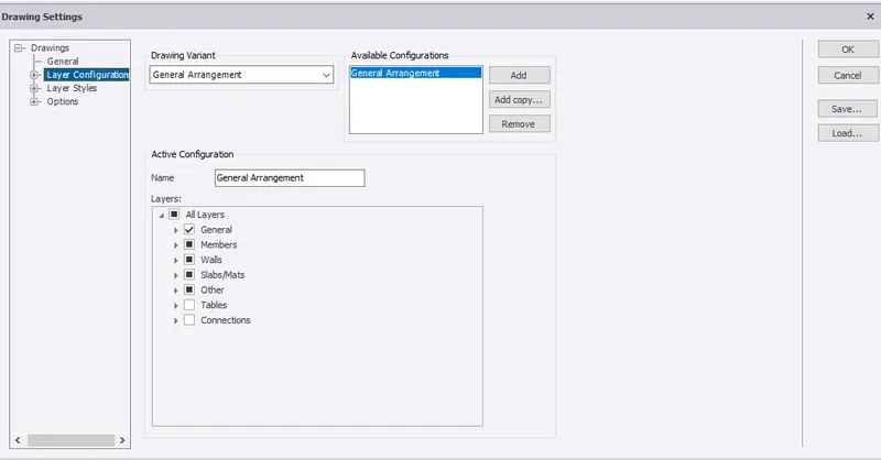
- Select draing settings to set layers for the model so as to generate plan drawing
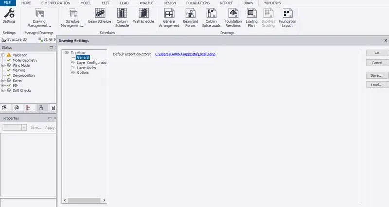
- Select layer configuration to modify the drawing for beams and columns.
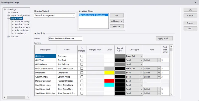
- Layer styles can be modified in drawing variant.
- Select planar drawing from layar styles to change colour. Click ok.
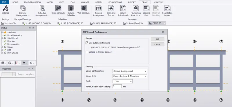
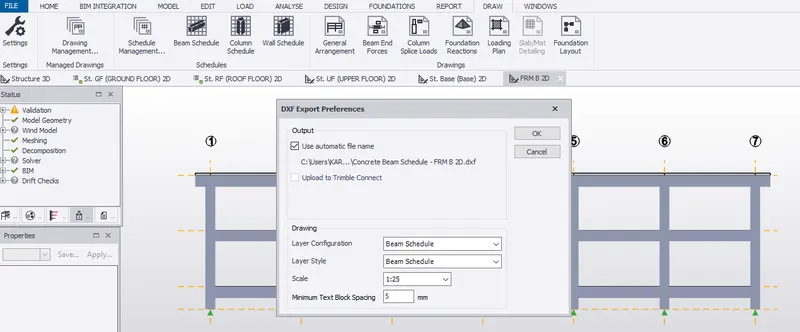
- Go to frame B in scene view
- Select general arrangement from ribbon tab to create and save drawings in 2D view.
- Select beam schedule from ribbon tab to create and save beam reinforcement details in 2D view.
RESULT: Hence, develooped general arrangement for the office building.Also, analyzied and designed the building as per Is standar code in TEKLA STRUCTURAL DESIGNER from the attached.With the above steps, we can design and model the structure as per the given plan. We can add loads (Dead, live, wind and seismic ) to the structure add analyze the structure.Also, generate report of ech member and exteracted drawings ffor structural plans, beam reinforcement details from the software.