Project 2_Analyze and Design the RC office building as per IS standard code in TEKLA STRUCTURAL DESIGNER
Ans 1:- Aim:- To model Rc structure analyse and design the model elements as per IS codal provisions
PROCEDURE:-
- B Open A New Tekla template in Tekla
Go to settings from home tab 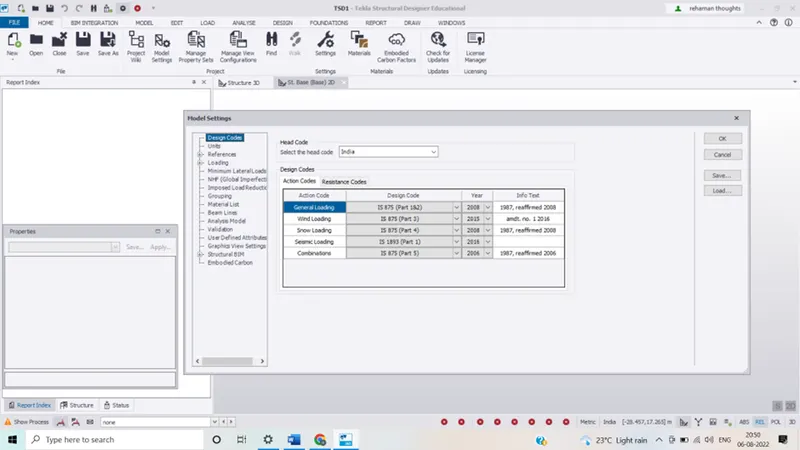
- Assign the design codes and units to be considered in the model
- Define the structural default setting
- Click on ok
Step 1:- to define the construction levels
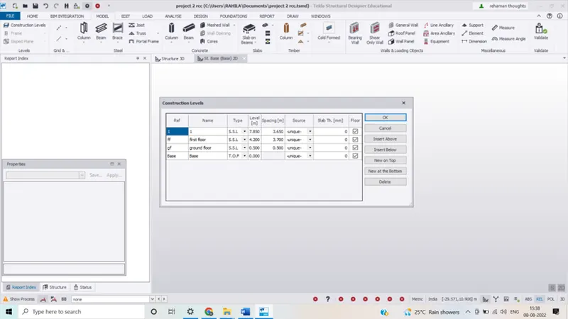
- Click on the construction levels from the model toolbar
- Then add the levels in the dialoge with a given spacing
- Click on ok
-
Step 2:- to draw horizontal and vertical grids
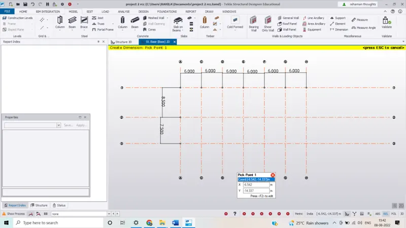
- Click on the the grids icon from the model toolbar
- Specify the first point and drag to draw the first grids
- Then select on the parallel quick grids to draw the other grids lines with a given spacing
- Similarly draw the vertical grids also
Step 2:- to draw horizontal and vertical grids
- Click on the the grids icon from the model toolbar
- Specify the first point and drag to draw the first grids
- Then select on the parallel quick grids to draw the other grids lines with a given spacing
- Similarly draw the vertical grids also
-
Step 3:-
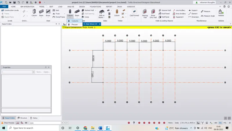
To assign the model elements like columns, beams and slabs
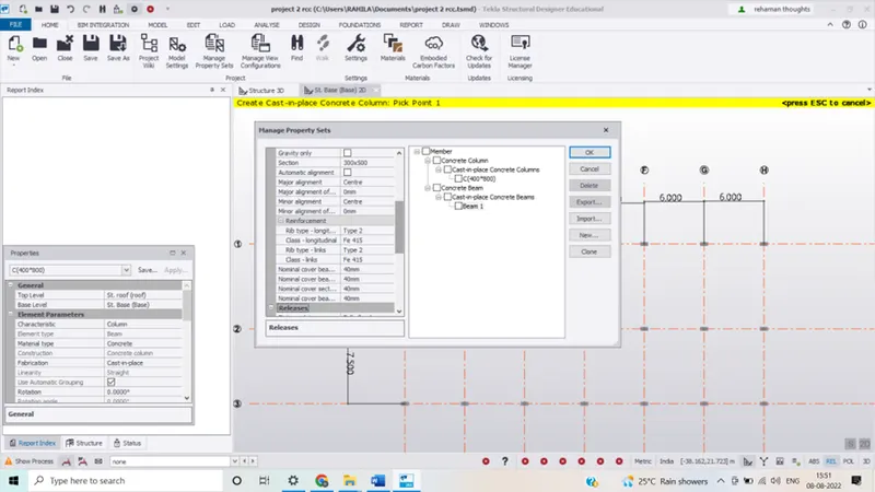
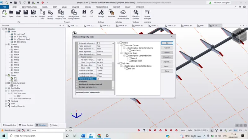
- Go to mange property sets from the home tab
- Click on new then members and concrete column
- Then define the size of the column and grade of concrete
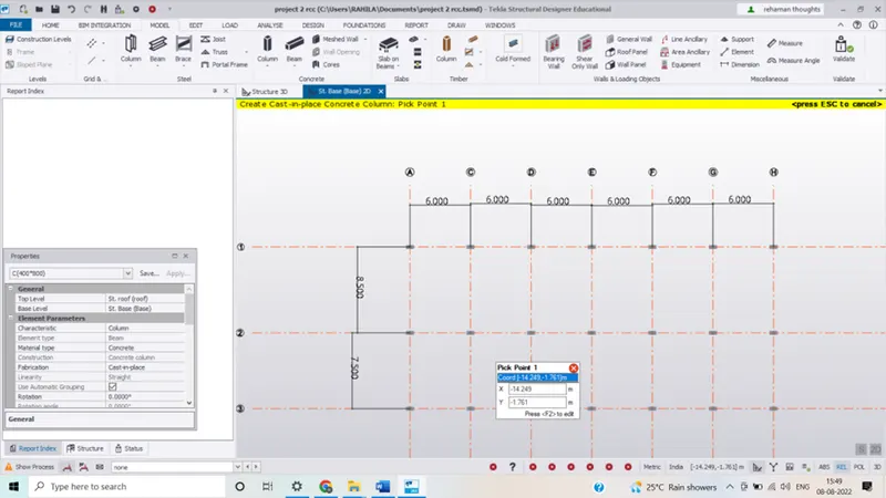
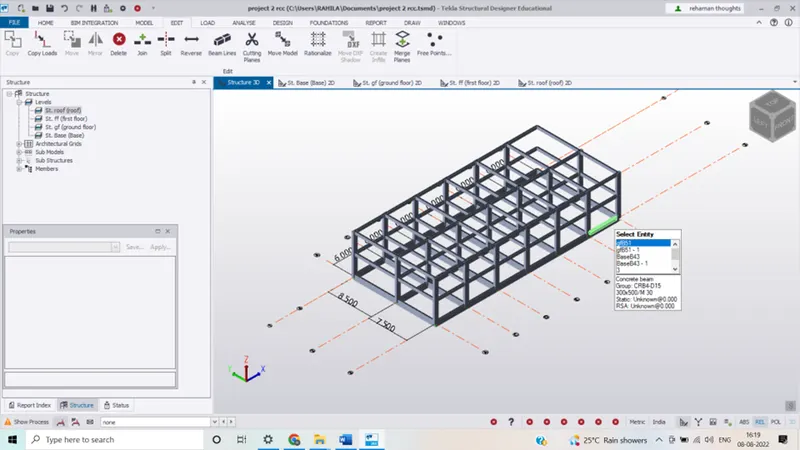
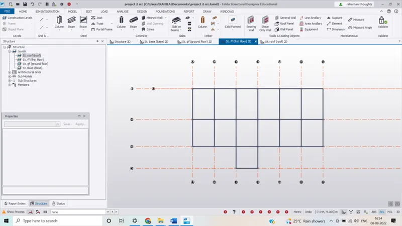 Now define the properties of slab and assign slab panels to the model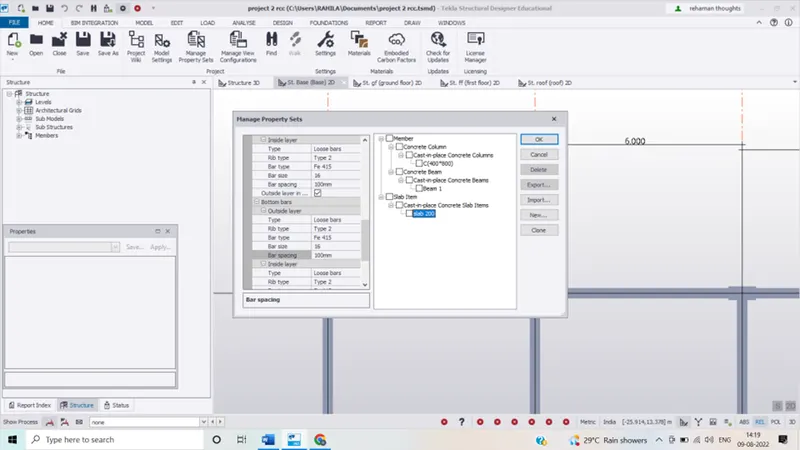
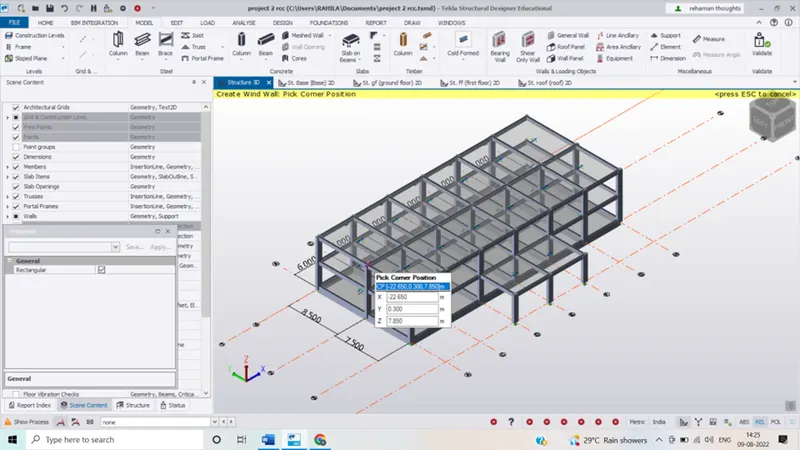
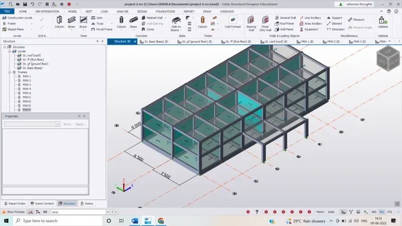
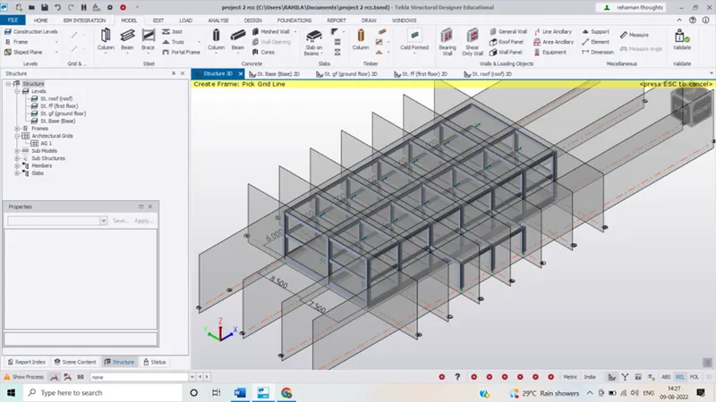 Crate frames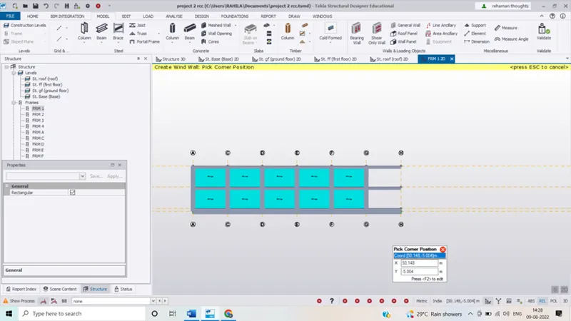
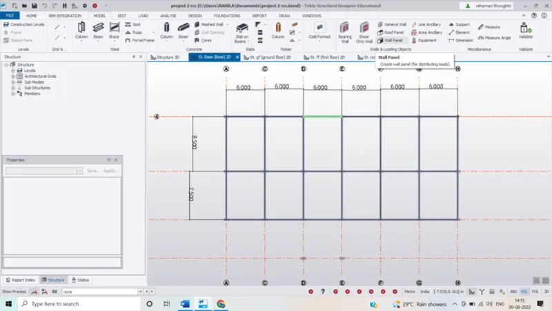
- To addd wall panels to the model
- Select the wall panels from the tab
- Then assign them to the model
Ste[p 4:-
To model the staircase
- Firstly switch of the slab items in scene content
- Select the stair area
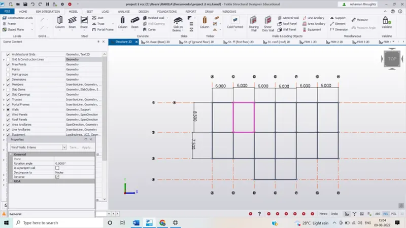
- Right click and add to sub
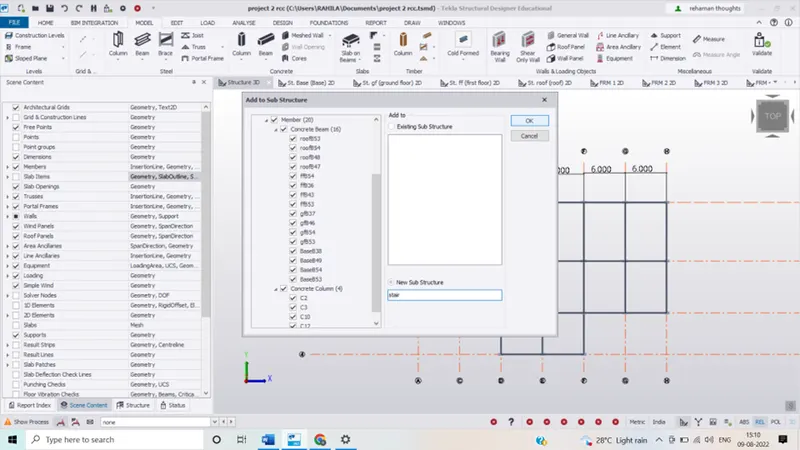 structure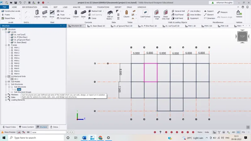
- Double click on stair
- Go to model and then click sloped planes
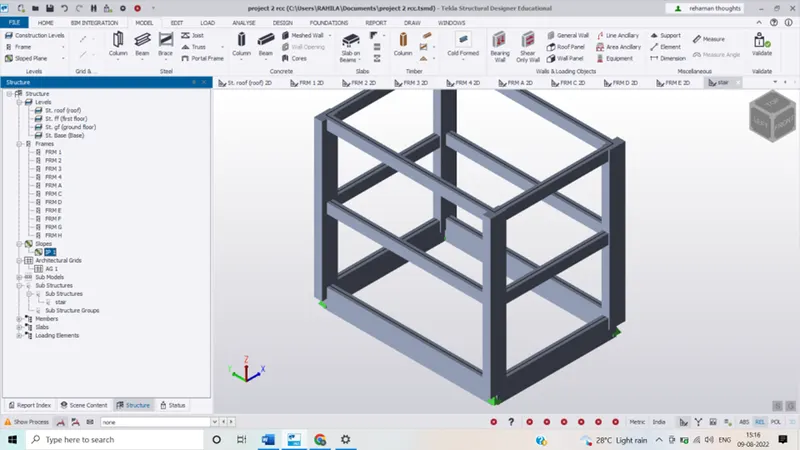
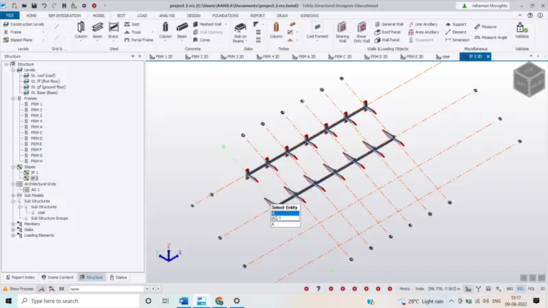
- Define the stringer beams
-
- Draw the stringer beams
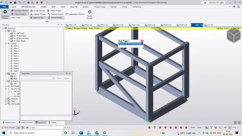 Next we have o offset the grid for that go to plan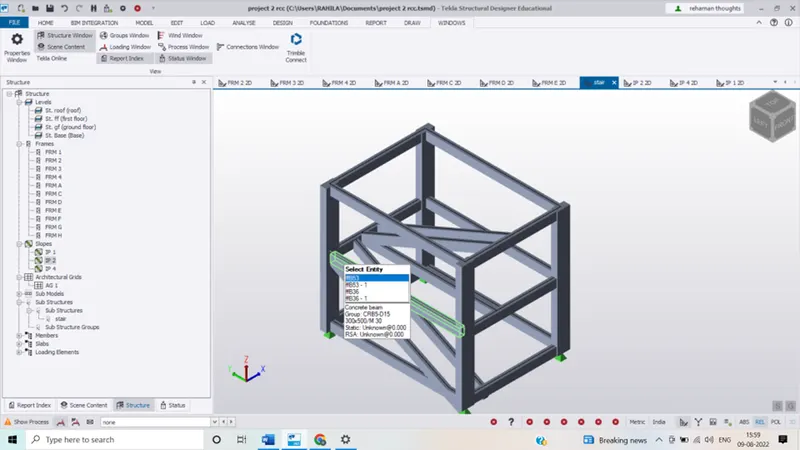
- To draw the staircase firstly we need to create a sloping planes
- To create a slope planes select the slopes from the model tab
- Then click on the nodes to create a sloping planes
- Then click on the beam and add them to a loping planmes
- On which we can place a waist slab
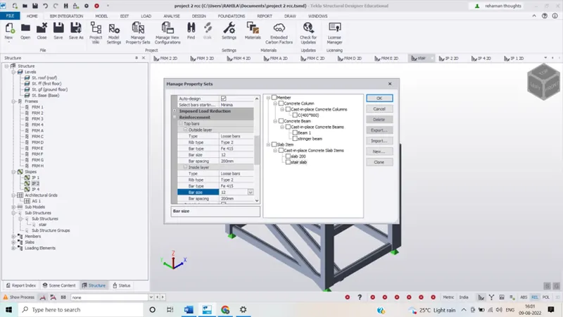
- After defining the stair slab model the slab
- Untick the include in diaphragam as sloping slab can not be act as diaphragam
Caclculation of loads
- Self weight of slab is directly taken by Tekla model
- Dead load of floor finishes
- Assume the thickness of floor finish 80 mm
- Unit weight of concrete is 24 kN/m^3
- Dead load due to floor finish =0.08*24=1.92jN/m^2
- Brick wall loading
- Assume the unit weight of bricks as 20 kN/m^3
- Thickess of exterior wall =230 mm
- Interior wall thicknesss=150 mm
- Height of the Ff =3.5 m
- Height of second floor=3.7 m
- Brick wall load on gf (exterior wall=3.5*0.23*20=16.1kN/m
- Brick wall load on gf interior wall=3.5*0.15*20=10.5kN/m
- Brick wall load on ff (exterior wall=3.7*0.23*20=17.02kN/m
- Brick wall load on ff (interior wall=3.7*0.15*20=11.N/m
- Roof loading is assumed to be 1.5 kN/m^2
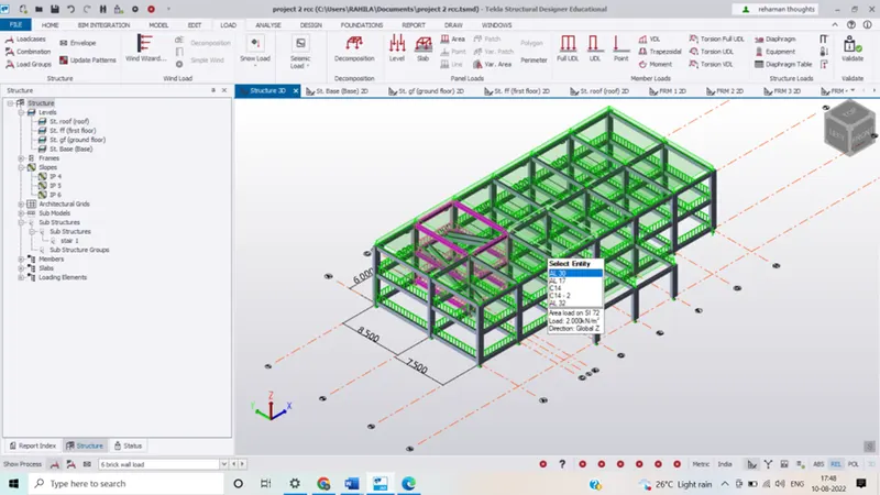
- Floor finish load applied on slab panels
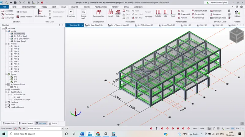
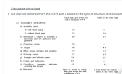
Calculation of live loads
- Live loads are calculated as per is 875 part 2
Step :- Wind load application
- For wind load application first we have to create the wall panels
- Wind speed-50 m/s^2
Terrain category-2
Life span-50 years
Class of structure -50 years
Dimensions of the building
Horizontal dimension-36 m
Lesser horizontal dimension-16m
Height of the building-8.35 m
Ratio of wall and roof coefficient
Wall-l/W=2.25
Wall h/w=0.52
Roof h/w=0.52
Topography factor, k3-1
Risk coefficient(50 years)
Upto 10 m height terrain factor k2=1
Importance factor for cyclonic-k4-1
Designed wind speed v2=vb*k1*k2*k3*k4
=39*1*1*1*1==39m/s
Designed wind pressure pz=0.6Vz^2/1000
=39^2*0.6/1000=912.6N/m^2
Internal pressure coefficient=0.5(20% opening as per clause 6.2.3.3)
Internal pressure coeffiecient=0.5
C=+0.7
-0.3
A=0.7
D—0.1
wind direction and load calculation
Applied in global x direction
wind direction along +X direction (FACE C)
.+cpi
.-Cpi
height of the building
8.35
8.35
External pressure coefficient Cpe
0.7
0.7
internal pressure coefficient Cpi
0.5
-0.5
Net Pressure coefficient Cp=Cpe-Cpi
0.2
1.2
Design wind pressure Pz
0.9
0.9
wind load on wall (cp*pz)kN/m^2
0.18
1.08
wind direction along +X direction (FACE D)
.+cpi
.-Cpi
height of the building
8.35
8.35
External pressure coefficient Cpe
-0.1
-0.1
internal pressure coefficient Cpi
0.5
-0.5
Net Pressure coefficient Cp=Cpe-Cpi
-0.6
0.4
Design wind pressure Pz
0.9
0.9
wind load on wall (cp*pz)kN/m^2
-0.54
0.36
wind direction along +X direction (FACE B)
.+cpi
.-Cpi
height of the building
8.35
8.35
External pressure coefficient Cpe
-0.5
-0.5
internal pressure coefficient Cpi
0.5
-0.5
Net Pressure coefficient Cp=Cpe-Cpi
-1
0
Design wind pressure Pz
0.9
0.9
wind load on wall (cp*pz)kN/m^2
-0.9
0
wind direction along +X direction (FACE A)
.+cpi
6.24
height of the building
8.35
8.35
External pressure coefficient Cpe
-0.5
-0.5
internal pressure coefficient Cpi
0.5
-0.5
Net Pressure coefficient Cp=Cpe-Cpi
-1
0
0.9
0.9
-0.9
0
Design wind pressure Pz
0.991875
-0.99188
wind load on wall (cp*pz)kN/m^2
mwind direction and load calculation
Applied in global y direction
wind direction along +y direction (FACE C)
.+cpi
.-Cpi
height of the building
8.35
8.35
External pressure coefficient Cpe
-0.7
-0.7
internal pressure coefficient Cpi
0.5
-0.5
Net Pressure coefficient Cp=Cpe-Cpi
-1.2
-0.2
Design wind pressure Pz
0.9
0.9
wind load on wall (cp*pz)kN/m^2
-1.08
-0.18
wind direction along +Y direction (FACE D)
.+cpi
.-Cpi
height of the building
8.35
8.35
External pressure coefficient Cpe
-0.7
-0.7
internal pressure coefficient Cpi
0.5
-0.5
Net Pressure coefficient Cp=Cpe-Cpi
-1.2
-0.2
Design wind pressure Pz
0.9
0.9
wind load on wall (cp*pz)kN/m^2
-1.08
-0.18
wind direction along +Y direction (FACE B)
.+cpi
.-Cpi
height of the building
8.35
8.35
External pressure coefficient Cpe
-0.3
-0.3
internal pressure coefficient Cpi
0.5
-0.5
Net Pressure coefficient Cp=Cpe-Cpi
-0.8
0.2
Design wind pressure Pz
0.9
0.9
wind load on wall (cp*pz)kN/m^2
-0.72
0.18
wind direction along +Y direction (FACE A)
.+cpi
-cpi
height of the building
8.35
8.35
External pressure coefficient Cpe
0.7
0.7
internal pressure coefficient Cpi
0.5
-0.5
Net Pressure coefficient Cp=Cpe-Cpi
0.2
1.2
0.9
0.9
0.18
1.08
Design wind pressure Pz
wind load on wall (cp*pz)kN/m^2
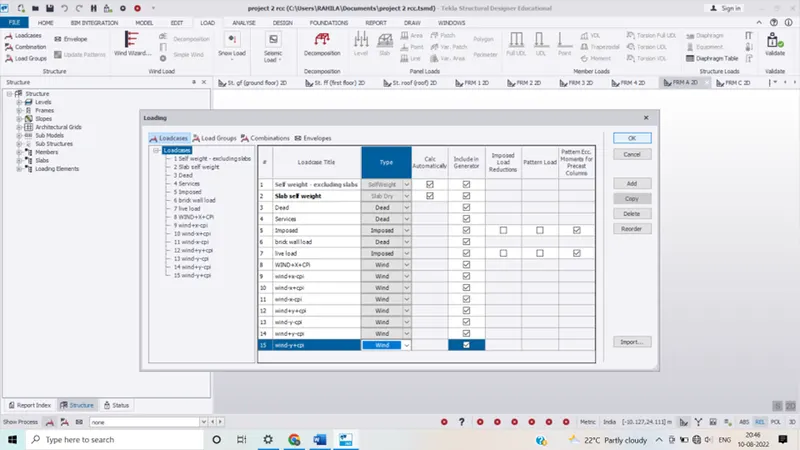
- Select the frames and apply the wind load
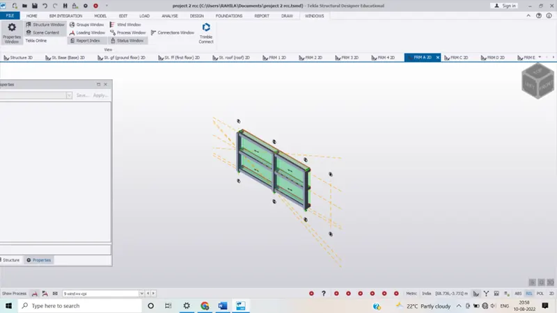
- Similarly apply all the loads
- By creating wall panes and add the loads
- Wind+x+cpi
- Wind-x+cpi
- Wind-y-cpi
- Wind+y-cpi
- Wind+x+cpi
Seismic load applications:-
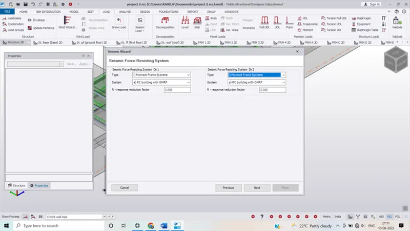
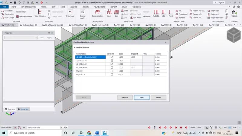
- Apply the seismic load by clicking to seismic wizard option under load tab
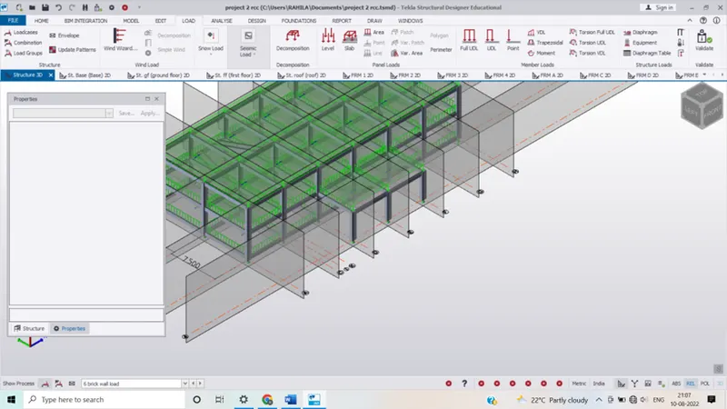
- Enter the required values for seismic load calculation
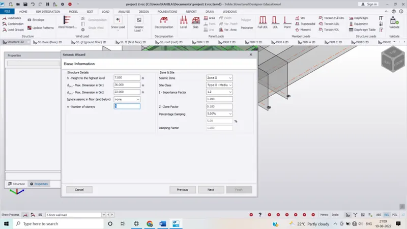
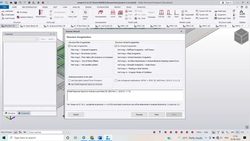
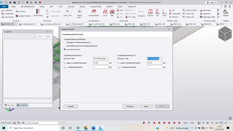
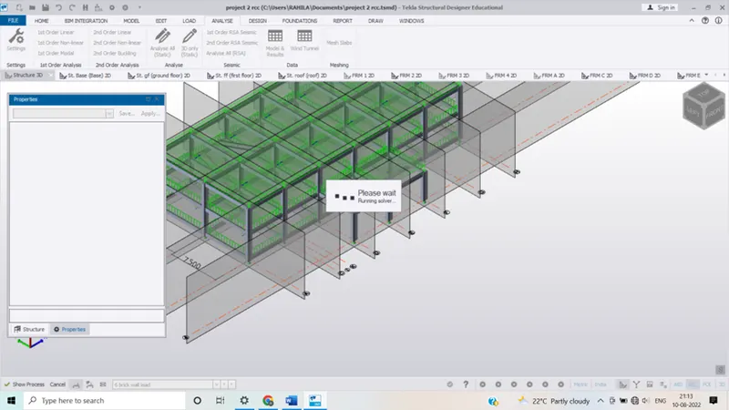
- Analyse the structure by selecting 1st order linear equation
 Check the axial load calulation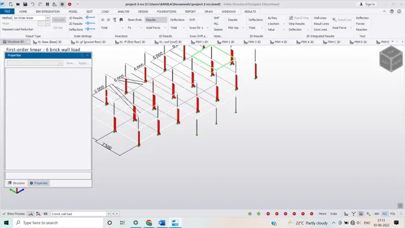
- Design of members
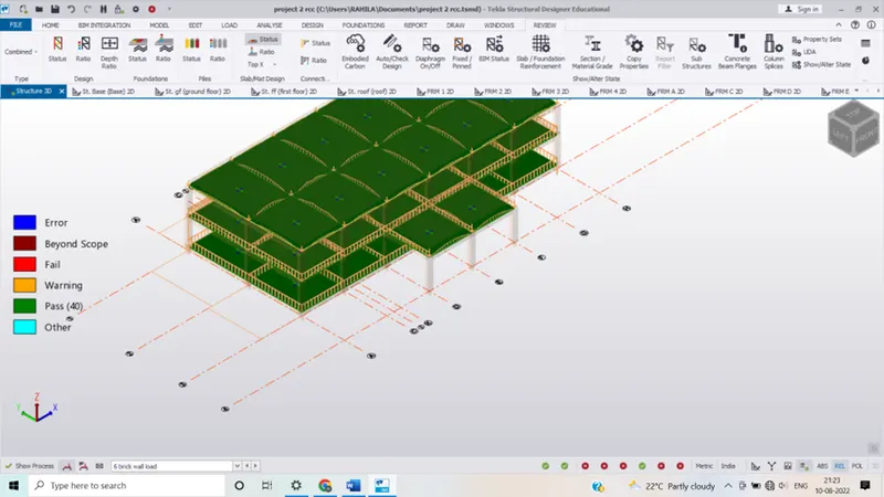
- Design of slab go to design and select analsys and design
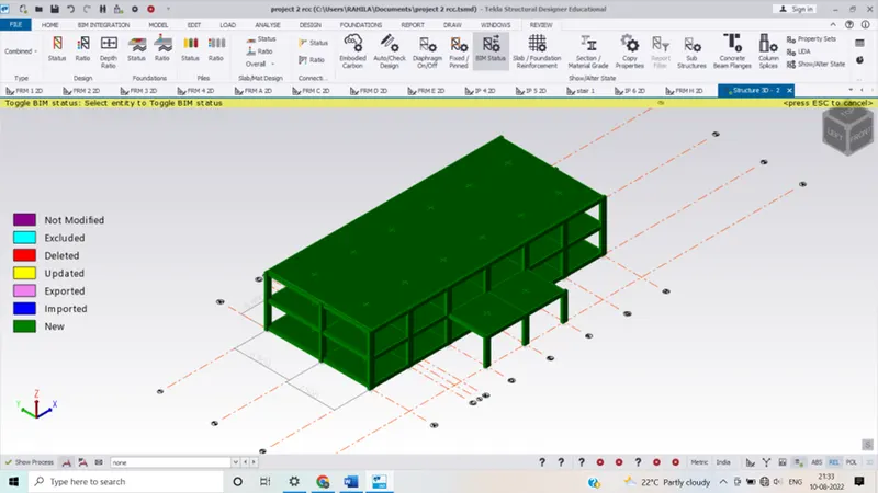
- we can see that all the slabs are passing
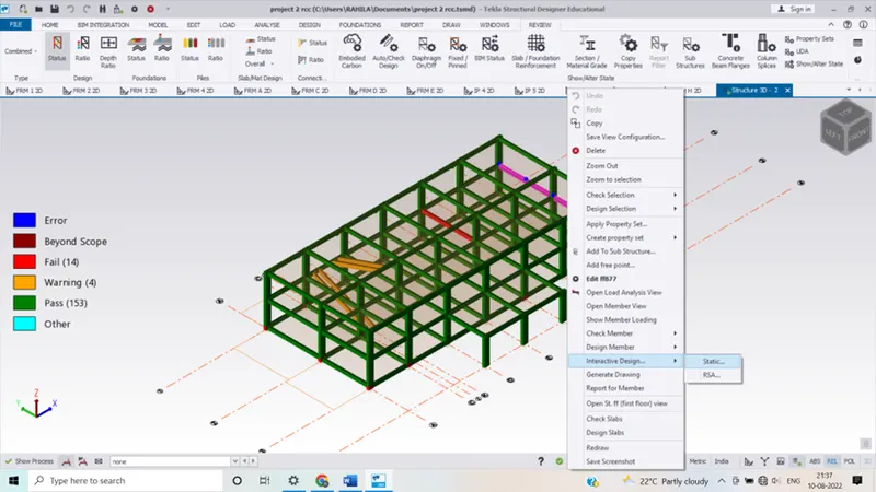
- Right click and select the interactive design
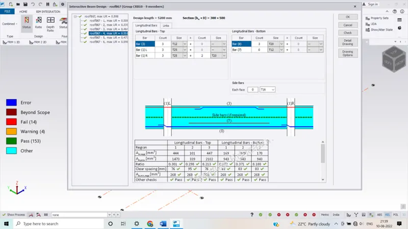 Similarly select the columns and right click and select interactive designs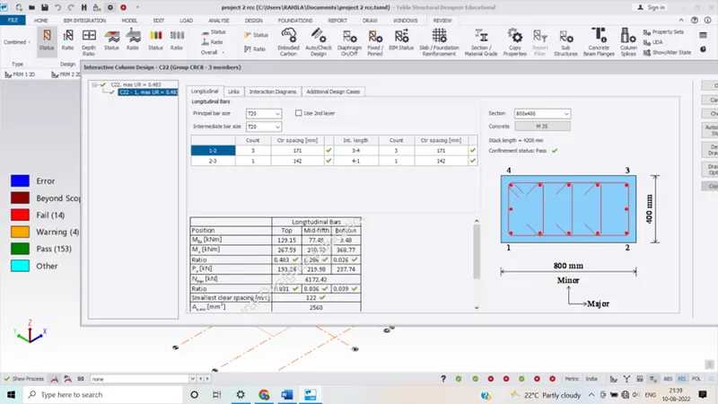
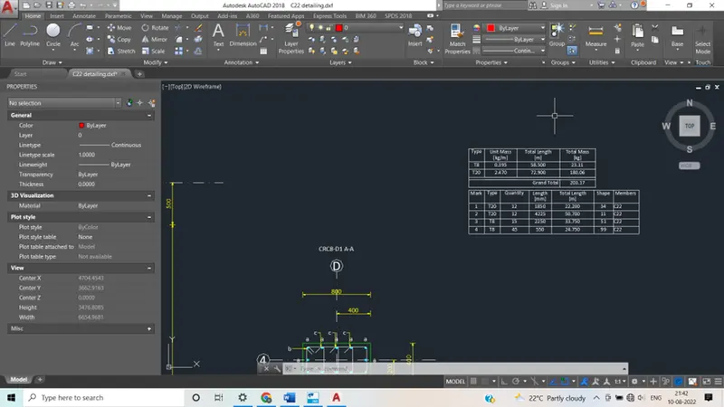
- Similarly we can get repotts and design for beams
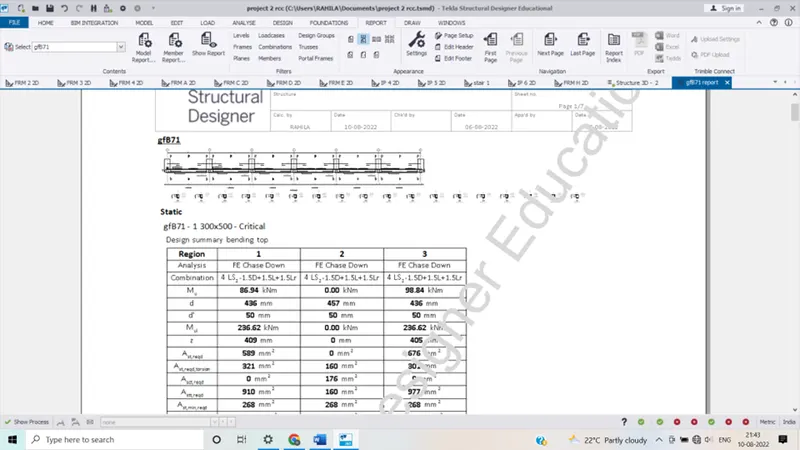 Click on report tab inorder to get the report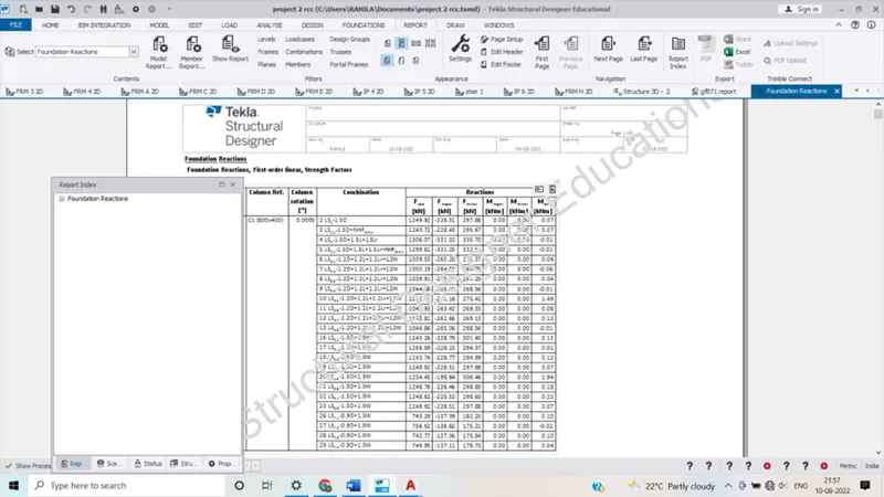
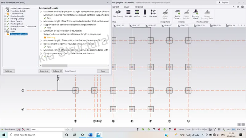
- Hence we have designed the building.
- Live loads are calculated as per is 875 part 2