Project 2_Analyze and Design the RC office building as per IS standard code in TEKLA STRUCTURAL DESIGNER
Aim:-
To model the RC structure analyze and design the model elements as per the IS codal provisions
procedure:
Open a new template in tekla and then go to settings from the home tab
Assign the design codes and units to be considered in the model
Define the structural default settings
Click on ok
step 1:-
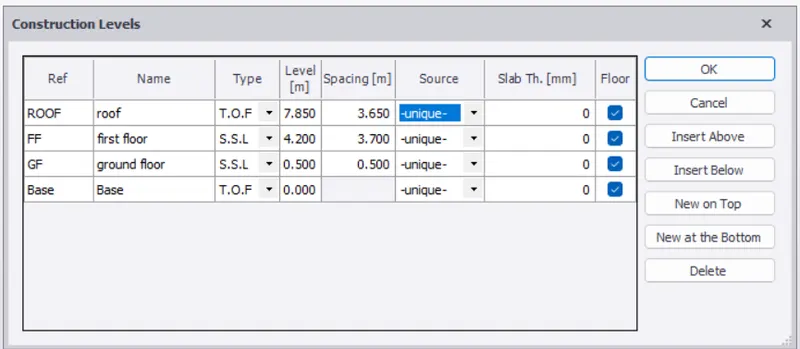
To define the construction levels
Click on the construction levels from the model toolbar
Then add the levels in the dialogue box witha a given spacing
Click on ok
Step 2-
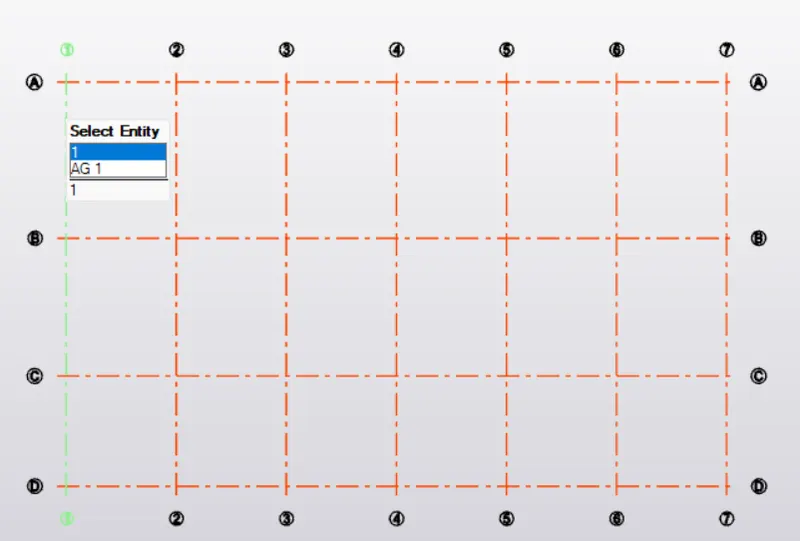
To draw horizontal and vertical grids
Click on the grids icoin from the model toolbar
Specify the first point and drag to draw the first grids
Then select on the parallel quick grids to draw the other grid lines with a given spacings
Similarly draw the vertical grids also
step 3:-
To assign the model elements like columns, beams and slabs
Go to manage property sets from the home tab
Click on new members > concrete column
Then define the size of the column and grade of concrete
Click on ok
Now go to model tab and select on the concrete column icon
Select the section from the properties browser
Click on the grid intersections to place the column
Similarly add the properties of the beams and slab using manage property sets and assign them to the model
Now define the properties of the slab and assign slab panels to the model
To add wall panels to the model
Select the wall panels from the model tab
Then assign them to the model
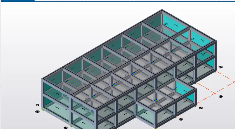
step 4:- Calculation of loads
Calculation of dead loads
Self weight of the slab is directly taken by the tekla model
Dead load of floor finishes
Assume the thickness of the floor finish as 75mm
Unit weight of the concrete is 24 kn/m^3 dead load due to floor finishes= 0.075 x 24 =1.8 kn/m^2
Brick wall loading
Assume the unit weight of the bricks as 20 kn/m^3
Thickness of the exterior wall is 230mm
Thickness of the interior walls is 115mm
Height of the first floor is 3.5m
Height of the second floor is 3.7m
Brick wall load on the ground floor beams(exterior walls) = 3.5x0.23 x 20=16.1 kn/m
Brick wall load on the ground floor beams (interior walls) = 3.5x0.15 x 20=10.5 kn/m
Brick wall load on the first floor
Beams(exterior walls) = 3.7x0.23 x 20-17.02 kn/m
brick wall load on the first floor beams (interior walls) = 3.7x0.15 x 20=11.1 kn/m
Roof loading is assumed as 1.5 kn/m^2 as per IS code provisions
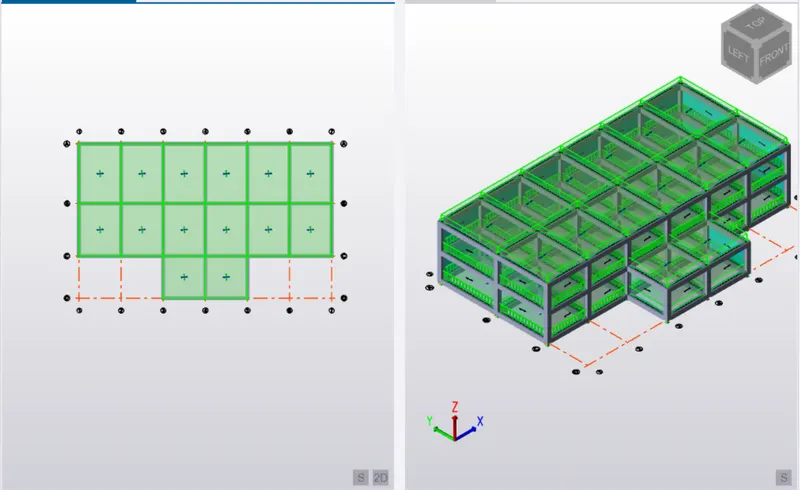
Calculation of live load
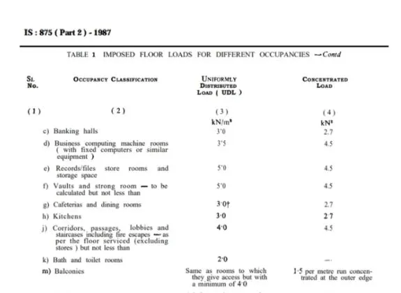
Live load are obtained from the IS 875 part 2 based on the type of structure and occupancy
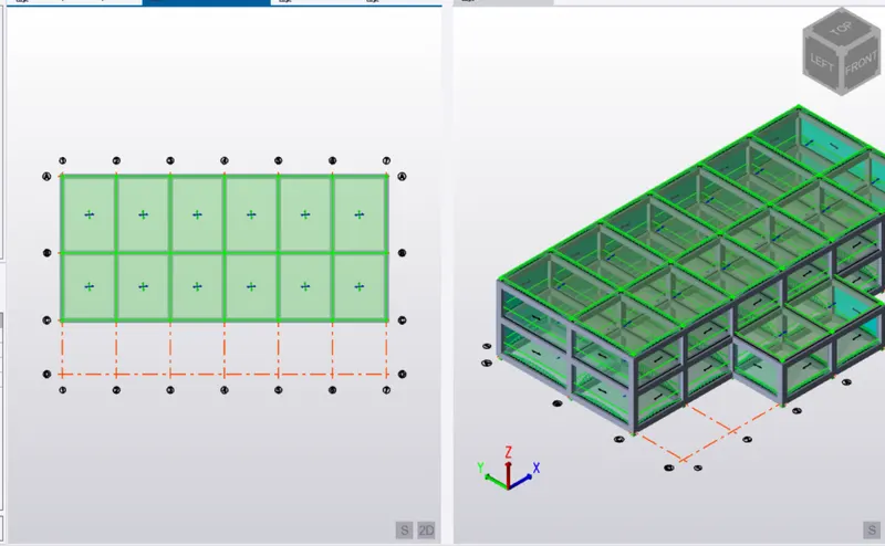
APPLICATION OF LIVE LOAD ON THE SLAB PANELS
Calculation of wind loads
Assume the basic wind speed as 50 m/s
Terrain category as 2
Design life of the structure as 50 years
Assume the structure to be class A
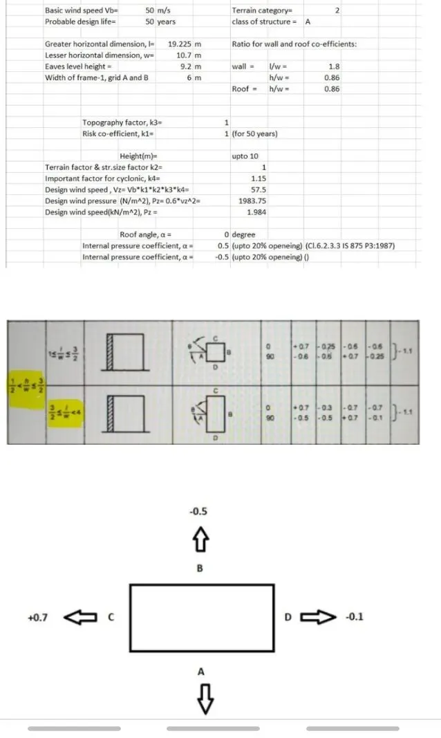
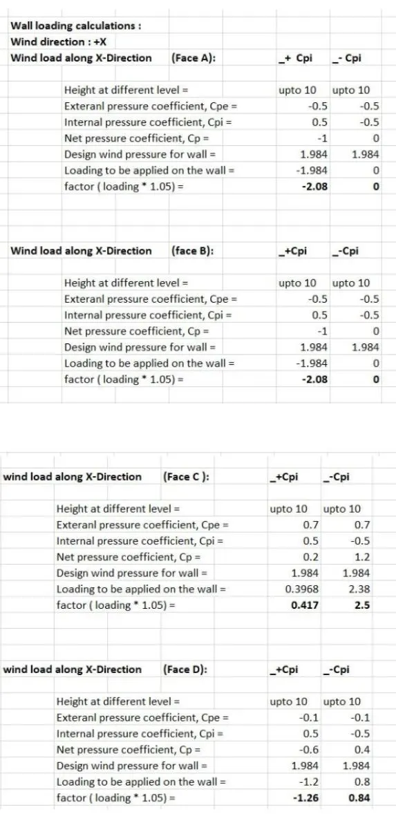
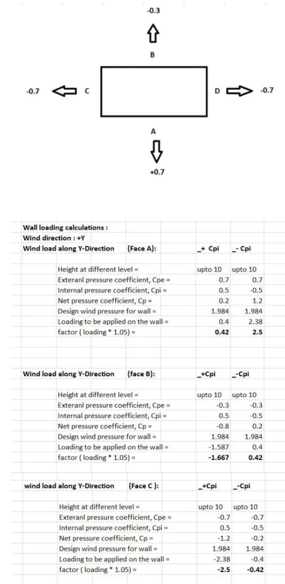
Application of wind loads to the model to define the load cases
Click on loads > load cases and then add the wind load combinations to the dialogue box
Click on ok
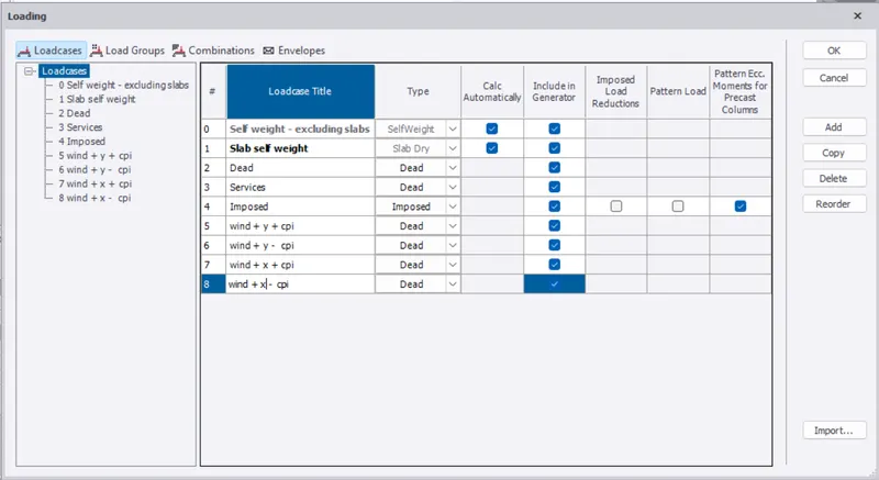
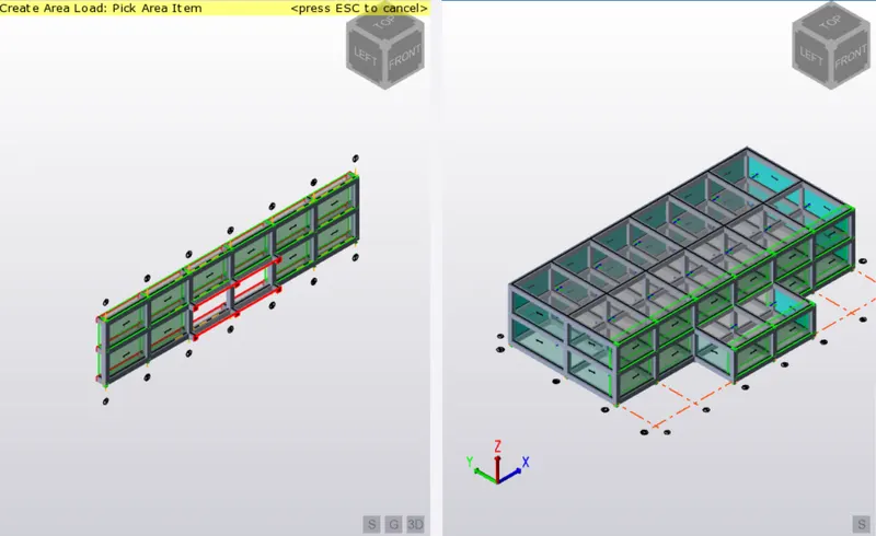
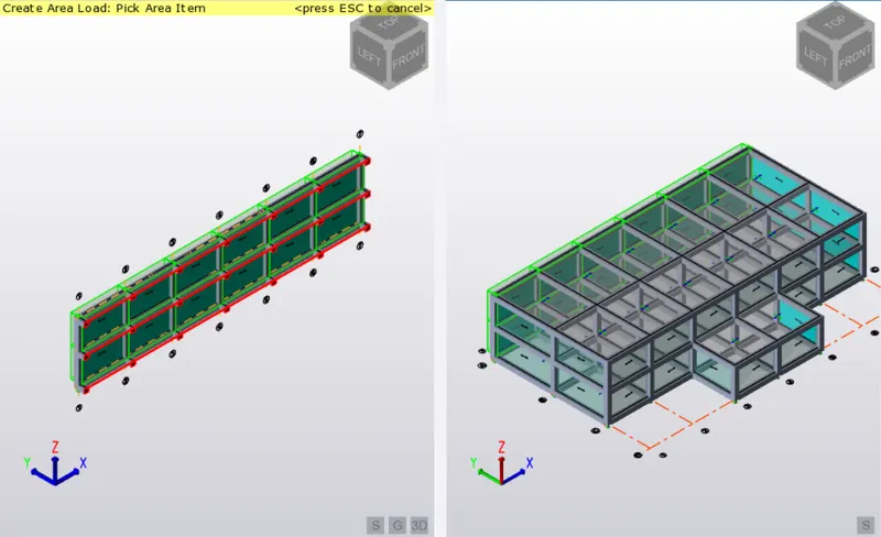
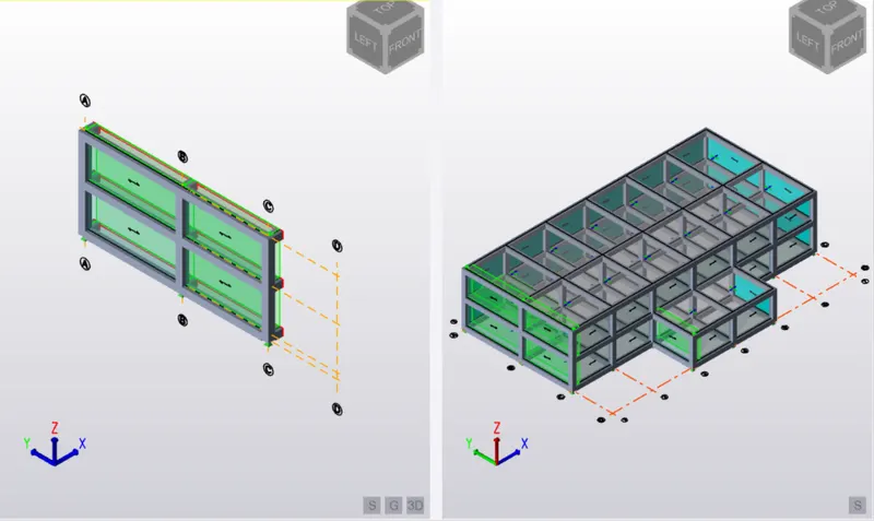
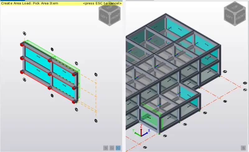
Then we need to create frames to assign the wind loads to the mode
Go to model and click on frames and select on the grid to create frames
Then select the corresponding frame to assign the wind loads
Seismic load
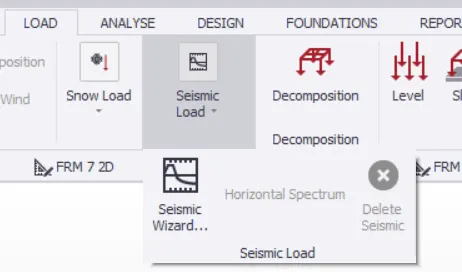
Go
To run the analysis
Firstly check with the modifaction factor
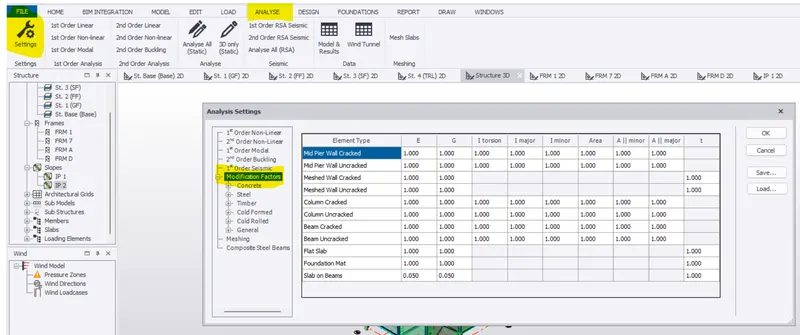
Then click on ist order linear analysis from the analyze tab


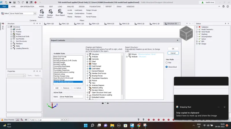
The analysis has been done but the results view doesnot display any of the combinations in my project because of which couldnot upload the images of deformations, shear force and bending moment
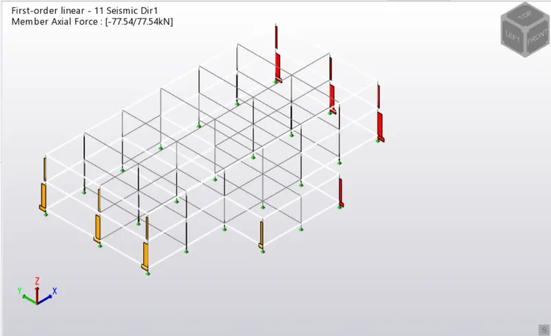
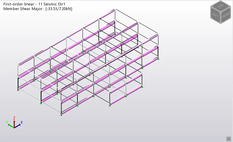
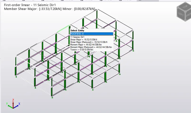
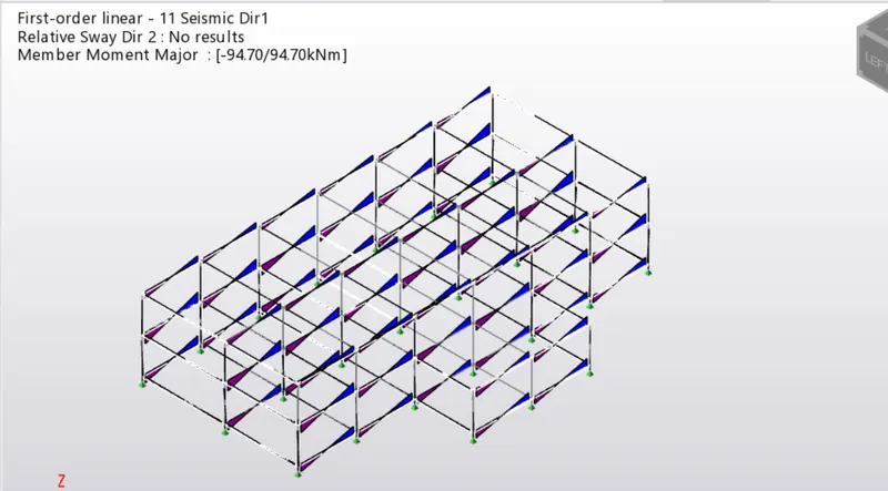
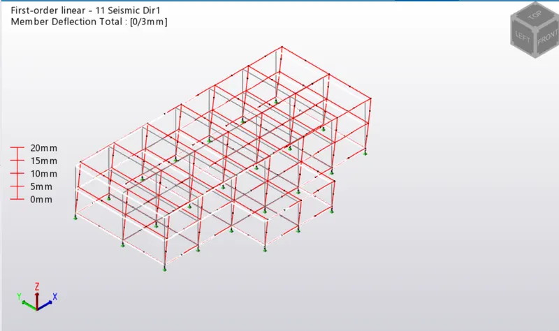
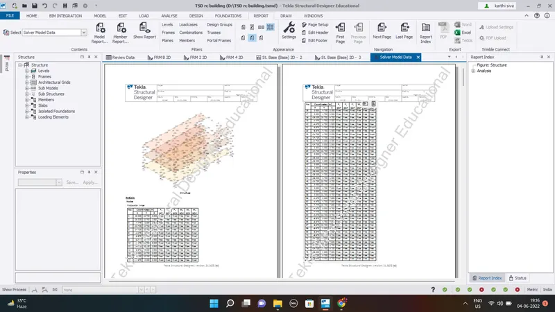
Now we can model the structure by model report