Project 2 Adaptive Cruise Control
Justification of Answer:
Aim of Project: To develop Adaptive Cruise Control logic in MATLAB-Simulink by fulfilling the objectives.
Description:
Requirement 1– Lead Vehicle:
Two inport’s have been created, namely CameraInput_LeadVehicle, & RadarInput_LeadVehicle, now in order to avoid the complexity sensor fusion techniques have been neglected. Now the signals from the two inport’s are fed to the add block, which results in a output signal LeadVehicle_Speed, this signal is connected to an outport having the same name as that of an output signal ( LeadVehicle_Speed) as shown in the figure below.

Requirement 2 – Drive Vehicle
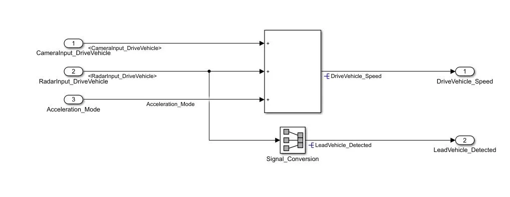
Similar to the Lead vehicle case, Drive Vehicle algorithm also has 2 input signals namely CameraInput_DriveVehicle, RadarInput_DriveVehicle, in addition to that one more signal, Acceleration_Mode will be an input to this subsystem. These three input signals are added to give an output signal, DriveVehicle_Speed. With the help of signal conversion block the input signal RadarInput_DriveVehicle is converted to output signal LeadVehicle_Detected as shown in the below figure. Hence this subsystem has three input signals and two output signals.
Requirement 3 – Adaptive Cruise Control Algorithm:
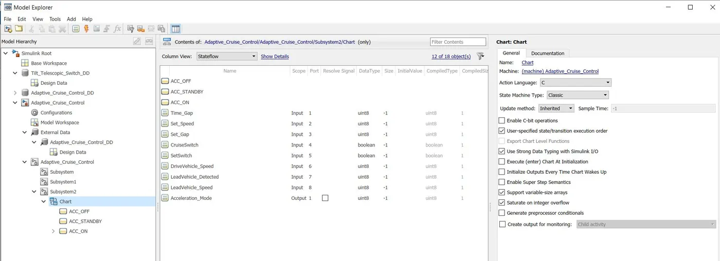
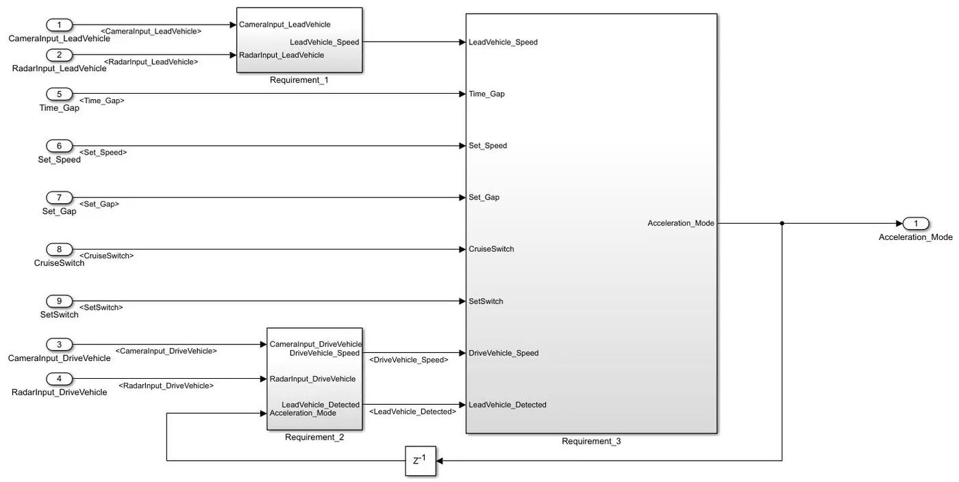
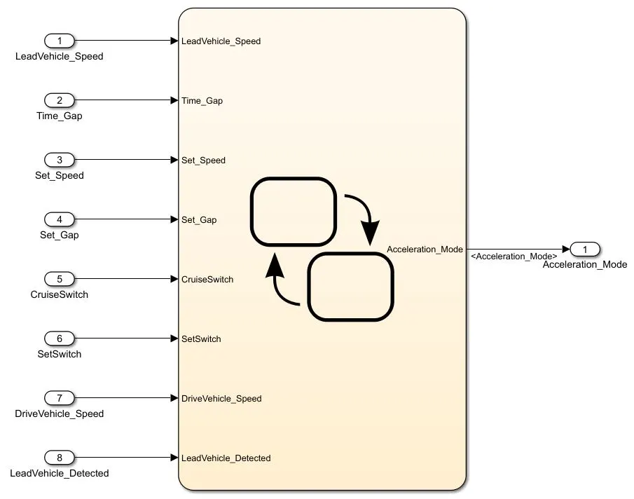
It requires chart block for implementation and mainly has 3 major modes of operation: OFF Mode, STANDBY Mode & ON Mode. The input signals to this Stateflow chart are Time_Gap, Set_Speed, Set_Gap, CruiseSwitch, SetSwitch, DriveVehicle_Speed & LeadVehicle_Detected from requirement-2 is fed back as an input signal into this chart block, additionally LeadVehicle_Speed from requirement-1 is also given as an input signal to the chart. Output from this flow chart is a signal (Signal Name: Acceleration_Mode) which governs the vehicular speed of the drive vehicle which automatically adjusts its speed & velocity to match the lead vehicle. This Output signal is fed back to the Drive Vehicle subsystem (Requirement 2) as a feed back for speed adjustment. The inputs and outputs to the flow chart can be added by clicking modeling>> Model explorer>> chart. The model explorer window is as shown below.
The below figure shows the connectivity of Requirement_1, Requirement_2 subsystems with Requirement_3 subsystem and below that shows the chart figure displaying all the inputs and output.
Requirement 3a – ACC OFF MODE state logic:
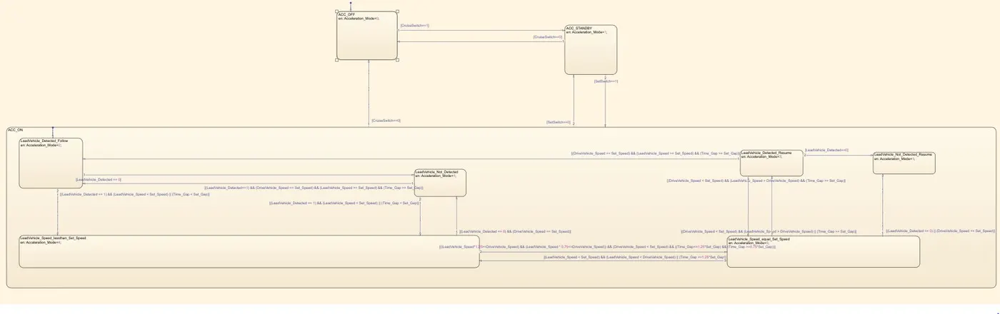
Now by double clicking on the chart, we will enter into the chart, lets first create three states namely ACC_OFF, ACC_STANDBY and ACC_ON, with ACC_OFF being the default state. In ACC_OFF state, Output signal Acceleration_Mode is of value 0, hence this can be entered as en: Acceleration_Mode=0;,where en corresponds to entry. Now the transition to other states is done through CruiseSwitch. If CruiseSwitch is equal to 1, state ACC_STANDBY will get activated. If CruiseSwitch is equal to 0, state ACC_OFF will get activated, from either ACC_ON or ACC_STANDBY. These values can be entered into transition signal by double clicking the transition signal and then selecting condition ([ ]). For example, transition signal with required condition has to be created from ACC_OFF state to ACC_STANDBY state, then first the cursor have to be brought to the boundary of ACC_OFF state, a plus like symbol will appear then we have to left click and drag the signal and release the click at the boundary of ACC_OFF state. By this the signal will be produced. Now double click the transition signal, three options appear, which are  1) Event name/Message name, 2) condition, and 3) Action. Select the condition [ ] and enter CruiseSwitch = 1 inside the [ ], thus completing the transition condition, similarly it can be done for other transition signals and requirements as shown in below figure. Thus completing the Stateflow chart.
Now, the next thing is Data Dictionary creation, go to Modeling >> Link to data dictionary >> New >> Adaptive_Cruise_Control_DD.sldd >> Disable model access to base workspace >> Apply >> Ok.
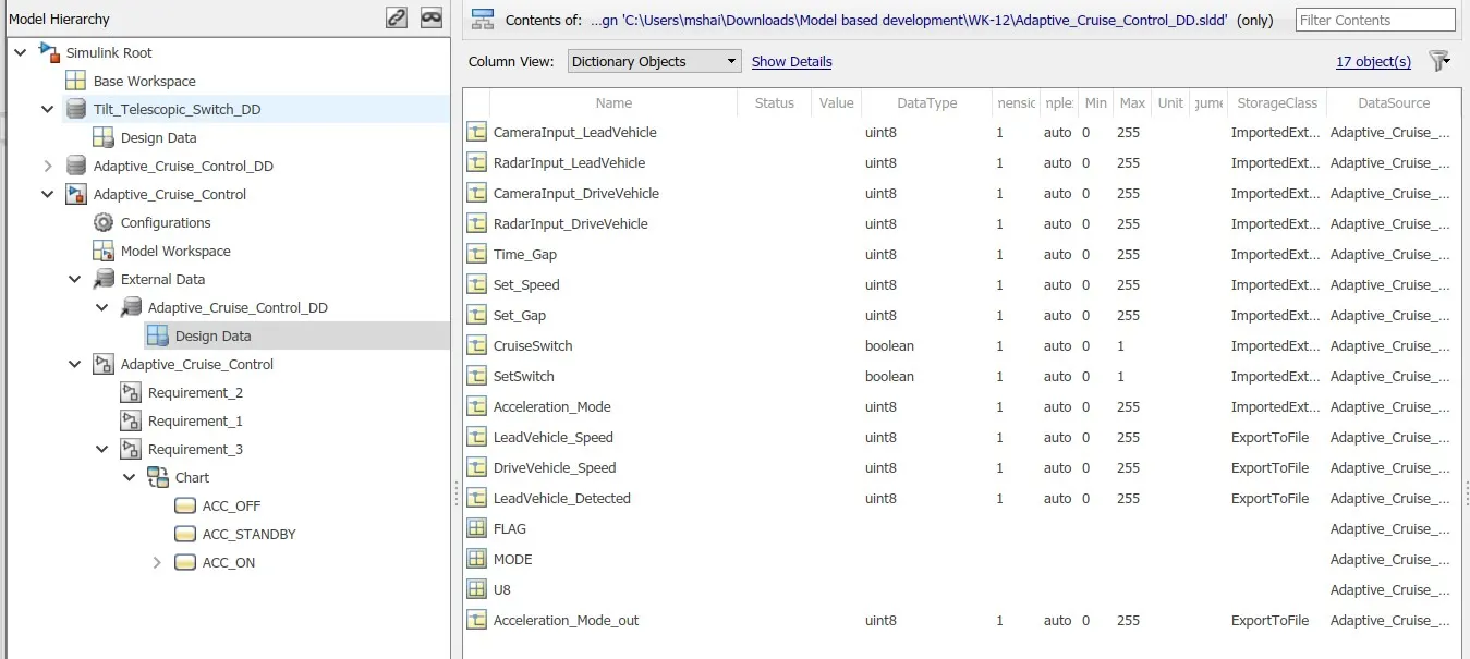
Now in the simulink window click on model data located at left bottom corner, then click on external data >> Design data. Enter the signals as shown below, with Storage class for Input signals: ImportedExtern; Storage class for Output signal: Export to File; Storage class for local signals: localizable; Storage class for calibration signals: Const.
Choose sample time for all signals as 0.01s
Now, the next thing is change of parameter configuration settings, click on Model settings >> solver, change the stop time to 8639, solver type to fixed-step, sover to discrete (no continous states), fixed-step size (fundamental sample time) to 0.01. Similarly other configuration parameters like Diagnostics, model referencing, simulation target, and code generation have to be changed as done in Tilt_Telescopic_Switch model implentation.
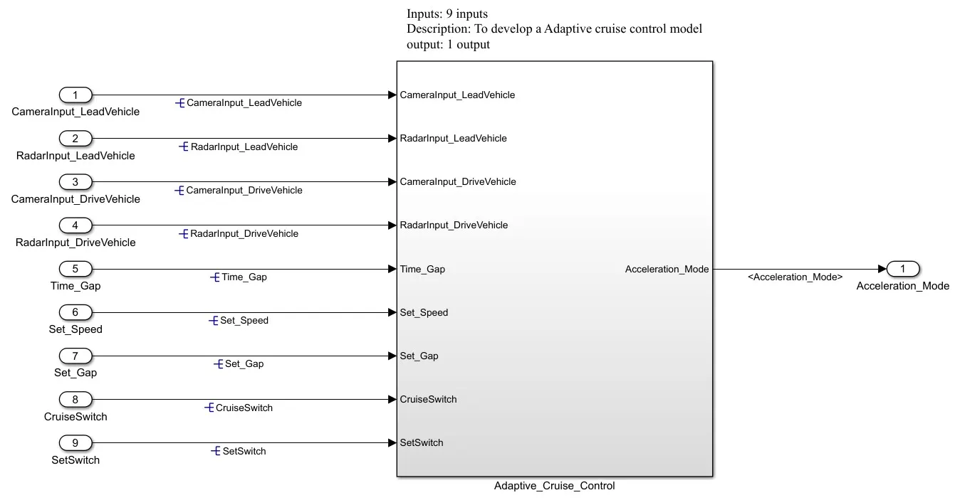
Now, the next thing is resolving the signals, this step is important for code generation, both inports and outports are resolved at there point of origin. Figure below shows the resolved signals respresented by E. The resolving has been done by first selecting the signal, then right click >> properties >> tick signal name must resolve to simulink signal object >> apply >> ok, thus linking the signal to simulink data dictionary.
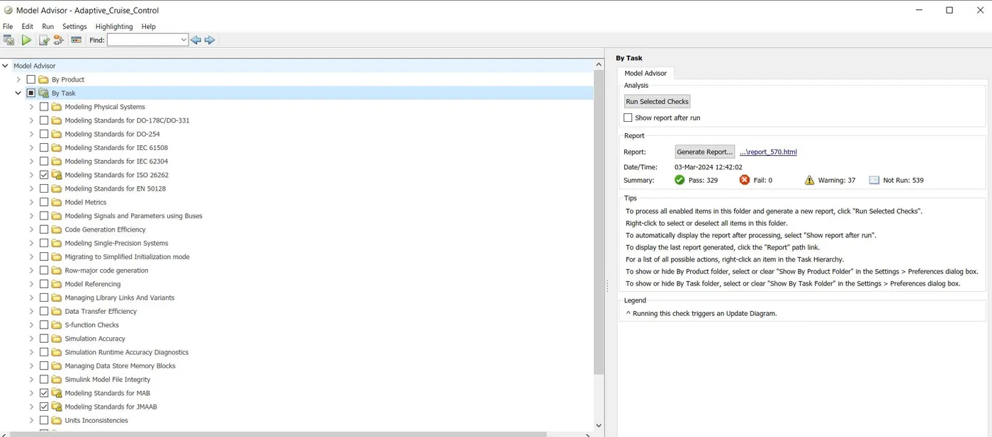
Now, the next step is the Model advisor check, click modeling >> model advisor >> ok >> By Task >> Tick Modeling Standards for ISO 26262, Modeling Standards for MAB, Modeling Standards for JMAAB, Modeling Standards for MISRA C:2012 >> Run selected checks. The general rule is fail has to be zero and try to reduce as much warning as possible by doing the necessary changes. Figure below shows the model advisor window. Report is attached for reference.
Before proceding for code generation, it is always adivisable to run the model to see if it is simulating perfectly. Now, the model have been simulated by pressing the run botton, and it was found that no error was poped-up during simulation and the model simulated perfectly. The final stage, that is the code gneration have been performed by pressing Ctrl+B. The C code have been generated sucessfully.
Result
1) Sucessfully developed Adaptive Cruise Control Logic.
2) All the MBD related processes like Requirement Analysis, Modelling the requirement, SLDD creation, Configuration Parameter changes, resolving the simulink signals, Model Advisor check & Code Generation have been performed except Requirement Tagging & Traceability due to accademic version (License limitation) limatation.
3) C code have been generated sucessfully.
Thank you for your evaluation