Project 1 (Mini Project on Vehicle Direction Detection
Justification of Answer:
Aim of Project: To develop vehicle direction determination logic in MATLAB-Simulink by fulfilling the objectives.
Description:
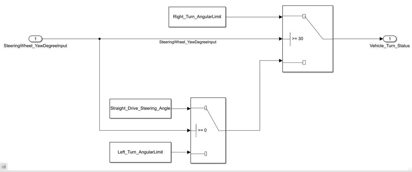
An inport block with name SteeringWheel_YawDegreeInput has been created, now in order to compare with three angular values, one each for left turn, right turn & straight drive two switch blocks have been used. To the top switch condition of >=30 is fed, which means if the input is >=30 then Right_Turn_AngularLimit will be executed as true condition, whose value is 30. Now if the value is less than 30 then the bottom switch gets executed, where it checks for value >=0, if the value is >=0 then Straight_Drive_Steering_Angle will be executed whose value is 0, other wise Left_Turn_AngularLimit will be executed, whose value is -120, and the same will be fed to Vehicle_Turn_Status. This entire logic has been made as a subsystem and named as Requirement-1 as shown in below figure. The Vehicle_Turn_Status output is made local as per the requirement-1. Tagging is not possible because of the academic version but the procedure to tagging is right click on the Requirement-1 subsystem, click on Requirements, then click on link to selection in word and select the Requirement-1 in word and then click on ok. The Requirement-1 subsystem is shown in below figure. The Right_Turn_AngularLimit, Straight_Drive_Steering_Angle and Left_Turn_AngularLimit has been created as parameters in SLDD with the storage class as Const.
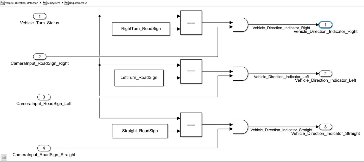
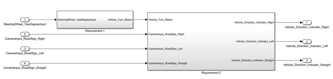
Now for the second requirement, we have two inputs, one from the requirement-1 as local siganl (Vehicle_Turn_Status) and the other from the camera, the camera signal is split into three signals that is CameraInput_RoadSign_Right, CameraInput_RoadSign_Left and CameraInput_RoadSign_Straight. At any point of time only one among the three is going to get activated, that is only one signal among the three will have value 1 and remaining two will have value 0. At first the Vehicle_Turn_Status is compared with RightTurn_RoadSign, LeftTurn_RoadSign and Straight_RoadSign, for example if Vehicle_Turn_Status is found equal to RightTurn_RoadSign, then the output of that purticular relational operator will be one and other relational operators will have 0 value. Now let us assume if all realtional operators have output 1, then this outputs will be compared with camera inputs. If camera detect right sign then CameraInput_RoadSign_Right will be 1 and others will be 0, similarly for Left and Straight signs. It is not possible for a camera to detect all the three or two signs at the same point of time hence only one among the three, that is CameraInput_RoadSign_Right, CameraInput_RoadSign_Left and CameraInput_RoadSign_Straight will have value 1. Let us assume CameraInput_RoadSign_Right has value 1 and output from relational operator is also 1 which are the two inputs to an AND gate, then the ouput from an AND gate will be 1 and hence Vehicle_Direction_Indicator_Right will be having value 1, indicating that vehicle is going to take a right turn, similarly it can be explained in the same way for left and straight signs. Figure below shows the logic of Requirement-2 and underneath the entire logic of the miniproject.
MBD compliant changes, Data Dictionary creation & code generation have been performed.
Storage class for Input signals: ImportedExtern; Storage class for Output signal: Export to File; Storage class for local signals: localizable; Storage class for calibration signals: Const have been set.
Sample time for all signals have been set to 0.01s
Result: MIL testing and code generation has been carried out sucessfully for the Vehicle Direction Detection model.
Thank you for your evaluation