Project 2 Adaptive Cruise Control
Adaptive Cruise Control:
Adaptive cruise control (ACC) is a type of advanced driver-assistance system for road vehicles that automatically adjusts the vehicke speed to maintain a safe distance from vehicles ahead.
Operating Principle:
A radar sensor is usually at the core of the Adaptive Cruise Control (ACC). Installed at the front of the vehicle, the system permanently monitors the road ahead. As long as the road ahead is clear, ACC maintains the speed set by the driver. If the system spots a slower vehicle within its detection range, it gently reduces speed by releasing the accelerator or actively engaging the brake control system. if the vehicle ahead sppeds up or changes lanes, the ACC automatically accelerates to the drivers desired speed.
Standard ACC can be activated from speeds of around 30 km/h (20 mph) upwards and supports the driver, primarily on cross-country journeys or on freeways. The ACC stop & go variant is also active at speeds below 30 km/h (20 mph). It can maintain the set distance to the preceding vehicle even at very low speeds and can decelerate to a complete standstill. If the vehicle has automatic transmission, and the traffic hold-up is only brief, ACC stop & go can set the vehicle in motion once again. When the vehicle remains stopped longer, the driver needs only to reactivate the system, for example by briefly stepping on the gas pedal to return to ACC mode. In this way, ACC stop & go supports the driver even in heavy traffic and traffic jams.
Since ACC is a comfort and convenience system, brake interventions and vehicle acceleration only take place within defined limits. Even with ACC switched ON , it remains the driver’s responsibility to monitor the speed and distance from the vehicle in front.
To increase comfort and safety of this function, a multi purpose camera can be installed in addition to the radar sensor. By this, for instance, ACC can, thanks to the lateral measuring accuracy of the multi purpose camera, detect a vehicle entering the driver’s own lane – either planned or unplanned – much earlier, enabling the system to respond more dynamically. For a better and more robust understanding of the scene, data of the radar sensor and the camera can be merged.
Simulink Model:
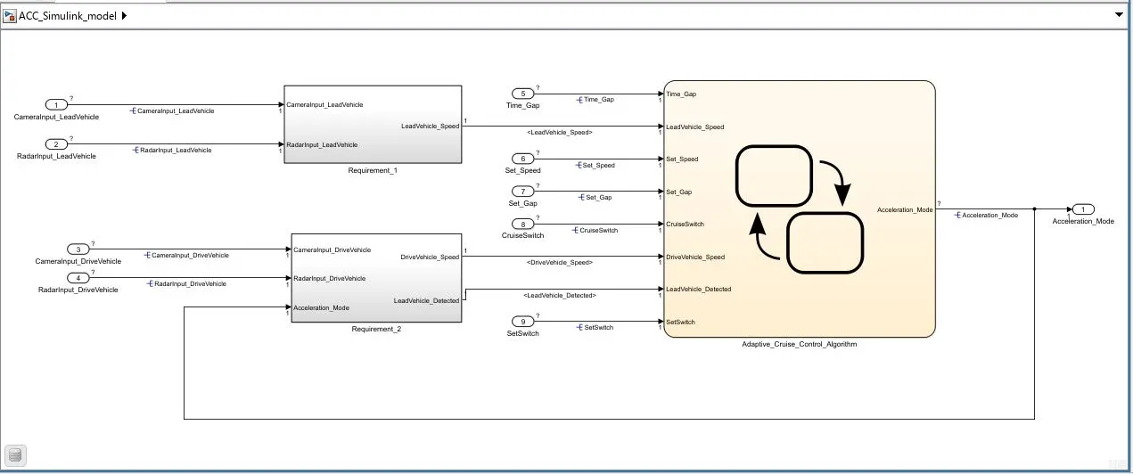
As per the given question i have build a simulink model for Adaptive Cruise Control. In that requirement 1 is Lead Vehicle, requirement 2 is Drive Vehicle, and requirement 3 contrians the ACC alogorithm.
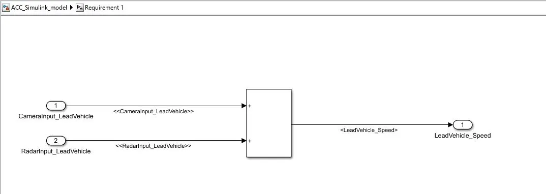
The abouve fig shows the requirement 1 subsystem. it takes camera and radar input and give output as a vehicle speed. to avoid confusion we just sum up both the inputs and get the output.
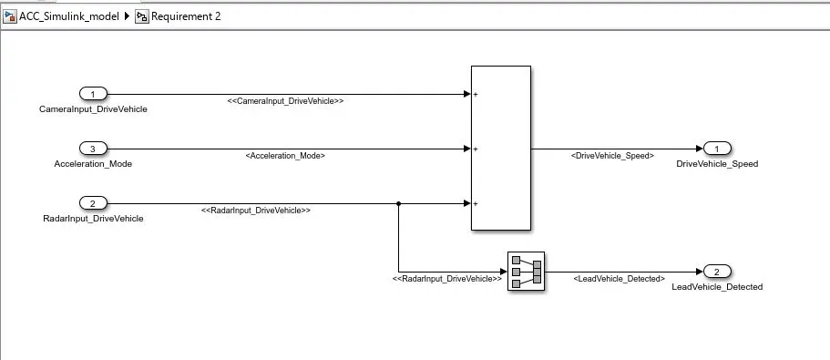
The above fig shows the subsystem of requirement 2, It takes camera , radar input and acceleration mode and give output as vehicle speed, and we can get vehicle detection output from the radar input by the use of signal conversion block. for compleaxity resons, here also we avoid algorithm insted we use sum block to get output.
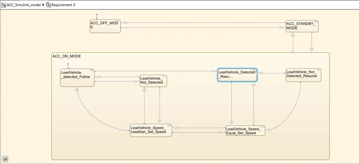

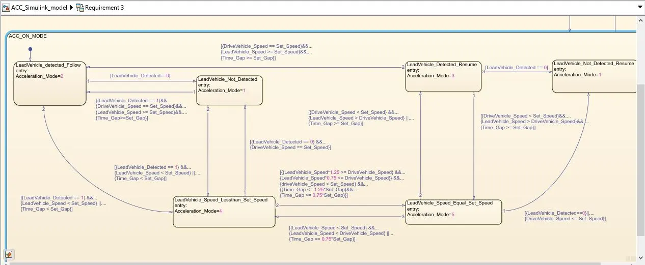
the above fig shows the algorithm of ACC.
It has three operating modes :
1. ACC OFF Mode.
2. ACC StandBy Mode.
3. ACC ON Mode.
ACC OFF Mode:
ACC of mode is the default state. the output Acceleration _mode is at '0' in this state. This state will activated by Cruise Switch, if Cruise Switch ==0, OFF mode will get activated and if Cruise Switch == 1 StandBy mode will get activated.
ACC StandBy Mode:
This is second activated state in ACC, the output Acceleration_mode is at value '1'. This state will get activated by both cruise switch and set switch.
if the cruise switch == 1 ACC StandBy mode will get activated, and if the setswitch == 0, ACC StandBy mode will get activated.
ACC ON Mode:
This mode will get activated if the set switch == 1, this state contains 6 substrates, they are:
1. LeadVehicle_detecyed_Follow (default)
2.LeadVehicle_Not_Detected.
3.LeadVehicle_Detected_Resume.
4.LeadVehicle_Not_Detected__Resume.
5.LeadVehicle_Speed_Lessthan_set_Speed
6.LeadVehicle_Speed_Equal_Set_Speed.
these substrates have different different logics and output acceleration mode is at different values. also there are transitions from one substrate to another which is shown in fig.
Requirement 3c (i) – LeadVehicle_Detected_Follow (ACC ON MODE):
- This is the default sub state inside ACC ON MODE state. Output signal Acceleration_Mode is equal to 2.
- Condition to transit from LeadVehicle_Detected_Follow to LeadVehicle_Not_Detected; Input signal condition LeadVehicle_Detected == 0.
- Condition to transit from LeadVehicle_Detected_Follow to LeadVehicle_Speed_lessthan_Set_Speed; Input Signals condition (LeadVehicle_Detected == 1) && (LeadVehicle_Speed < Set_Speed) || (Time_Gap < Set_Gap).
Requirement 3c (ii) – LeadVehicle_Not_Detected (ACC ON MODE):
- Output signal Acceleration_Mode is equal to 1.
- Condition to transit from LeadVehicle_Not_Detected to LeadVehicle_Detected_Follow; Input signals condition [(LeadVehicle_Detected==1) && (DriveVehicle_Speed == Set_Speed) && (LeadVehicle_Speed >= Set_Speed) && (Time_Gap >= Set_Gap)]
- Condition to transit from LeadVehicle_Not_Detected to LeadVehicle_Speed_lessthan_Set_Speed; Input signals condition [(LeadVehicle_Detected == 1) && (LeadVehicle_Speed < Set_Speed) || (Time_Gap < Set_Gap)]
Requirement 3c (iii) – LeadVehicle_Detected_Resume (ACC ON MODE):
- Output signal Acceleration_Mode is equal to 3.
- Condition to transit from LeadVehicle_Detected_Resume to LeadVehicle_Detected_Follow; Input signals condition [(DriveVehicle_Speed == Set_Speed) && (LeadVehicle_Speed >= Set_Speed) && (Time_Gap >= Set_Gap)]
- Condition to transit from LeadVehicle_Detected_Resume to LeadVehicle_Not_Detected_Resume; Input signal condition LeadVehicle_Detected==0.
- Condition to transit from LeadVehicle_Detected_Resume to LeadVehicle_Speed_equal_Set_Speed; Input Signal condition [(DriveVehicle_Speed < Set_Speed) && (LeadVehicle_Speed > DriveVehicle_Speed) && (Time_Gap >= Set_Gap)]
Requirement 3c (iv) - LeadVehicle_Not_Detected_Resume (ACC ON MODE):
- Output signal Acceleration_Mode is equal to 1.
Requirement 3c (v) - LeadVehicle_Speed_lessthan_Set_Speed (ACC ON MODE):
- Output signal Acceleration_Mode is equal to 4.
- Condition to transit from LeadVehicle_Speed_lessthan_Set_Speed to LeadVehicle_Not_Detected; Input signal condition [(LeadVehicle_Detected == 0) && (DriveVehicle_Speed == Set_Speed)]
- Condition to transit from LeadVehicle_Speed_lessthan_Set_Speed to LeadVehicle_Speed_equal_Set_Speed; Input signals condition [((LeadVehicle_Speed*1.25>=DriveVehicle_Speed) && (LeadVehicle_Speed * 0.75<=DriveVehicle_Speed)) && (DriveVehicle_Speed < Set_Speed) && ((Time_Gap<=1.25*Set_Gap) && (Time_Gap >=0.75*Set_Gap))]
Requirement 3c (vi) - LeadVehicle_Speed_equal_Set_Speed (ACC ON MODE):
- Output signal Acceleration_Mode is equal to 5.
- Condition to transit from LeadVehicle_Speed_equal_Set_Speed to LeadVehicle_Not_Detected_Resume; Input signal conditions is [(LeadVehicle_Detected == 0) || (DriveVehicle_Speed <= Set_Speed)]
- Condition to transit from LeadVehicle_Speed_equal_Set_Speed to LeadVehicle_Detected_Resume; Input signal conditions [(DriveVehicle_Speed < Set_Speed) && (LeadVehicle_Speed > DriveVehicle_Speed) || (Time_Gap >= Set_Gap)]
- Condition to transit from LeadVehicle_Speed_equal_Set_Speed to LeadVehicle_Speed_lessthan_Set_Speed; Input signals conditions [(LeadVehicle_Speed < Set_Speed) && (LeadVehicle_Speed < DriveVehicle_Speed)|| (Time_Gap == 0.75*Set_Gap)].
Now the Simulink Model Creation is Over.
Now we need to create DataDictionary, for that we need to go to Modelling--- link to DataDictionary---- it will ask for new or browse for old, we create new one and then create.
now model explorer with new data dictionary is opened. in that we need create data for following signals:
- CameraInput_LeadVehicle
-RadaInput_LeadVehicle
-CameraInput_DriveVehicle
-RadarInput_DriveVehicle
-Time_Gap
-Set_Speed
-Set_Gap
-CruiseSwitch
-SetSwitch
-Acceleration_Mode
-LeadVehicle_Speed
-DriveVehicle_Speed
-LeadVehicle_Detected
After creation it will look like the following:
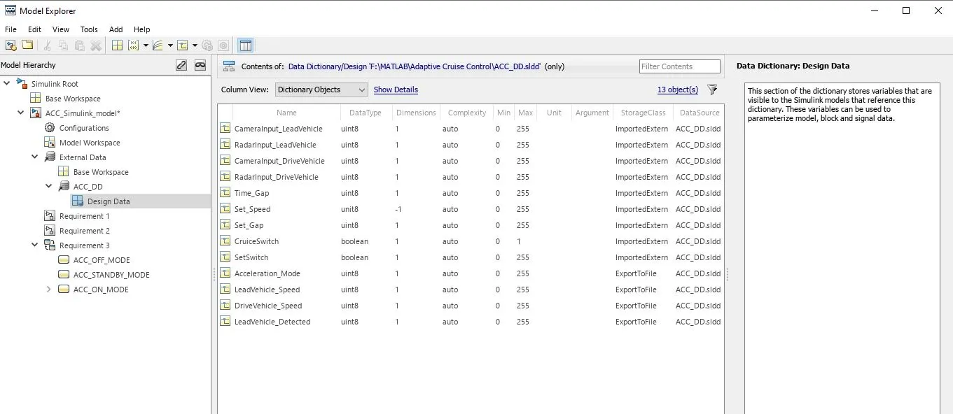
after creating signals we need to give names to the signals, and then we need to propagate them from the source points.
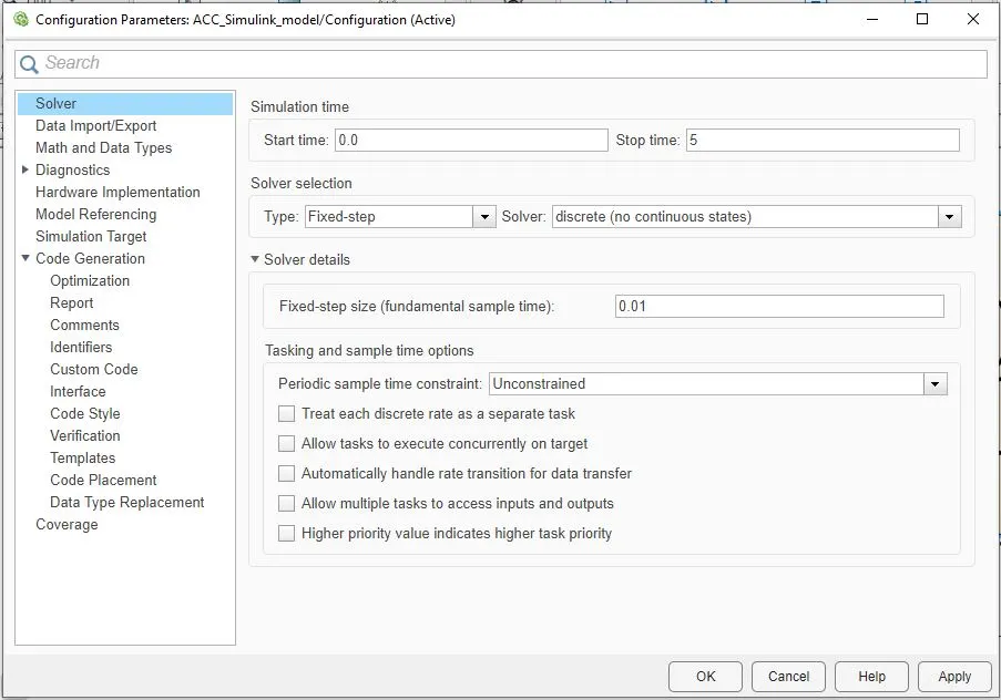
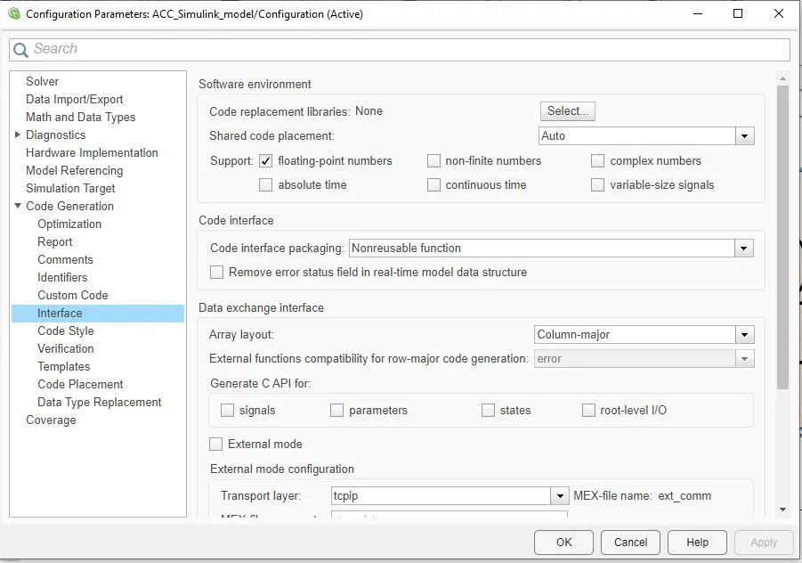
Then we need to configure parameters in the configuration parameters window...
-for Solver, we need to use fixed-step type and discrete solver with step-size of 0.01.
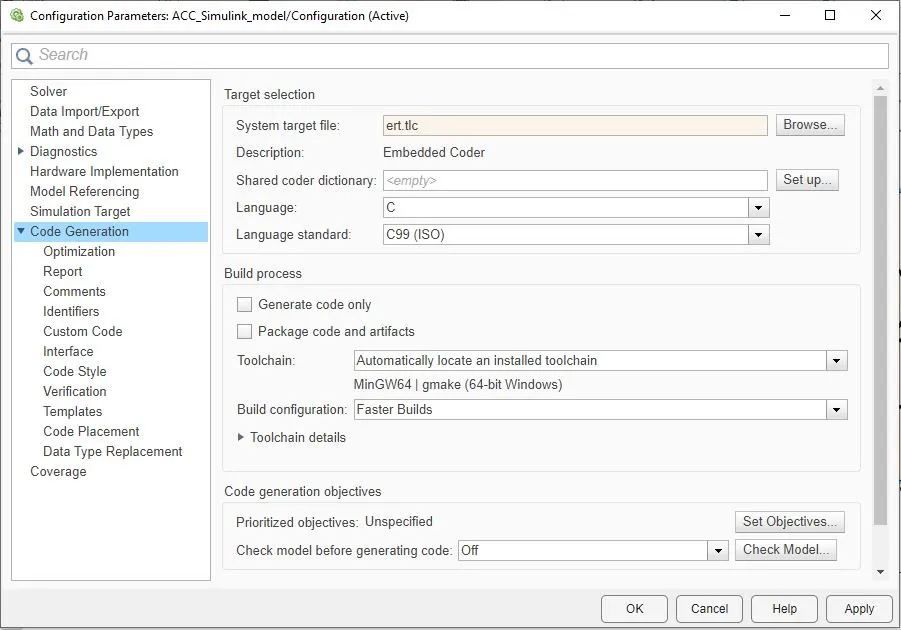
in the code generation , we need to use embedded coder and we need to tick on support floating numbers.
Then Model Advisor, for that we need to go to modelling---model advisor---- we need to select for which we need model advisor report, here i choose whole model for report.
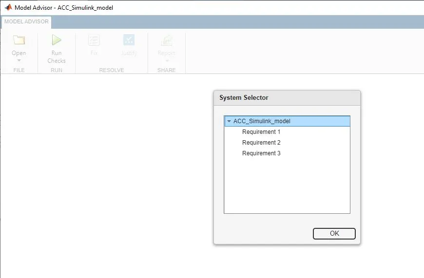
then model advisor window will open, in that we need to run test for "Modelling standards for MAB".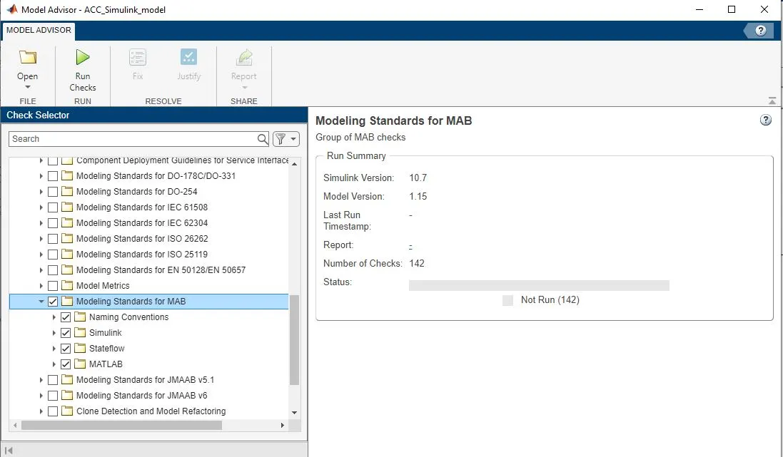
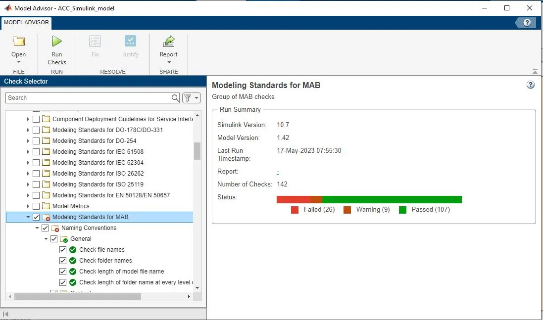
.Here we are checking whether our model acceptable according to MAB guidelines. Then a repor will appear with how many are failed, how many passed and how many warnings we have. after getting the report we need reduce as many warnings as we can.
The final report i got was
now, requirement tagging, for requirement tagging first we need to select text in word document, then go to requirement 1 in the model---right click---reequirements----link to selection in word. similarly, for requirement 2 and 3.
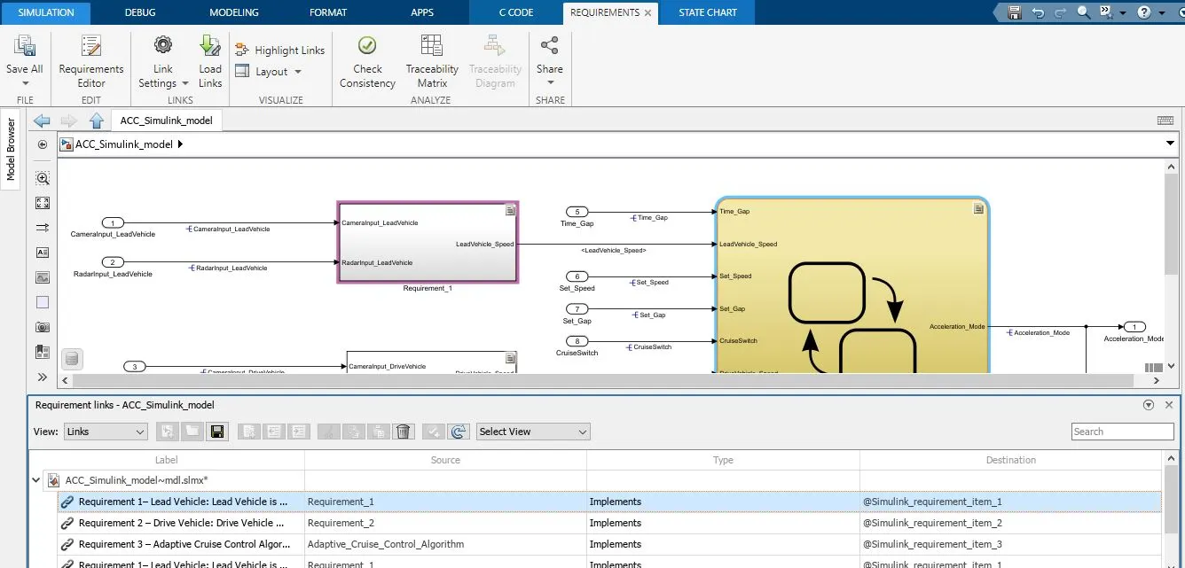
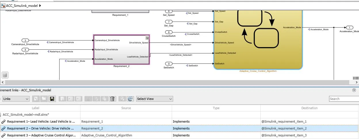
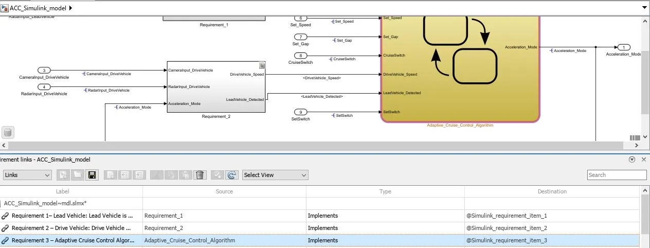
after requirement tagging final one is code geneartion, for the code generation first we need o build this model and then code generation. for that go to Apps-embedded coder, then go to build. then it will build the code and generate code generation report.
for me i have got some error and because of that I'm unable to generate code.

Result:
Successfully created Simulink model for Adaptive Cruise Control, simulink Data Dictionary, able to add requirement tagging and able to generate model Advisory report.