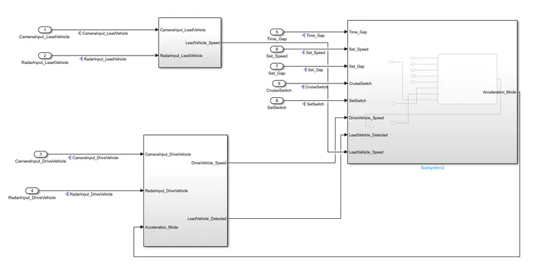
Project 2 Adaptive Cruise Control
// Mahanmadijaj Shekh
Main Project Adaptive Cruise Control (ACC)
Objective of Main Project:
- Developing Adaptive Cruise Control feature as per the Requirement Document using MATLAB Simulink.
- Follow all the MBD related processes: Requirement Tagging & Traceability, SLDD creation, Configuration Parameter changes, Model Advisor check & Code Generation.
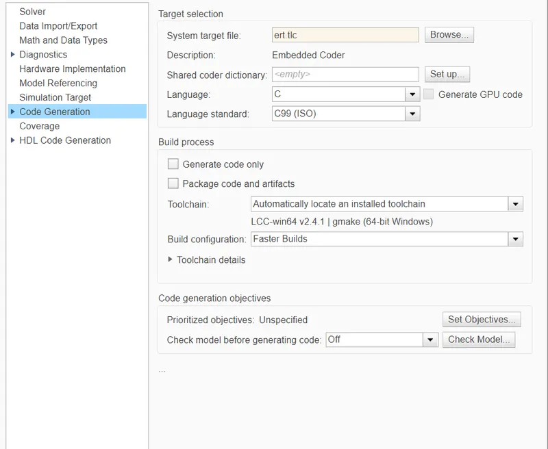
- In Configuration Parameters: enable “Support Floating Numbers” under Code Generation settings.
- Use Embedded Coder to generate the code.
- If choosing code generation, Storage class for Input signals: ImportedExtern; Storage class for Output signal: Export to File; Storage class for local signals: localizable; Storage class for calibration signals: Const.
- Choose sample time for all signals as 0.01s
Requirement 1– Lead Vehicle:
- Lead Vehicle is a vehicle which is driving in the road ahead of our drive vehicle. Two input signals (Signal Name: CameraInput_LeadVehicle & RadarInput_LeadVehicle).
- Ideally sensor fusion techniques will be deployed to process & analyze data from camera & radar. For complexity reasons, let’s not adapt to any such algorithms.
- We can simply add both the radar & camera inputs & the corresponding output is read as Speed profile output (Signal Name: LeadVehicle_Speed).
- Speed data of the lead vehicle is critical in implementing the Adaptive Cruise Control algorithm.
Requirement 2 – Drive Vehicle:
- Drive Vehicle is the vehicle driven by the user & this is the vehicle which has ACC algorithm in it.
- Like the Lead Vehicle, Drive Vehicle algorithm also has 2 input signals (Signal Name: CameraInput_DriveVehicle, RadarInput_DriveVehicle) & one signal coming as an Input to this subsystem (Signal Name: Acceleration_Mode) – three inputs into this requirement in total.
- Like the above requirement, sensor fusion techniques will also be deployed here, for complexity reasons we are ignoring them.
- Two output signals come from this subsystem (Signal Name: DriveVehicle_Speed & LeadVehicle_Detected).
- Signal DriveVehicle_Speed is summation of three input signals mentioned above & LeadVehicle_Detected is renamed from Input Signal RadarInput_DriveVehicle by mere use of Signal Conversion block.
Requirement 3 – Adaptive Cruise Control Algorithm:
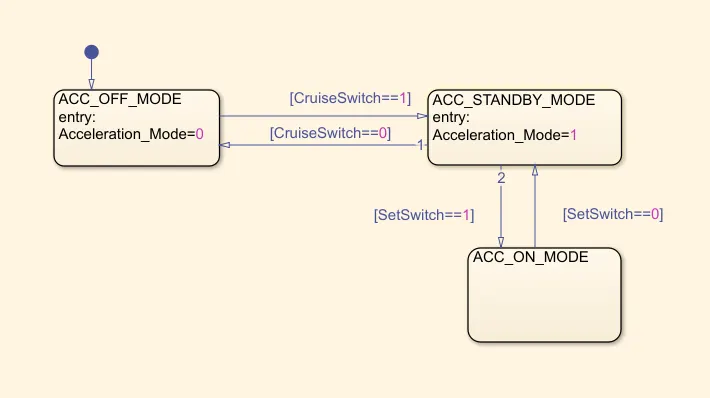
- Adaptive Cruise Control feature has 3 major modes of operation: OFF Mode, STANDBY Mode & ON Mode. This particular requirement has to be implemented as state machine logic in Simulink.
- The input signals to this state machine system are (Signal Name: Time_Gap, Set_Speed, Set_Gap, CruiseSwitch, SetSwitch).
- Also, the output signals (Signal Name: DriveVehicle_Speed & LeadVehicle_Detected) from requirement-2 is fed back as an input signal into this state machine block.
- Additionally, output signal (Signal Name: LeadVehicle_Speed) from requirement-1 is given as an input signal to this state machine block as well.
- Output from this subsystem is a signal (Signal Name: Acceleration_Mode) which governs the vehicular speed of the drive vehicle which automatically adjusts its speed & velocity to match the lead vehicle.
Requirement 3a – ACC OFF MODE state logic:
- This is the default state inside state machine logic. Output signal Acceleration_Mode is at value 0 in this state.
- This state is governed by input signal CruiseSwitch.
- If CruiseSwitch is equal to 1, state ACC STANDBY mode will get activated. If CruiseSwitch is equal to 0, state ACC OFF mode will get activated, from either ACC ON mode or ACC STANDBY mode
Requirement 3b – ACC STANDBY MODE state logic:
- This is the second activated state inside state machine logic. Output signal Acceleration_Mode is at value 1 in this state.
- This state is governed by both input signals CruiseSwitch & SetSwitch.
- If CruiseSwitch is equal to 1, state ACC STANDBY mode will get activated. If CruiseSwitch is equal to 0, state ACC OFF mode will get activated, from either ACC ON mode or ACC STANDBY mode
- If SetSwitch is equal to 1, state ACC ON mode will get activated. If SetSwitch is equal to 0, state ACC STANDBY mode will get activated.
Requirement 3c – ACC ON MODE state logic:
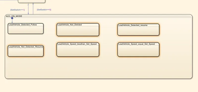
This state will be activated when input signal SetSwitch is equal to 1. There are 6 sub states to this state logic: They are:
- LeadVehicle_Detected_Follow (Default)
- LeadVehicle_Not_Detected
- LeadVehicle_Detected_Resume
- LeadVehicle_Not_Detected_Resume
- LeadVehicle_Speed_lessthan_Set_Speed
- LeadVehicle_Speed_equal_Set_Speed
Requirement 3c (i) – LeadVehicle_Detected_Follow (ACC ON MODE):
- This is the default sub state inside ACC ON MODE state. Output signal Acceleration_Mode is equal to 2.
- Condition to transit from LeadVehicle_Detected_Follow to LeadVehicle_Not_Detected; Input signal condition LeadVehicle_Detected == 0.
- Condition to transit from LeadVehicle_Detected_Follow to LeadVehicle_Speed_lessthan_Set_Speed; Input Signals condition (LeadVehicle_Detected == 1) && (LeadVehicle_Speed < Set_Speed) || (Time_Gap < Set_Gap).
Requirement 3c (ii) – LeadVehicle_Not_Detected (ACC ON MODE):
- Output signal Acceleration_Mode is equal to 1.
- Condition to transit from LeadVehicle_Not_Detected to LeadVehicle_Detected_Follow; Input signals condition [(LeadVehicle_Detected==1) && (DriveVehicle_Speed == Set_Speed) && (LeadVehicle_Speed >= Set_Speed) && (Time_Gap >= Set_Gap)]
- Condition to transit from LeadVehicle_Not_Detected to LeadVehicle_Speed_lessthan_Set_Speed; Input signals condition [(LeadVehicle_Detected == 1) && (LeadVehicle_Speed < Set_Speed) || (Time_Gap < Set_Gap)]
Requirement 3c (iii) – LeadVehicle_Detected_Resume (ACC ON MODE):
- Output signal Acceleration_Mode is equal to 3.
- Condition to transit from LeadVehicle_Detected_Resume to LeadVehicle_Detected_Follow; Input signals condition [(DriveVehicle_Speed == Set_Speed) && (LeadVehicle_Speed >= Set_Speed) && (Time_Gap >= Set_Gap)]
- Condition to transit from LeadVehicle_Detected_Resume to LeadVehicle_Not_Detected_Resume; Input signal condition LeadVehicle_Detected==0.
- Condition to transit from LeadVehicle_Detected_Resume to LeadVehicle_Speed_equal_Set_Speed; Input Signal condition [(DriveVehicle_Speed < Set_Speed) && (LeadVehicle_Speed > DriveVehicle_Speed) && (Time_Gap >= Set_Gap)]
Requirement 3c (iv) - LeadVehicle_Not_Detected_Resume (ACC ON MODE):
- Output signal Acceleration_Mode is equal to 1.
Requirement 3c (v) - LeadVehicle_Speed_lessthan_Set_Speed (ACC ON MODE):
- Output signal Acceleration_Mode is equal to 4.
- Condition to transit from LeadVehicle_Speed_lessthan_Set_Speed to LeadVehicle_Not_Detected; Input signal condition [(LeadVehicle_Detected == 0) && (DriveVehicle_Speed == Set_Speed)]
- Condition to transit from LeadVehicle_Speed_lessthan_Set_Speed to LeadVehicle_Speed_equal_Set_Speed; Input signals condition [((LeadVehicle_Speed*1.25>=DriveVehicle_Speed) && (LeadVehicle_Speed * 0.75<=DriveVehicle_Speed)) && (DriveVehicle_Speed < Set_Speed) && ((Time_Gap<=1.25*Set_Gap) && (Time_Gap >=0.75*Set_Gap))]
Requirement 3c (vi) - LeadVehicle_Speed_equal_Set_Speed (ACC ON MODE):
- Output signal Acceleration_Mode is equal to 5.
- Condition to transit from LeadVehicle_Speed_equal_Set_Speed to LeadVehicle_Not_Detected_Resume; Input signal conditions is [(LeadVehicle_Detected == 0) || (DriveVehicle_Speed <= Set_Speed)]
- Condition to transit from LeadVehicle_Speed_equal_Set_Speed to LeadVehicle_Detected_Resume; Input signal conditions [(DriveVehicle_Speed < Set_Speed) && (LeadVehicle_Speed > DriveVehicle_Speed) || (Time_Gap >= Set_Gap)]
- Condition to transit from LeadVehicle_Speed_equal_Set_Speed to LeadVehicle_Speed_lessthan_Set_Speed; Input signals conditions [(LeadVehicle_Speed<Set_Speed) && (LeadVehicle_Speed<DriveVehicle_Speed) || (Time_Gap == 0.75*Set_Gap)]
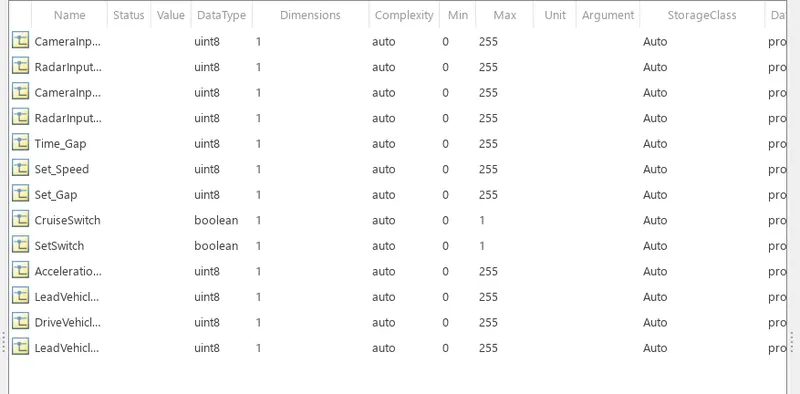
Creation of Simulink Data Dictionary file (SLDD):
A Simulink Data Dictionary (SLDD) file is created that contains input, output signals and calibration parameters used in the model. SLDD file is created by clicking on Modeling, then ‘Model Properties’, then ‘External Data’ and specifying a file name for the Data Dictionary
Requirement 1– Lead Vehicle:
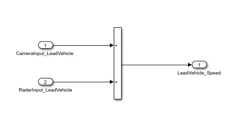
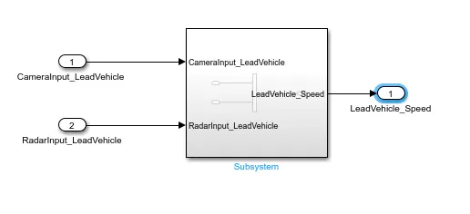
- A lead vehicle is a vehicle that is driving in the road ahead of our drive vehicle. Two input signals (Signal Name: CameraInput_LeadVehicle & RadarInput_LeadVehicle).
- Ideally, sensor fusion techniques will be deployed to process & analyze data from cameras & radar. For complexity reasons, let’s not adapt to any such algorithms.
- We can simply add both the radar & camera inputs & the corresponding output is read as Speed profile output (Signal Name: LeadVehicle_Speed).
- Speed data of the lead vehicle is critical in implementing the Adaptive Cruise Control algorithm.
Lead Vehicle
Requirement 2 – Drive Vehicle:
- Drive Vehicle is the vehicle driven by the user & this is the vehicle that has ACC algorithm in it.
- Like the Lead Vehicle, the Driver Vehicle algorithm also has 2 input signals (Signal Name: CameraInput_DriveVehicle, RadarInput_DriveVehicle) & one signal coming as an Input to this subsystem (Signal Name: Acceleration_Mode) – three inputs into this requirement in total.
- Like the above requirement, sensor fusion techniques will also be deployed here, for complexity reasons we are ignoring them.
- Two output signals come from this subsystem (Signal Name: DriveVehicle_Speed & LeadVehicle_Detected).
- Signal DriveVehicle_Speed is the summation of three input signals mentioned above & LeadVehicle_Detected is renamed from Input Signal RadarInput_DriveVehicle by mere use of Signal Conversion block.
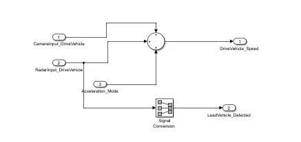
DRIVE VEHICLE -
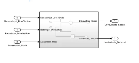
Before proceeding to Requirement 3, we have to turn off the content preview of the subsystems
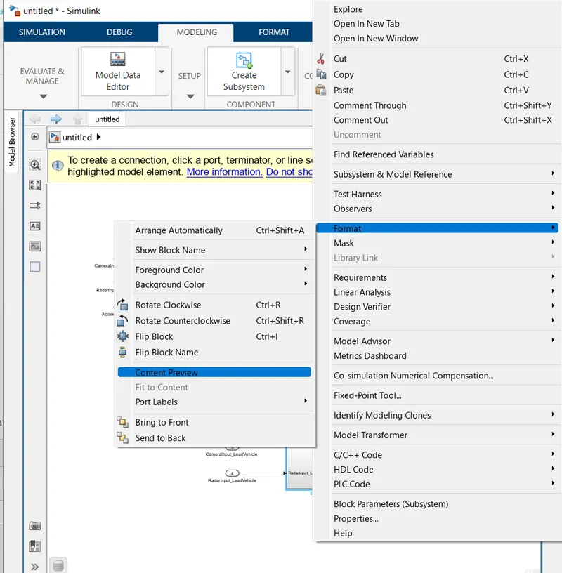
Requirement 3 – Adaptive Cruise Control Algorithm:
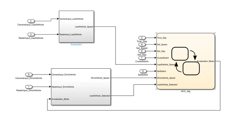
- Adaptive Cruise Control feature has 3 major modes of operation: OFF Mode, STANDBY Mode & ON Mode. This particular requirement has to be implemented as state machine logic in Simulink.
- The input signals to this state machine system are (Signal Name: Time_Gap, Set_Speed, Set_Gap, CruiseSwitch, SetSwitch).
- Also, the output signals (Signal Name: DriveVehicle_Speed & LeadVehicle_Detected) from requirement-2 are fed back as an input signal into this state machine block.
- Additionally, the output signal (Signal Name: LeadVehicle_Speed) from requirement-1 is given as an input signal to this state machine block as well.
- Output from this subsystem is a signal (Signal Name: Acceleration_Mode) that governs the vehicular speed of the drive vehicle which automatically adjusts its speed & velocity to match the lead vehicle.
For Requirement 3, select a Chart Block name it " ACC_Alg"
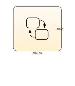 Then click on the Chart Block and it gets selected then go to Model Explorer.
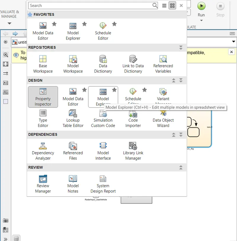
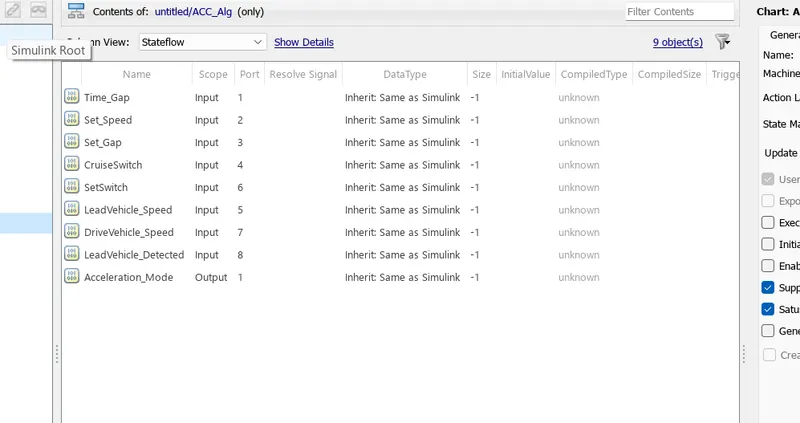
Add all the Input and output signals as shown below.
After adding all the signals in the Model explorer close the window.
Connect all the input and out according to the name mentioned in the block.
ADAPTIVE CRUISE CONTROL -
Requirement 3a – ACC OFF MODE state logic:
- This is the default state inside state machine logic. Output signal Acceleration_Mode is at value 0 in this state.
- This state is governed by the input signal CruiseSwitch.
- If CruiseSwitch is equal to 1, state ACC STANDBY mode will get activated. If CruiseSwitch is equal to 0, state ACC OFF mode will get activated, from either ACC ON mode or ACC STANDBY mode
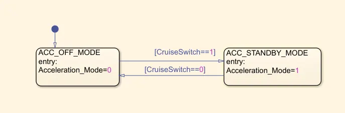
Requirement 3b – ACC STANDBY MODE state logic:
- This is the second activated state inside state machine logic. Output signal Acceleration_Mode is at value 1 in this state.
- This state is governed by both input signals CruiseSwitch & SetSwitch.
- If CruiseSwitch is equal to 1, state ACC STANDBY mode will get activated. If CruiseSwitch is equal to 0, state ACC OFF mode will get activated, from either ACC ON mode or ACC STANDBY mode
- If SetSwitch is equal to 1, state ACC ON mode will get activated. If SetSwitch is equal to 0, state ACC STANDBY mode will get activated.
Requirement 3c – ACC ON MODE state logic:
This state will be activated when the input signal SetSwitch is equal to 1. There are 6 sub-states to this state logic: They are:
- LeadVehicle_Detected_Follow (Default)
- LeadVehicle_Not_Detected
- LeadVehicle_Detected_Resume
- LeadVehicle_Not_Detected_Resume
- LeadVehicle_Speed_lessthan_Set_Speed
- LeadVehicle_Speed_equal_Set_Speed
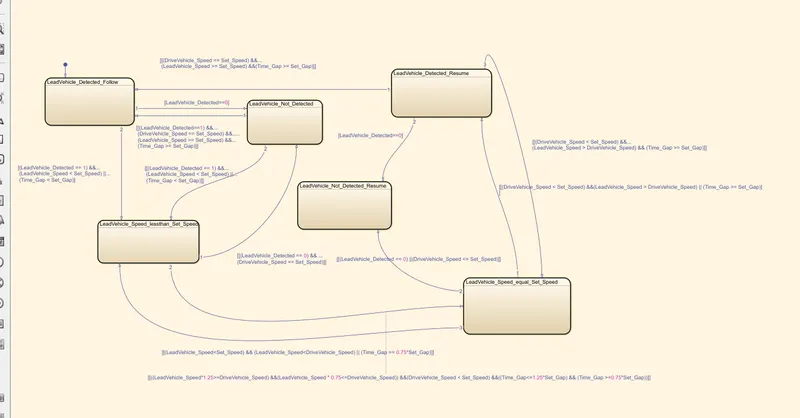
Requirement 3c (i) – LeadVehicle_Detected_Follow (ACC ON MODE):
- This is the default sub-state inside the ACC ON MODE state. Output signal Acceleration_Mode is equal to 2.
- Condition to transit from LeadVehicle_Detected_Follow to LeadVehicle_Not_Detected; Input signal condition LeadVehicle_Detected == 0.
- Condition to transit from LeadVehicle_Detected_Follow to LeadVehicle_Speed_lessthan_Set_Speed; Input Signals condition (LeadVehicle_Detected == 1) && (LeadVehicle_Speed < Set_Speed) || (Time_Gap < Set_Gap).
Requirement 3c (ii) – LeadVehicle_Not_Detected (ACC ON MODE):
- Output signal Acceleration_Mode is equal to 1.
- Condition to transit from LeadVehicle_Not_Detected to LeadVehicle_Detected_Follow; Input signals condition [(LeadVehicle_Detected==1) && (DriveVehicle_Speed == Set_Speed) && (LeadVehicle_Speed >= Set_Speed) && (Time_Gap >= Set_Gap)]
- Condition to transit from LeadVehicle_Not_Detected to LeadVehicle_Speed_lessthan_Set_Speed; Input signals condition [(LeadVehicle_Detected == 1) && (LeadVehicle_Speed < Set_Speed) || (Time_Gap < Set_Gap)]
Requirement 3c (iii) – LeadVehicle_Detected_Resume (ACC ON MODE):
- Output signal Acceleration_Mode is equal to 3.
- Condition to transit from LeadVehicle_Detected_Resume to LeadVehicle_Detected_Follow; Input signals condition [(DriveVehicle_Speed == Set_Speed) && (LeadVehicle_Speed >= Set_Speed) && (Time_Gap >= Set_Gap)]
- Condition to transit from LeadVehicle_Detected_Resume to LeadVehicle_Not_Detected_Resume; Input signal condition LeadVehicle_Detected==0.
- Condition to transit from LeadVehicle_Detected_Resume to LeadVehicle_Speed_equal_Set_Speed; Input Signal condition [(DriveVehicle_Speed < Set_Speed) && (LeadVehicle_Speed > DriveVehicle_Speed) && (Time_Gap >= Set_Gap)]
Requirement 3c (iv) - LeadVehicle_Not_Detected_Resume (ACC ON MODE):
- Output signal Acceleration_Mode is equal to 1.
Requirement 3c (v) - LeadVehicle_Speed_lessthan_Set_Speed (ACC ON MODE):
- Output signal Acceleration_Mode is equal to 4.
- Condition to transit from LeadVehicle_Speed_lessthan_Set_Speed to LeadVehicle_Not_Detected; Input signal condition [(LeadVehicle_Detected == 0) && (DriveVehicle_Speed == Set_Speed)]
- Condition to transit from LeadVehicle_Speed_lessthan_Set_Speed to LeadVehicle_Speed_equal_Set_Speed; Input signals condition [((LeadVehicle_Speed*1.25>=DriveVehicle_Speed) && (LeadVehicle_Speed * 0.75<=DriveVehicle_Speed)) && (DriveVehicle_Speed < Set_Speed) && ((Time_Gap<=1.25*Set_Gap) && (Time_Gap >=0.75*Set_Gap))]
Requirement 3c (vi) - LeadVehicle_Speed_equal_Set_Speed (ACC ON MODE):
- Output signal Acceleration_Mode is equal to 5.
- Condition to transit from LeadVehicle_Speed_equal_Set_Speed to LeadVehicle_Not_Detected_Resume; Input signal conditions is [(LeadVehicle_Detected == 0) || (DriveVehicle_Speed <= Set_Speed)]
- Condition to transit from LeadVehicle_Speed_equal_Set_Speed to LeadVehicle_Detected_Resume; Input signal conditions [(DriveVehicle_Speed < Set_Speed) && (LeadVehicle_Speed > DriveVehicle_Speed) || (Time_Gap >= Set_Gap)]
- Condition to transit from LeadVehicle_Speed_equal_Set_Speed to LeadVehicle_Speed_lessthan_Set_Speed; Input signals conditions [(LeadVehicle_Speed
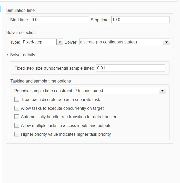
change the Following setting-
solver type: Fixed-step
Fixed-step size: 0.01
So, the Following Screenshot is the final Model as Required, now we have to generate the Advisor Report.