Project 2 Adaptive Cruise Control
Main Project – Objectives.
Here we discussed on these topics
- To Developing Adaptive Cruise Control feature as per the Requirement Document using MATLAB Simulink.
- To Follow all the MBD related processes: Requirement Tagging & Traceability, SLDD creation, Configuration Parameter changes, Model Advisor check & Code Generation.
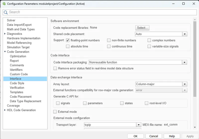
- In Configuration Parameters: enable “Support Floating Numbers” under Code Generation settings.
- Use Embedded Coder to generate the code.
- If choosing code generation, Storage class for Input signals: ImportedExtern; Storage class for Output signal: Export to File; Storage class for local signals: localizable; Storage class for calibration signals: Const.
- Choose the sample time for all signals as 0.01s.
Adaptive Cruise Control (ACC) :
Adaptive cruise control (ACC) is an available cruise control advanced driver assistant system for road vehicles that automatically adjusts the vehicle speed to maintain a safe distance from vehicles ahead. As of 2019, it is also called by 20 unique names that describe that basic functionality. This is also known as Dynamic cruise control.
Control is based on sensor information from on-board sensors. Such systems may use a radar or laser sensor or a camera setup allowing the vehicle to brake when it detects the car is approaching another vehicle ahead, then accelerate when traffic allows it to.
ACC technology is regarded as a key component of future generations of intelligent cars. The technology enhances passenger safety and convenience as well as increasing road capacity by maintaining optimal separation between vehicles and reducing driver errors. Vehicles with autonomous cruise control are considered a Level 1autonomous car, as defined by SAE international. When combined with another driver assist feature such as Lane centering, the vehicle is considered a Level 2 autonomous car.
Adaptive cruise control does not provide full autonomy: the system only provides some help to the driver, but does not drive the car by itself.
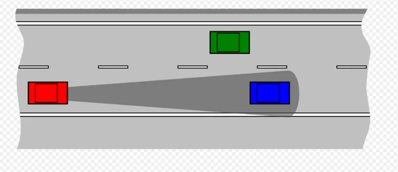
Schematic of Intelligent Cruise Control. The red car automatically maintains a safe distance from the blue car.
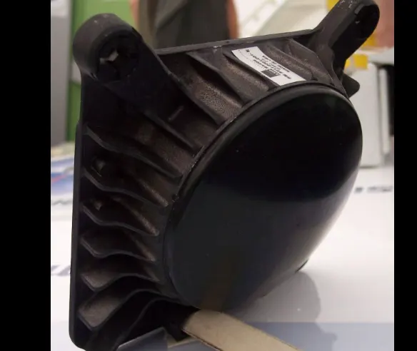
 ACC radar antenna is showing in below diagram...
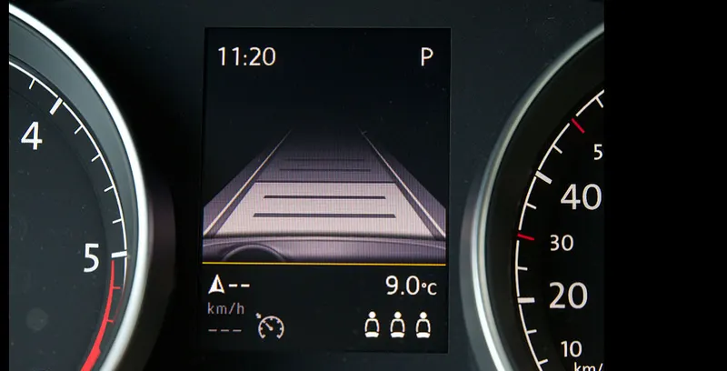
Autonomous cruise control on VW Golf
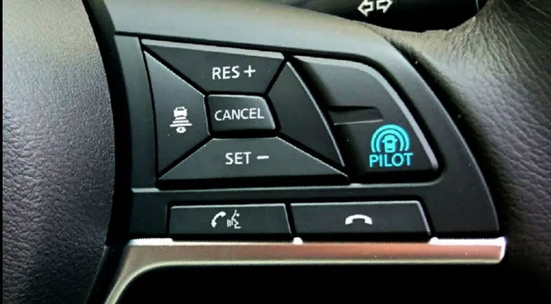
Intelligent Cruise Control (ICC) SteeringSwitch (ProPilot) Nissan Serena
Mercedes-Benz S 450 4MATIC Coupe. The forward-facing Distronic sensors are usually placed behind the Mercedes-Benz logo and front grille.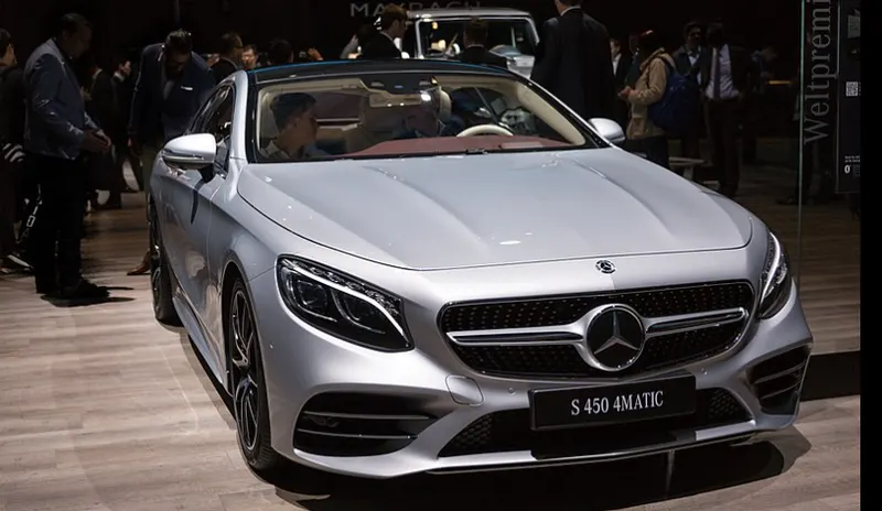
What is the difference between normal cruise control and adaptive cruise control?
The origins of normal cruise control go back to 1948, when Ralph Teetor invented the speedostat. Having greatly improved since, its focus on throttle control is still central to automation today. One example is automatically pressing the acceleration pedal, which enables drivers to take their foot off the pedal for a few moments when they are on a motorway with low traffic.
In the late 1990s, several carmakers started introducing a new generation of cruise control: adaptive cruise control. This technology relies on front radar to address the biggest limitation traditional cruise control had: the ability to correctly appreciate the speed of the vehicle in front.
This improvement significantly expanded the continuous operation time of the cruise control function, as automation allowed to control both the acceleration and braking of a vehicle. This allowed the driver to travel for longer distances with their feet off the pedal, even in moderate traffic situations on the motorway. Of course, the need for them to pay attention to the road ahead remained, as cars in front could still brake or suddenly cut in.
As drivers are getting more and more comfortable with using ACC while driving, the expectation for an even longer duration of continuous operation time for the system is rising. In turn, this puts pressure for it to be further improved. As new enhancements are made, the market is shifting to a new standard in ACC, called intelligent cruise control.
What use cases are supported by modern adaptive cruise control?
The latest intelligent cruise control systems aim to tackle the entire journey, offloading the driver’s tasks whenever possible. Here are some of the most interesting use cases:
Stop & Go cruise control
This is where Stop & Go cruise control can play a role. Operating similarly to adaptive cruise control on motorways, the difference is in slow-moving traffic, when it automatically stops or starts vehicle movement under driver supervision. The car will brake and accelerate on its own, while maintaining a safe distance from the vehicle in front.
Speed limit-aware cruise control
one of the situations requiring ACC adjustment by the driver is when passing a speed limit sign. However, intelligent cruise control can automatically adjust the set speed to the newly detected speed limit, thanks to input from the traffic sign recognition system. This is done by fusing camera observation and map data to provide reliable speed restriction information
Eco cruise control for fuel and EV capacity savings
When in eco mode, cruise control adjusts the set speed so that the minimum amount of energy – whether electricity or fuel – is consumed during the journey. In a situation where a vehicle would go uphill, the system could drop the speed of the vehicle with 15-20%, in appreciation of the expected downhill speed gain shortly after.
Cruise control in curves
Especially on country roads and junctions, but also on motorways, the driver usually needs to correct the speed set by adaptive cruise control when facing bends and turns.
Using curvature data from the ADAS Map, intelligent cruise control can eliminate human intervention by calculating the safe and comfortable speed for a given road segment. It does so by also considering specific vehicle dynamics.
Turn-by-turn cruise control
One of the most recent advancements in intelligent cruise control technology is the capability to automate acceleration and braking at highway exits, entrances, junctions and roundabouts. Even when a driver corrects the vehicle speed by braking, as soon as the pedal is released, the system resumes its activity and sets the speed according to the upcoming road feature it detects.
Map data is critical to this operation, as the system relies on insights based on traffic signs – stop, yield, traffic lights – and curvature at junction information.
Predictive adaptive cruise control to anticipate road hazards ahead
When there is a road accident, a broken vehicle on the road or severe weather conditions such as icy roads, special caution when driving is required. Intelligent cruise control systems rely on the vehicle’s connectivity to obtain early warnings and adjust speed accordingly. The result is a safer and more comfortable journey for the driver and passengers.
Parking speed control
The first and the last stage of a car journey with adaptive cruise control is always the same: controlling the speed when maneuvering in a parking or a driveway. To assist the driver in such a scenario, it is imperative to use additional sensing and very low speed.
Currently, many ACC systems under development target not only self-parking, but also maneuvering through large parking lots.
Dynamic priority cruise control: an emerging technology
The next step for modern adaptive cruise control systems is the ability to perceive and automatically handle changing traffic lights and other vehicles at junctions. Intelligent driving strategies that support this use case include priority negotiation and sensing a rapidly changing situation with high confidence. Of course, the driver can still observe the vehicle’s choices and intervene at any given moment.
Future of adaptive cruise control
The benefits of adaptive cruise control make it a worthwhile technology to continue investing in. It provides longitudinal control of a vehicle, such as acceleration and braking. Increasingly, it can be combined with steering assist technology like lane centering for automated lane changes. The longitudinal and lateral control systems working together leads to autonomous driving, the next mobility revolution, which is expected to evolve rapidly over the next decade.
TomTom creates technologies for a moving world that supports all levels of autonomous driving. To learn more about how the ADAS Map is already powering automated vehicles on the road today, download the product sheet.
Signals and calibration data List is given by question are
Signals & Calibration Data List:
|
Signal / Calibration Name |
Signal Type |
Data Type |
Dimension |
Min |
Max |
Initial Value |
Units |
|
CameraInput_LeadVehicle |
Input |
Uint8 |
1 |
0 |
255 |
- |
- |
|
RadarInput_LeadVehicle |
Input |
Uint8 |
1 |
0 |
255 |
- |
- |
|
CameraInput_DriveVehicle |
Input |
Uint8 |
1 |
0 |
255 |
- |
- |
|
RadarInput_DriveVehicle |
Input |
Uint8 |
1 |
0 |
255 |
- |
- |
|
Time_Gap |
Input |
Uint8 |
1 |
0 |
255 |
- |
- |
|
Set_Speed |
Input |
Uint8 |
1 |
0 |
255 |
- |
- |
|
Set_Gap |
Input |
Uint8 |
1 |
0 |
255 |
- |
- |
|
CruiseSwitch |
Input |
Boolean |
1 |
0 |
1 |
- |
- |
|
SetSwitch |
Input |
Boolean |
1 |
0 |
1 |
- |
- |
|
Acceleration_Mode |
Output |
Uint8 |
1 |
0 |
255 |
- |
- |
|
LeadVehicle_Speed |
Output |
Uint8 |
1 |
0 |
255 |
- |
- |
|
DriveVehicle_Speed |
Output |
Uint8 |
1 |
0 |
255 |
- |
- |
|
LeadVehicle_Detected |
Output |
Uint8 |
1 |
0 |
255 |
- |
- |
- To Follow all the MBD related processes: Requirement Tagging & Traceability, SLDD creation, Configuration Parameter changes, Model Advisor check & Code Generation.
Here we open the matlab window check the current folder conatin the Modelbase_major project folder and open that folder . Then check correct folder path or not and then open the simulink model file and simulink script file also.
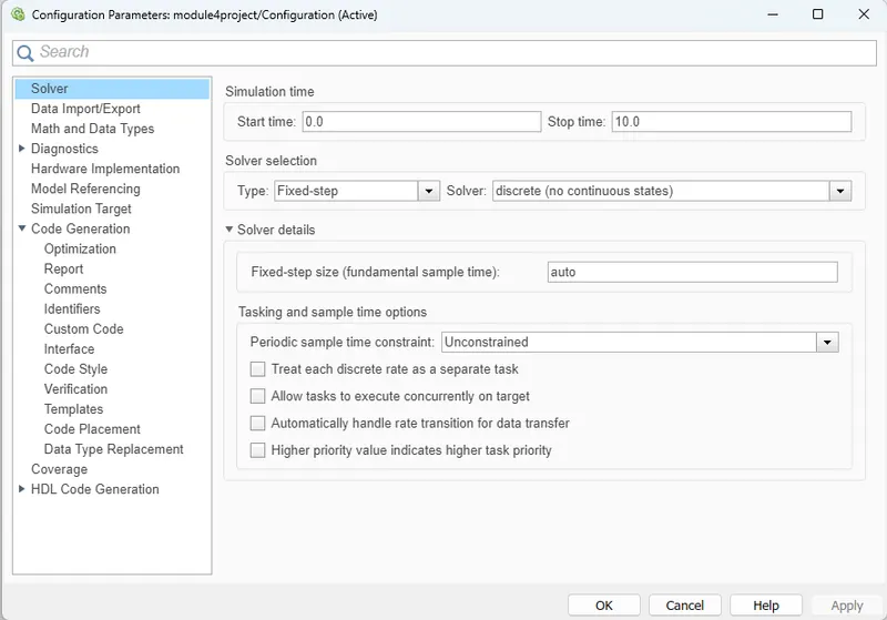
After Goto the model settings then went to solver then chanage the parameters of solver selection type and solver to fixed varible and Discrete solver and then change the Fixed step size to 0.01 click ok. Its shown in below figure.
After we change the parameters in model settingfs are shown below.
In code generation settings the file is to be converted in to the embedded coder,
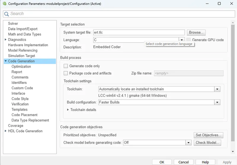
after selection the code generation and select the code generation parameter select the interface and in that select the floating points at shared code placement.
Here goto the interface block we can change the support in floating point numbers then the parameter of the interface is
After that we can create the simulink data dictionary file (SLDD) file so we can enter the signal and calibration in to the sldd file, before that we just add a path aa file sldd to save it so we can save the file
So first we goto the l link to dictionary file in modelling block,
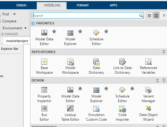
then create the sldd file as module4project.sldd and with the desired path for particular folder.
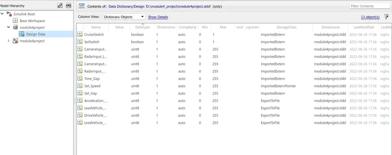
After that open the simulink model page and in that goto modelling window and in that select model explorer window enter the signals and data type , dimensions, complexitiy min and max , storage class values as shown below and save the design data sheet
We can add the signal calibration list in to the sldd dictionary afte create the file we have to save it.
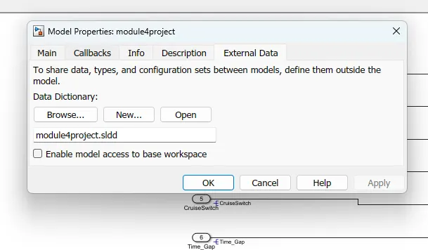
After creating the SLDD file again open the modelling in that open model explorer window and check the SLDD file is in the extrenal data
To Developing Adaptive Cruise Control feature as per the Requirement Document using MATLAB Simulink :
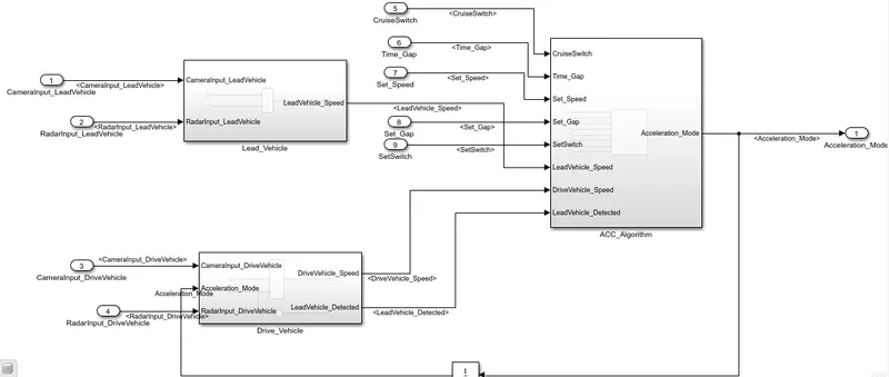
Simulation model for the Adaptive Cruise Control method and along with the subsystem with their requirements are shown below.
If we create a simulink file and Simulation model for the Adaptive Cruise Contorl method and along with the subsystem with their requirements are shown below.
This is the main block diagram of the adpative cruise control ,so we can study for every parameter in detailed,
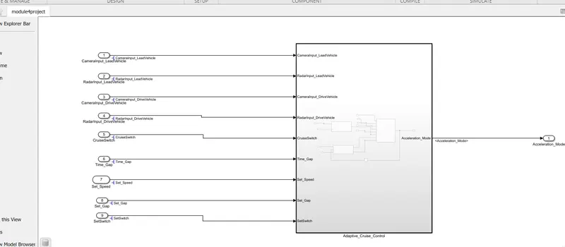
In The above model is Adaptive Cruise Control (ACC) is to be design main model. in the main model we are created 3 individaul sub systems they are
Lead_ Vehicle Subsystem
Drive_ vehicle Subsystem
ACC_ Logic Subsystem
For every sysbstem is having another subsystem for requirements operation as per question expalined below.
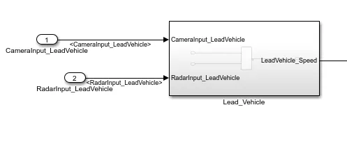
Requirement 1– Lead Vehicle:
- Lead Vehicle is a vehicle which is driving in the road ahead of our drive vehicle.
- Two input signals (Signal Name: CameraInput_LeadVehicle & RadarInput_LeadVehicle).
- Ideally sensor fusion techniques will be deployed to process & analyze data from camera & radar. For complexity reasons, let’s not adapt to any such algorithms.
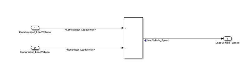
- We can simply add both the radar & camera inputs & the corresponding output is read as Speed profile output (Signal Name: LeadVehicle_Speed).
- Speed data of the lead vehicle is critical in implementing the Adaptive Cruise Control algorithm.
Sub system of Lead_Vehicle model in its input 1 camera input_LeadVehicle & input 2 Radar input_LeadVehicle given to the addition block and the output of the addition block is LeadVehicle _speed as shown below.
Requirement 2 – Drive Vehicle:
- Drive Vehicle is the vehicle driven by the user & this is the vehicle which has ACC algorithm in it.
- Like the Lead Vehicle, Drive Vehicle algorithm also has 2 input signals (Signal Name: CameraInput_DriveVehicle, RadarInput_DriveVehicle) & one signal coming as an Input to this subsystem (Signal Name: Acceleration_Mode) – three inputs into this requirement in total.
- Like the above requirement, sensor fusion techniques will also be deployed here, for complexity reasons we are ignoring them.
- Two output signals come from this subsystem (Signal Name: DriveVehicle_Speed & LeadVehicle_Detected).
- Signal DriveVehicle_Speed is summation of three input signals mentioned above & LeadVehicle_Detected is renamed from Input Signal RadarInput_DriveVehicle by mere use of Signal Conversion block.
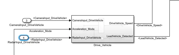
We can draw the vehicle siubstem In the Drive_Vechile sub system has oneof the input is camerainput_drive Vehicle and second Acceleration_mode and Radarinput_DriveVehcle and which are connected to the add block and output of add block is Drive_Vehicle Speed and radarinput_ DriveVehicle is connected to solver connector and which give the input as same output and then connected the output to ACC_ logic to input as shown below.
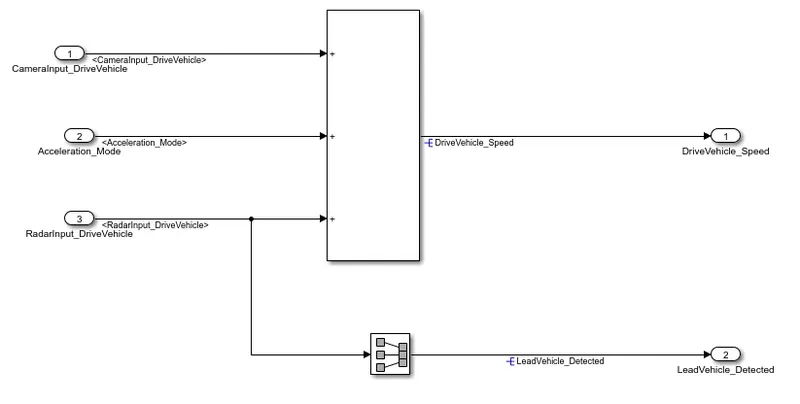
Here we are using signal conversion block, It can Convert a signal to a new type without altering signal values.
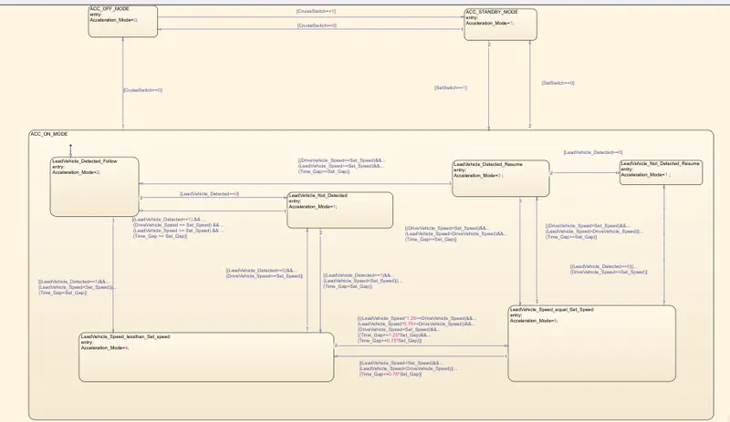
Requirement 3c – ACC ON MODE state logic:
This state will be activated when input signal SetSwitch is equal to 1. There are 6 sub states to this state logic:
They are:
- LeadVehicle_Detected_Follow (Default)
- LeadVehicle_Not_Detected
- LeadVehicle_Detected_Resume
- LeadVehicle_Not_Detected_Resume
- LeadVehicle_Speed_lessthan_Set_Speed
- LeadVehicle_Speed_equal_Set_Speed
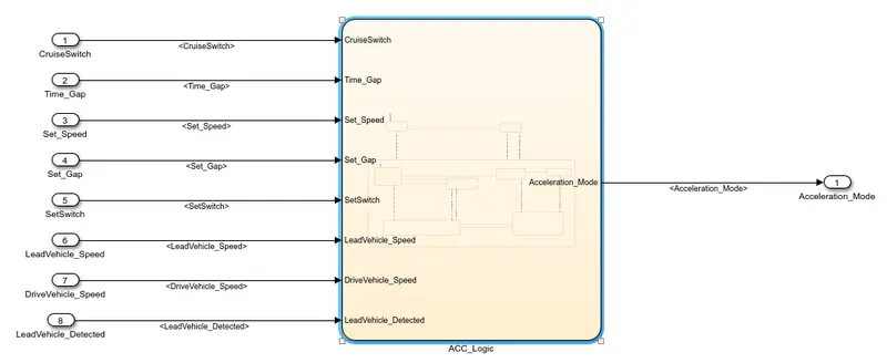
After ACC_Algoritm model we have to creat the the flow chart sheet in that select the all the chart blocks and write the condition for each signal and its create the input and output sequence as per the input data as shown below.
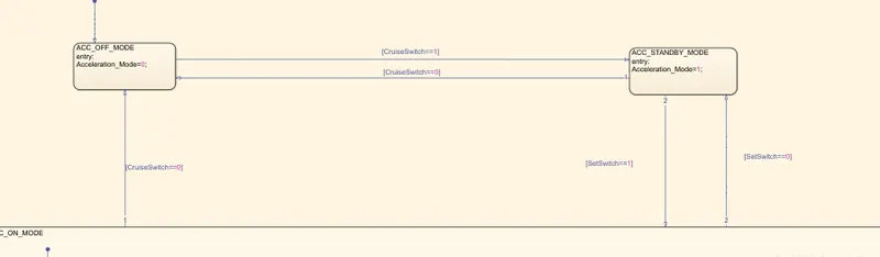
In this ACC_Logic we can create the state flow diagram for the full of transitions and conditions are to be applied in the given system.
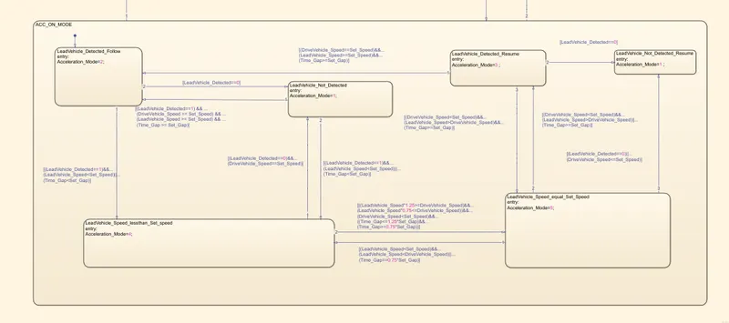
After create the statechart we can giving the value of input and output signals so we can add the signals we use the symbols pane block in modelling
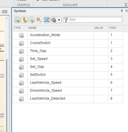
So here we have 8 inputs and 1 out put is taken.After given the input and outport in the chart sampler and the out of flow chart appear as shown below.
Requirement 3c (i) – LeadVehicle_Detected_Follow (ACC ON MODE):
- This is the default sub state inside ACC ON MODE state. Output signal Acceleration_Mode is equal to 2.
- Condition to transit from LeadVehicle_Detected_Follow to LeadVehicle_Not_Detected; Input signal condition LeadVehicle_Detected == 0.
- Condition to transit from LeadVehicle_Detected_Follow to LeadVehicle_Speed_lessthan_Set_Speed; Input Signals condition (LeadVehicle_Detected == 1) && (LeadVehicle_Speed < Set_Speed) || (Time_Gap < Set_Gap).
Requirement 3c (ii) – LeadVehicle_Not_Detected (ACC ON MODE):
- Output signal Acceleration_Mode is equal to 1.
- Condition to transit from LeadVehicle_Not_Detected to LeadVehicle_Detected_Follow; Input signals condition [(LeadVehicle_Detected==1) && (DriveVehicle_Speed == Set_Speed) && (LeadVehicle_Speed >= Set_Speed) && (Time_Gap >= Set_Gap)]
- Condition to transit from LeadVehicle_Not_Detected to LeadVehicle_Speed_lessthan_Set_Speed; Input signals condition [(LeadVehicle_Detected == 1) && (LeadVehicle_Speed < Set_Speed) || (Time_Gap < Set_Gap)]
Requirement 3c (iii) – LeadVehicle_Detected_Resume (ACC ON MODE):
- Output signal Acceleration_Mode is equal to 3.
- Condition to transit from LeadVehicle_Detected_Resume to LeadVehicle_Detected_Follow; Input signals condition [(DriveVehicle_Speed == Set_Speed) && (LeadVehicle_Speed >= Set_Speed) && (Time_Gap >= Set_Gap)]
- Condition to transit from LeadVehicle_Detected_Resume to LeadVehicle_Not_Detected_Resume; Input signal condition LeadVehicle_Detected==0.
- Condition to transit from LeadVehicle_Detected_Resume to LeadVehicle_Speed_equal_Set_Speed; Input Signal condition [(DriveVehicle_Speed < Set_Speed) && (LeadVehicle_Speed > DriveVehicle_Speed) && (Time_Gap >= Set_Gap)]
Requirement 3c (iv) - LeadVehicle_Not_Detected_Resume (ACC ON MODE):
- Output signal Acceleration_Mode is equal to 1.
Requirement 3c (v) - LeadVehicle_Speed_lessthan_Set_Speed (ACC ON MODE):
- Output signal Acceleration_Mode is equal to 4.
- Condition to transit from LeadVehicle_Speed_lessthan_Set_Speed to LeadVehicle_Not_Detected; Input signal condition [(LeadVehicle_Detected == 0) && (DriveVehicle_Speed == Set_Speed)]
- Condition to transit from LeadVehicle_Speed_lessthan_Set_Speed to LeadVehicle_Speed_equal_Set_Speed; Input signals condition [((LeadVehicle_Speed*1.25>=DriveVehicle_Speed) && (LeadVehicle_Speed * 0.75<=DriveVehicle_Speed)) && (DriveVehicle_Speed < Set_Speed) && ((Time_Gap<=1.25*Set_Gap) && (Time_Gap >=0.75*Set_Gap))]
Requirement 3c (vi) - LeadVehicle_Speed_equal_Set_Speed (ACC ON MODE):
- Output signal Acceleration_Mode is equal to 5.
- Condition to transit from LeadVehicle_Speed_equal_Set_Speed to LeadVehicle_Not_Detected_Resume; Input signal conditions is [(LeadVehicle_Detected == 0) || (DriveVehicle_Speed <= Set_Speed)]
- Condition to transit from LeadVehicle_Speed_equal_Set_Speed to LeadVehicle_Detected_Resume; Input signal conditions [(DriveVehicle_Speed < Set_Speed) && (LeadVehicle_Speed > DriveVehicle_Speed) || (Time_Gap >= Set_Gap)]
- Condition to transit from LeadVehicle_Speed_equal_Set_Speed to LeadVehicle_Speed_lessthan_Set_Speed; Input signals conditions [(LeadVehicle_Speed<="" em="">
Here all the conditions are given in the ACC_logic stateflow diagram then we inmplment all the conditions get the diagram like this
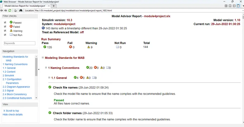
After That we create the model and goto main simulink page in that select model expoler block inthat we have to select the model advisor tool and in that we have to select the model task that we have to select the modeling standards of MAB test has been done.
In this test we are correct and testing model is design as per MAB standards.After run test we have to keep failed as a 0 and warnings is alos keep to be less than 10 as possible to check clear the warnings.
By solving all errors we can generate the report first we can solve the errors by using the MAB standards
First go to the model advisor block in modelling by selecting the task and this task we can only solving the errors by the reference of the MAB standards.
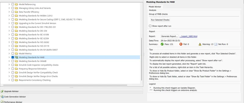
Here we can reducing the errors in to the 9 and after that we can generate the report
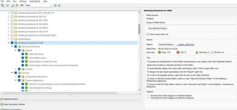
click on the generate report it can download the file
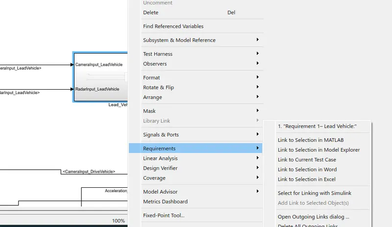
Next open the main model and inside the open the subsystem and add requirements for the Lead_vehicle block by right click on Lead_vehicle block and select the requirements and in that select link to word option and for the reffernce again right click on the block and check requirement 1 showing for lead_ vehicle as shown below.
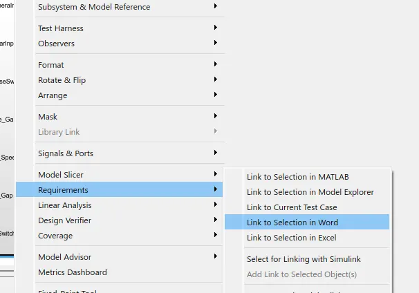
Next open the main model and inside the open the subsystem and add requirements for the Acc_Logic block by right click on Lead_vehicle block and select the requirements and in that select link to word option and for the reffernce again right click on the block and check requirement 3 showing for lead_ vehicle as shown below.
For every blcok we can create the requirement file to the ms word. we have three subsytem is linked with the three requirements of that is linked in word file
we have to the simulink model and it is convert in to the embedded c coder so the main model and in that select the App block and in that select Embeded Code opition and in that C Code select build option and after build the code as shown below.
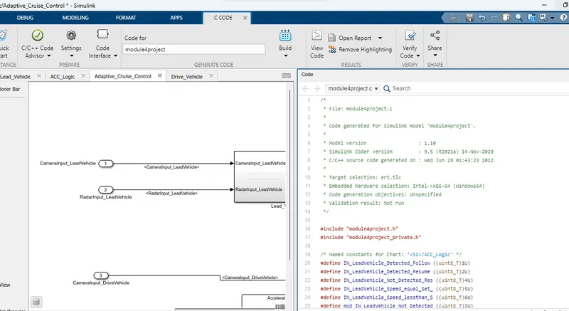
So the Embedded code is generated
CODE :