Project 2 Adaptive Cruise Control
Aim:-
Development of a MATLAB Simulink Model for Adaptive Cruise Control feature as per the requirement document following Model-Based Development (MBD) related processes: SLDD creation, configuration parameter changes, Model advisor check, and code generation using embedded coder tool
Objective:-
1. Creating Adaptive Cruise Control highlight according to the Requirement Document utilizing MATLAB Simulink.
2. Follow all the MBD-related processes: Requirement Tagging and Traceability, SLDD creation, Configuration Parameter changes, Model Advisor check, and Code Generation
. 3. In Configuration Parameters: empower "Backing Floating Numbers" under Code Generation settings.
4. Utilize Embedded Coder to produce the code.
5. In the case of picking code age, Storage class for Input signals: ImportedExtern; Storage class for Output signal: Export to File; Storage class for nearby signals: localizable; Storage class for alignment signals: Const.
6. Pick test time for all signs as 0.01s
Overview:-
Versatile Cruise Control Feature for traveler vehicles permits the host vehicle to adjust to the speed in accordance with the progression of traffic. Driving in weighty rush hour gridlock or holding a protected distance to the first vehicle requires an elevated degree of focus. The Adaptive Cruise Control element can diminish the weight on the driver via consequently controlling the vehicle speed and keeping a predefined least separation from the first vehicle. As a result, the driver appreciates more solace and can focus out and about somewhat better.
A radar sensor is ordinarily at the center of the Adaptive Cruise Control. Introduced at the front of the vehicle, the framework forever screens the street ahead. However long the street ahead is clear, the journey control highlight keeps up with the speed set by the driver. In the event that the framework recognizes a more slow vehicle inside its recognition range, it tenderly decreases speed by delivering the gas pedal or effectively captivating the brake control framework. If the vehicle ahead speeds up or switches to another lane, the journey control naturally advances to the driver's ideal speed. Standard Adaptive Cruise Control can be initiated from rates of around 30 km/h (20 mph) upwards and upholds the driver, principally on cross-country ventures or on expressways. The journey control stops and goes variation is likewise dynamic at speeds under 30 km/h (20 mph). It can keep the set separated from the previous vehicle even at extremely low paces and can decelerate to a total halt. At the point when the vehicle stays halted longer, the driver needs just to reactivate the framework, for instance by momentarily hurrying up the pedal to get back to voyage control mode. Along these lines, voyage control stops and goes upholds the driver even in weighty endless traffic tough situations. Since Adaptive Cruise Control is a solace and comfort framework, brake intercessions and vehicle speed increase just happen inside characterized limits. Indeed, even with Adaptive Cruise Control turned on, it stays the driver's liability to screen the speed and distance from the vehicle in front.
Lead vehicle:-
The lead vehicle is the vehicle that is before our vehicle.
To distinguish the lead vehicle speed, basically added both the radar and camera inputs, and the relating yield is perused as Speed profile yield.
Drive vehicle:-
Drive vehicle is the vehicle which we are driving
To regulate the "Drive Vehicle speed, as per the Requirement Document added Cameralnput. Radarinput & Acceleration Mode feedback from ACC Algorithm.
To detect the Lead vehicle. Radarinput is converted using "Signal Conversion Block To avoid the algebraic error "Unit delay block is used for the Acceleration Mode feedback
ACC Algorithm:-
- Adaptive Cruise Control feature has 3 major modes of operation: OFF Mode. STANDBY Mode & ON Mode.
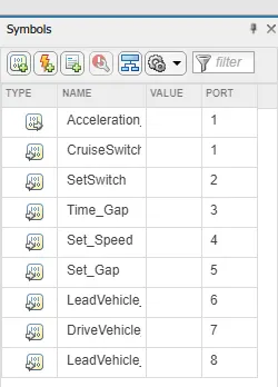
- This particular requirement has to be implemented as state machine logic in Simulink The input signals to the state machine system are (Signal Name Time Gap. Set Speed Set Gap, CruiseSwitch SetSwitch) Also, the output signals (Signal Name DriveVehicle Speed & LeadVehicle Detected) from requirement-2 is fed back as an input signal into this state machine block.
- Additionally, the output signal (Signal Name LeadVehicle Speed) from requirement-1 is given as an input signal to this state machine
- Output from this subsystem is a signal (Signal Name Acceleration Model which governs the vehicular speed of the drive vehicle and automatically adjusts to speed & velocity to match the lead vehicle.
- The rest of the signal developed as per the Requirement.
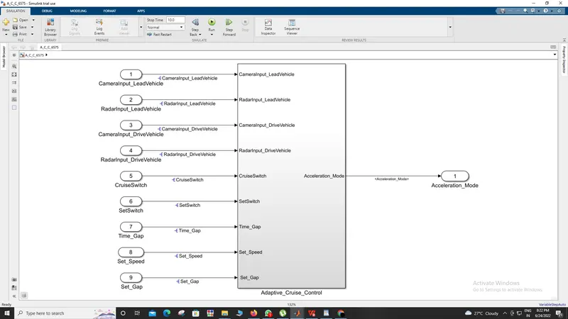
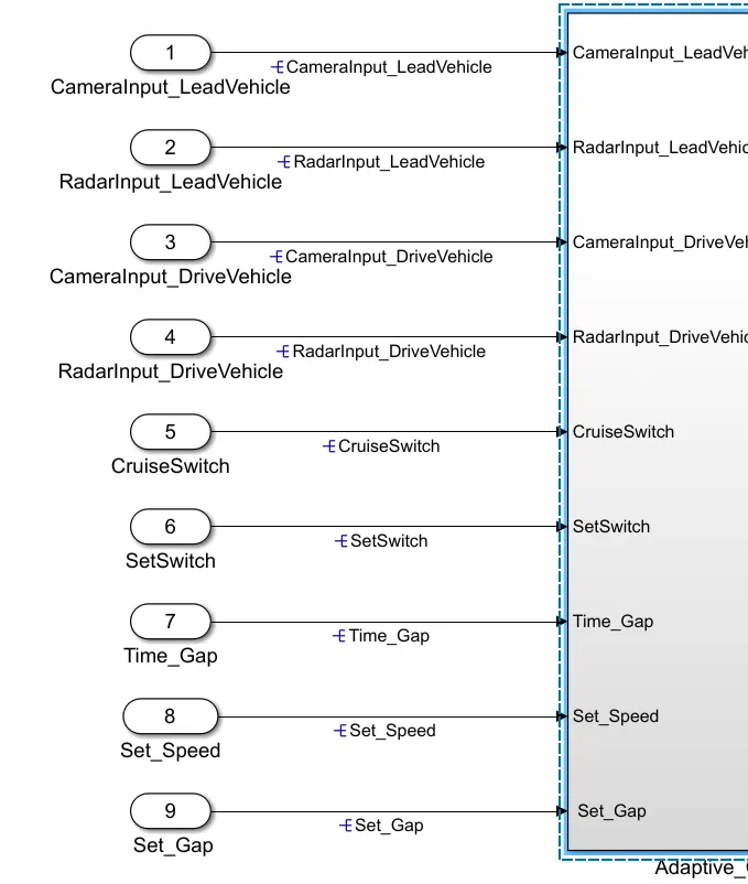
This is the main model subsystem that has
9 inputs CameraInput_LeadVehicle, RadarInput_LeadVehicle, CameraInput_DriveVehicle, RadarInput_DriveVehi, Time_G
Set_Speed, Set_Gap, CruiseSwitch, and SetSwitch enter into the Adaptive Cruise Control subsystem and 1 main
output Acceleration_Mode and other outputs are fed as an input for Stateflow logic
LeadVehicle_Speed, DriveVehicle_Speed, LeadVehicle_Detected
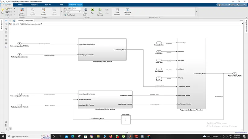
There are 3 requirements each of them is in a separate subsystem.
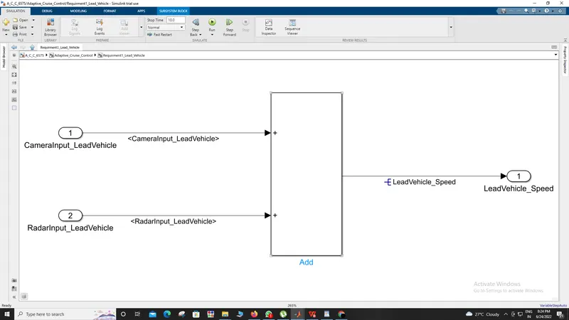
A lead vehicle is a vehicle that is driving on the road ahead of our drive vehicle.
Two input signals (Signal Name: CameraInput_LeadVehicle & RadarInput_LeadVehicle).
Ideally, sensor fusion techniques will be deployed to process & analyze data from cameras & radar. For complexity
reasons, let’s not adapt to any such algorithms.
We can simply add both the radar & camera inputs & the corresponding output is read as Speed profile output
(Signal Name: LeadVehicle_Speed). Speed data of the lead vehicle is critical in implementing the Adaptive Cruise
Control algorithm
Requirement 2 – Drive Vehicle:
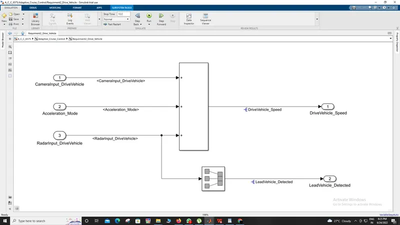
Drive Vehicle is the vehicle driven by the user & this is the vehicle that has an ACC algorithm in it.
Like the Lead Vehicle, the Driver Vehicle algorithm also has 2 input signals (Signal
Name: CameraInput_DriveVehicle, RadarInput_DriveVehicle) & one signal coming as an Input to this subsystem
(Signal Name: Acceleration_Mode) – three inputs into this requirement in total.
Like the above requirement, sensor fusion techniques will also be deployed here, for complexity reasons we are
ignoring them.
Two output signals come from this subsystem (Signal Name: DriveVehicle_Speed & LeadVehicle_Detected).
Signal DriveVehicle_Speed is the summation of three input signals mentioned above & LeadVehicle_Detected is
renamed from Input Signal RadarInput_DriveVehicle by mere use of Signal Conversion block.
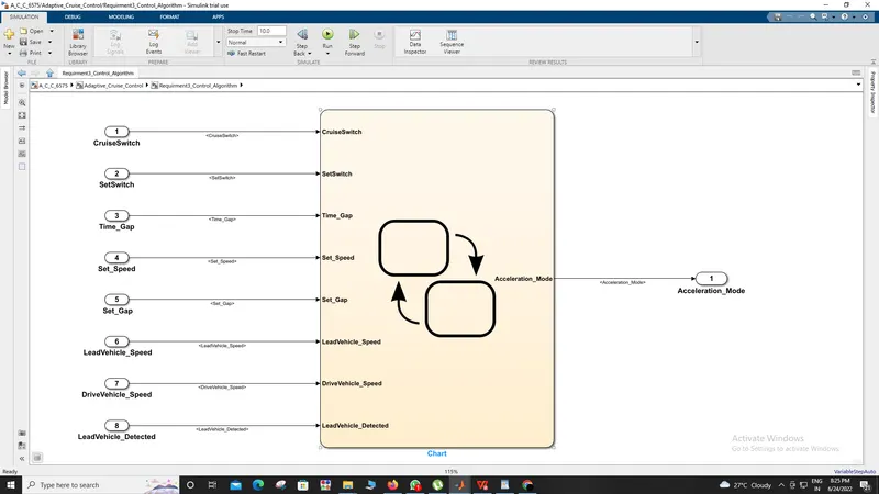
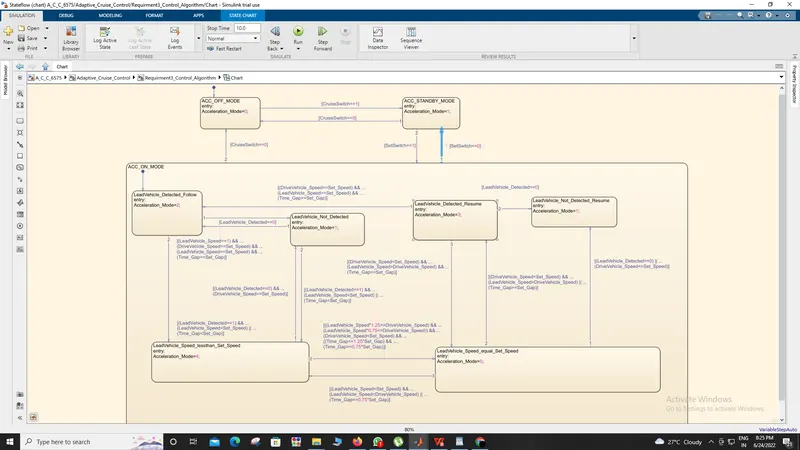
The above figure shows the complete algorithm for the Adaptive Cruise control logic
There are some sub-requirements for the state machine logic
Requirement 3a – ACC OFF MODE state logic:
This is the default state inside state machine logic. Output signal Acceleration_Mode is at value 0 in this state.
This state is governed by the input signal CruiseSwitch. If CruiseSwitch is equal to 1, state ACC STANDBY mode will
get activated.
If CruiseSwitch is equal to 0, state ACC OFF mode will get activated, from either ACC ON mode or ACC STANDBY
mode.
Requirement 3b – ACC STANDBY MODE state logic:
This is the second activated state inside state machine logic. Output signal Acceleration_Mode is at value 1 in this
state.
This state is governed by both input signals CruiseSwitch & SetSwitch. If CruiseSwitch is equal to 1, state ACC
STANDBY mode will get activated.
If CruiseSwitch is equal to 0, state ACC OFF mode will get activated, from either ACC ON mode or ACC STANDBY
mode If SetSwitch is equal to 1, state ACC ON mode will get activated.
If SetSwitch is equal to 0, state ACC STANDBY mode will get activated.
Requirement 3c – ACC ON MODE state logic:
This state will be activated when the input signal SetSwitch is equal to 1. There are 6 sub-states to this state logic: They
are:
LeadVehicle_Detected_Follow (Default)
LeadVehicle_Not_Detected
LeadVehicle_Detected_Resume
LeadVehicle_Not_Detected_Resume
LeadVehicle_Speed_lessthan_Set_Speed
LeadVehicle_Speed_equal_Set_Speed
Requirement 3c (i) – LeadVehicle_Detected_Follow (ACC ON MODE):
This is the default substate inside the ACC ON MODE state.
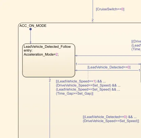
Output signal Acceleration_Mode is equal to 2. Condition to transit
from LeadVehicle_Detected_Follow to LeadVehicle_Not_Detected; Input signal
condition LeadVehicle_Detected == 0.
Condition to transit from LeadVehicle_Detected_Follow to LeadVehicle_Speed_lessthan_Set_Speed; Input Signals
condition (LeadVehicle_Detected == 1) && (LeadVehicle_Speed < Set_Speed) || (Time_Gap < Set_Gap).
Requirement 3c( ii)
Requirement 3c(iii)
Condition to transit from LeadVehicle_Not_Detected to LeadVehicle_Detected_Follow; Input signals
condition [(LeadVehicle_Detected==1) && (DriveVehicle_Speed == Set_Speed) && (LeadVehicle_Speed >=
Set_Speed) && (Time_Gap >= Set_Gap)] Condition to transit
from LeadVehicle_Not_Detected to LeadVehicle_Speed_lessthan_Set_Speed; Input signals
condition [(LeadVehicle_Detected == 1) && (LeadVehicle_Speed < Set_Speed) || (Time_Gap < Set_Gap)]
In this requirement, we have made the algorithm for a Lead vehicle not detected from that I also developed the
algorithm for transit from lead vehicle not detected status to lead vehicle detected status.
If the vehicle is detected by the camera input then it will calculate the Set Gap And time Gap between them and it
will generate the data and fed it into the algorithm.
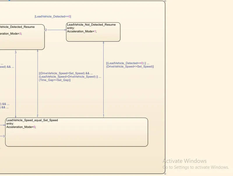
Output signal Acceleration_Mode equal to 3.
Condition to transit from LeadVehicle_Detected_Resume to LeadVehicle_Detected_Follow; Input signals
condition [(DriveVehicle_Speed == Set_Speed) && (LeadVehicle_Speed >= Set_Speed) && (Time_Gap >=
Set_Gap)]
Condition to transit from LeadVehicle_Detected_Resume toLeadVehicle_Not_Detected_Resume; Input signal
condition LeadVehicle_Detected==0.
Condition to transit from LeadVehicle_Detected_Resume toLeadVehicle_Speed_equal_Set_Speed; Input Signal
condition [(DriveVehicle_Speed < Set_Speed) && (LeadVehicle_Speed > DriveVehicle_Speed) && (Time_Gap >=
Set_Gap)]
As the name suggests this stage comes when the lead vehicle is detected by the camera input and it will feed the
data into the algorithm.
Also, it will calculate the distance between the lead vehicle and the drive vehicle and speed of the lead vehicle and
speed of the drive vehicle it analyzes all the data and fed it into the algorithm.
This state will transit from a lead vehicle detected to a lead vehicle not detected if the lead vehicle does not detect
and if it is detected it will transit again and further, it will transit to the next stage which
is LeadVehicle_Speed_equal_Set_Speed.
Output signal Acceleration_Modeis equal to 1.
If the input camera does not detect the lead vehicle then the algorithm will transit in this state after detecting the
vehicle it will transit to another state.
The adaptive cruise control mode will stay active and it will go to desired speed when there is a lead vehicle ahead.
When the lead vehicle is detected by the system it will transit to another state for calculation of the speed and distance
of lead vehicle and also comparing the speed and distance between the lead vehicle and the drive vehicle.
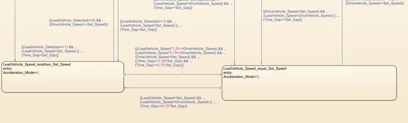
Output signal Acceleration_Mode equal to 4.
Condition to transit from LeadVehicle_Speed_lessthan_Set_Speed to LeadVehicle_Not_Detected; Input signal
condition [(LeadVehicle_Detected == 0) && (DriveVehicle_Speed == Set_Speed)]
Condition to transit from LeadVehicle_Speed_lessthan_Set_Speed
toLeadVehicle_Speed_equal_Set_Speed; Input signals
condition [((LeadVehicle_Speed*1.25>=DriveVehicle_Speed) && (LeadVehicle_Speed *
0.75<=DriveVehicle_Speed)) && (DriveVehicle_Speed < Set_Speed) && ((Time_Gap<=1.25*Set_Gap) &&
(Time_Gap >=0.75*Set_Gap))]
This state will transit in between LeadVehicle_Detected_Follow, LeadVehicle_Not_Detected, and
LeadVehicle_Speed_equal_Set_Speed.
When the lead vehicle is detected by the camera and radar input then it will
from LeadVehicle_Detected_Follow to LeadVehicle_Speed_lessthan_Set_Speed then it will check the speed at
these levels and then it will transit to the next state to match the speed of the drive vehicle for a safe distance.
It will check for the logic and if the logic will match then it will transit to
the LeadVehicle_Speed_equal_Set_Speed.
Requirement 3c (vi) - LeadVehicle_Speed_equal_Set_Speed (ACC ON MODE):
Output signal Acceleration_Mode equal to 5.
Condition to transit from LeadVehicle_Speed_equal_Set_Speed to LeadVehicle_Not_Detected_Resume; Input
signal conditions is [(LeadVehicle_Detected == 0) || (DriveVehicle_Speed <= Set_Speed)]
Condition to transit from LeadVehicle_Speed_equal_Set_Speed toLeadVehicle_Detected_Resume; Input signal
conditions [(DriveVehicle_Speed < Set_Speed) && (LeadVehicle_Speed > DriveVehicle_Speed) || (Time_Gap >=
Set_Gap)]
Condition to transit from LeadVehicle_Speed_equal_Set_Speed
toLeadVehicle_Speed_lessthan_Set_Speed; Input signals conditions [(LeadVehicle_Speed<Set_Speed) &&
(LeadVehicle_Speed<DriveVehicle_Speed) || (Time_Gap == 0.75*Set_Gap)]
This state is the final state where the desired Time gap and the Set gap are obtained and here the drive vehicle will
follow the lead vehicle at the safe distance. And the driver can relax but simultaneously maintain his eye contact
on road but he can do it in a relaxed manner.
TAGGING:-
Requirement Tagging and Traceability report
All the requirements are tagged for better understandability, anyone who is reviewing the model or who is trying to
update the model can get a clear idea of what logic is used in the system. from the requirement manager, we can see
what are all are tagged and the description
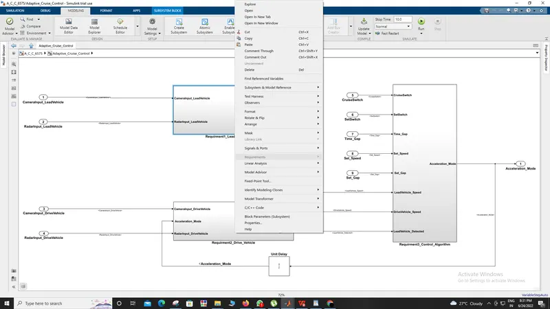
Tagging procedure:
1) Firstly I take new docs of the word and save them as name requirement tagging docs.
2) then I wrote general requirements and the three requirements which are available with the project in word.
3) firstly select general requirements and go on the main model and right-click on it there is the option of requirements then
I click on it and tag it with word docs.
4) also I do this same procedure for requirements 1,requirement2, and requirement3.
DEVELOPING SLDD:-
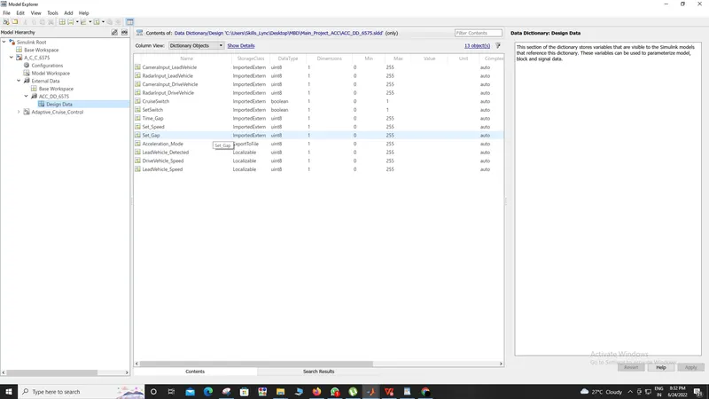
To develop SLDD I went into the modeling tab then I went to model setting then click on external data new then I save
SLDD and create SLDD all the inputs, outputs, calibration parameters are saved in SLDD so while simulation the model it
will take all the values and its parameters from the Simulink Data Dictionary.
Most of them were the signals so I did not add any configuration parameters.
For input signals storage class for Input signals: ImportedExtern; Storage class for Output signal: Export to File; Storage
class for local signals: localizable; Storage class for calibration signals: Const.
And for all the signals we take the sample time as 0.01s.
INPUT-OUTPUT SIGNAL RESOLUTION:
For this signal resolution, I select the signal right click on it go to properties then written signal name and click on shoe
signal name click on ok the signal resolves automatically SLDD. the inputs and output signals are resolved so the signals
will take the values from SLDD and pass them to the logical blocks. Otherwise, it may take some junk values if it is
unresolved.
The Signal has to resolve where it appears for the first time for that I clicked on the signal that has to be resolved right click
on that and then go to properties then click on signal name must resolve to Simulink signal object
Model Update:
The model update is done by Ctrl-D. this is done to check for any static errors. If no errors are coming the model is
working fine without any errors.
Simulation:
The model is simulated too for checking for errors and warnings
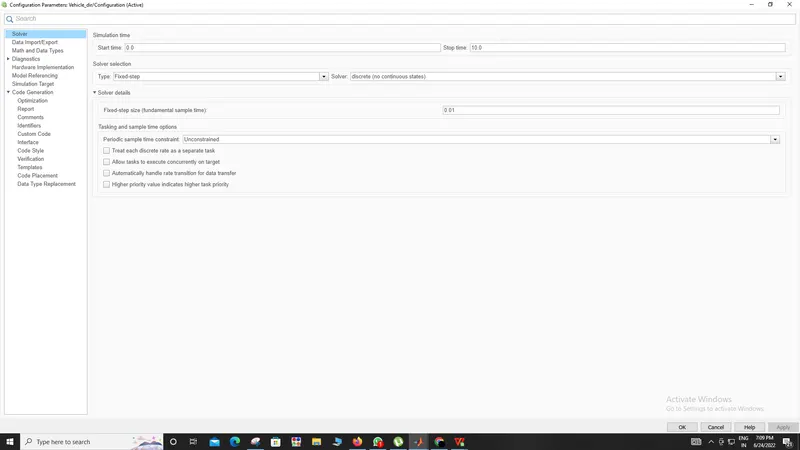
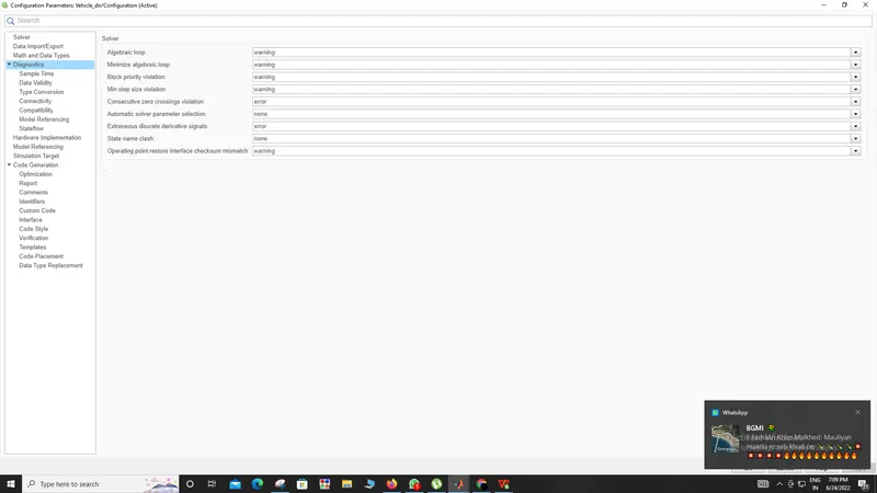
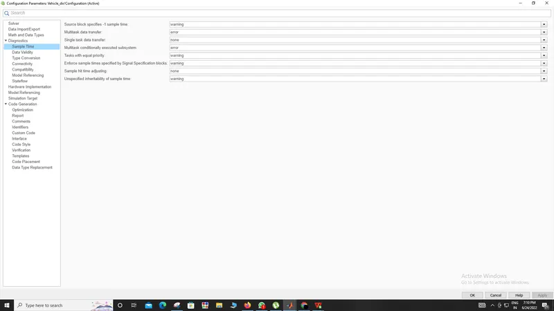
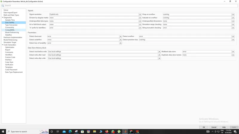
Configuration Parameter Update:
Various configuration parameters are updated as per the code generation the solver type should be fixed for code
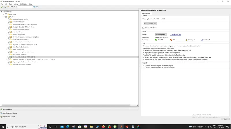
Model Advisory Report:
By running the model advisor tool, we can see commonly made modeling errors.
For the model advisory report, I went into Modeling clicked on model advisor then I choose by product and click on MAB
then click on the check box show report after a run then clicked on run selected checks and I got the report as follows:
CODE GENERATION:-
For generating code I went to APPS then click on embedded coder and click on the build button my code was generated
as follows I attached screenshots of my code and separately code written in the c window as follows:
/*
 * Trial License - for use to evaluate programs for possible purchase as
 * an end-user only.
 *
 * File: A_C_C_6575.c
 *
 * Code generated for Simulink model 'A_C_C_6575'.
 *
 * Model version                  : 1.5
 * Simulink Coder version         : 9.5 (R2021a) 14-Nov-2020
 * C/C++ source code generated on : Fri Jun 24 20:41:50 2022
 *
 * Target selection: ert.tlc
 * Embedded hardware selection: Intel->x86-64 (Windows64)
 * Code generation objectives: Unspecified
 * Validation result: Not run
 */

#include "A_C_C_6575.h"
#include "A_C_C_6575_private.h"

/* Named constants for Chart: '<S4>/Chart' */
#define A_C_C_6575_IN_ACC_OFF_MODE     ((uint8_T)1U)
#define A_C_C_6575_IN_ACC_ON_MODE      ((uint8_T)2U)
#define A_C_C_6575_IN_ACC_STANDBY_MODE ((uint8_T)3U)
#define A_C_C_6575_IN_NO_ACTIVE_CHILD  ((uint8_T)0U)
#define A_C_IN_LeadVehicle_Not_Detected ((uint8_T)3U)
#define IN_LeadVehicle_Detected_Follow ((uint8_T)1U)
#define IN_LeadVehicle_Detected_Resume ((uint8_T)2U)
#define IN_LeadVehicle_Not_Detected_Res ((uint8_T)4U)
#define IN_LeadVehicle_Speed_equal_Set_ ((uint8_T)5U)
#define IN_LeadVehicle_Speed_lessthan_S ((uint8_T)6U)

/* Block states (default storage) */
DW_A_C_C_6575_T A_C_C_6575_DW;

/* External outputs (root outports fed by signals with default storage) */
ExtY_A_C_C_6575_T A_C_C_6575_Y;

/* Real-time model */
static RT_MODEL_A_C_C_6575_T A_C_C_6575_M_;
RT_MODEL_A_C_C_6575_T *const A_C_C_6575_M = &A_C_C_6575_M_;
real_T rt_roundd_snf(real_T u)
{
  real_T y;
  if (fabs(u) < 4.503599627370496E+15) {
    if (u >= 0.5) {
      y = floor(u + 0.5);
    } else if (u > -0.5) {
      y = u * 0.0;
    } else {
      y = ceil(u - 0.5);
    }
  } else {
    y = u;
  }

  return y;
}

/* Model step function */
void A_C_C_6575_step(void)
{
  /* local block i/o variables */
  uint8_T LeadVehicle_Speed;
  uint8_T DriveVehicle_Speed;
  uint8_T LeadVehicle_Detected;
  int32_T tmp;
  int32_T tmp_0;
  uint8_T tmp_1;
  uint8_T tmp_2;

  /* Sum: '<S2>/Add' incorporates:
   *  Inport: '<Root>/CameraInput_LeadVehicle'
   *  Inport: '<Root>/RadarInput_LeadVehicle'
   */
  LeadVehicle_Speed = (uint8_T)((uint32_T)CameraInput_LeadVehicle +
    RadarInput_LeadVehicle);

  /* UnitDelay: '<S1>/Unit Delay' */
  Acceleration_Mode = A_C_C_6575_Y.Acceleration_Mode_e;

  /* Sum: '<S3>/Add' incorporates:
   *  Inport: '<Root>/CameraInput_DriveVehicle'
   *  Inport: '<Root>/RadarInput_DriveVehicle'
   */
  DriveVehicle_Speed = (uint8_T)((uint32_T)(uint8_T)((uint32_T)
    CameraInput_DriveVehicle + Acceleration_Mode) + RadarInput_DriveVehicle);

  /* SignalConversion: '<S3>/Signal Conversion' incorporates:
   *  Inport: '<Root>/RadarInput_DriveVehicle'
   */
  LeadVehicle_Detected = RadarInput_DriveVehicle;

  /* Chart: '<S4>/Chart' incorporates:
   *  Inport: '<Root>/ Set_Gap'
   *  Inport: '<Root>/CruiseSwitch'
   *  Inport: '<Root>/SetSwitch'
   *  Inport: '<Root>/Set_Speed'
   *  Inport: '<Root>/Time_Gap'
   *  UnitDelay: '<S1>/Unit Delay'
   */
  if (A_C_C_6575_DW.is_active_c3_A_C_C_6575 == 0U) {
    A_C_C_6575_DW.is_active_c3_A_C_C_6575 = 1U;
    A_C_C_6575_DW.is_c3_A_C_C_6575 = A_C_C_6575_IN_ACC_OFF_MODE;
    A_C_C_6575_Y.Acceleration_Mode_e = 0U;
  } else {
    switch (A_C_C_6575_DW.is_c3_A_C_C_6575) {
     case A_C_C_6575_IN_ACC_OFF_MODE:
      A_C_C_6575_Y.Acceleration_Mode_e = 0U;
      if (CruiseSwitch) {
        A_C_C_6575_DW.is_c3_A_C_C_6575 = A_C_C_6575_IN_ACC_STANDBY_MODE;
        A_C_C_6575_Y.Acceleration_Mode_e = 1U;
      }
      break;

     case A_C_C_6575_IN_ACC_ON_MODE:
      if (!SetSwitch) {
        A_C_C_6575_DW.is_ACC_ON_MODE = A_C_C_6575_IN_NO_ACTIVE_CHILD;
        A_C_C_6575_DW.is_c3_A_C_C_6575 = A_C_C_6575_IN_ACC_STANDBY_MODE;
        A_C_C_6575_Y.Acceleration_Mode_e = 1U;
      } else if (!CruiseSwitch) {
        A_C_C_6575_DW.is_ACC_ON_MODE = A_C_C_6575_IN_NO_ACTIVE_CHILD;
        A_C_C_6575_DW.is_c3_A_C_C_6575 = A_C_C_6575_IN_ACC_OFF_MODE;
        A_C_C_6575_Y.Acceleration_Mode_e = 0U;
RESULT AND CONCLUSION:-
With the assistance of the MATLAB Simulink apparatus, I had the option to make the Adaptive Cruise control model, made the Stateflow rationale for the model, run the model warning to check for the MAB rules lastly produce the C code out of the model. I took in the previously mentioned device in this task and had the option to execute the necessity report rationale