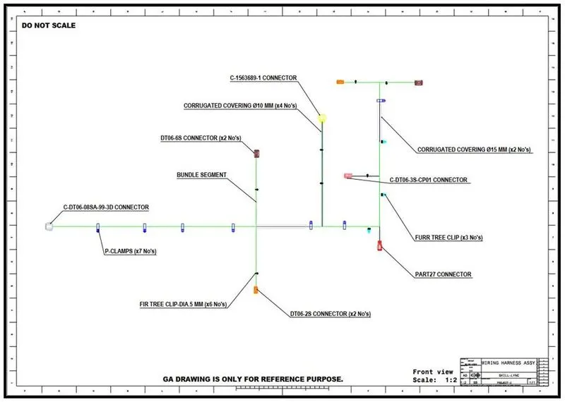
Project 2
Electrical Wiring Harness Design using CATIA
Wiring Harness Design, Routing and Flattening for Vehicle Backdoor.
The Harness assembly to be flattened in the “flattening harness” workbench is for Vehicle Backdoor as shown in below diagram,
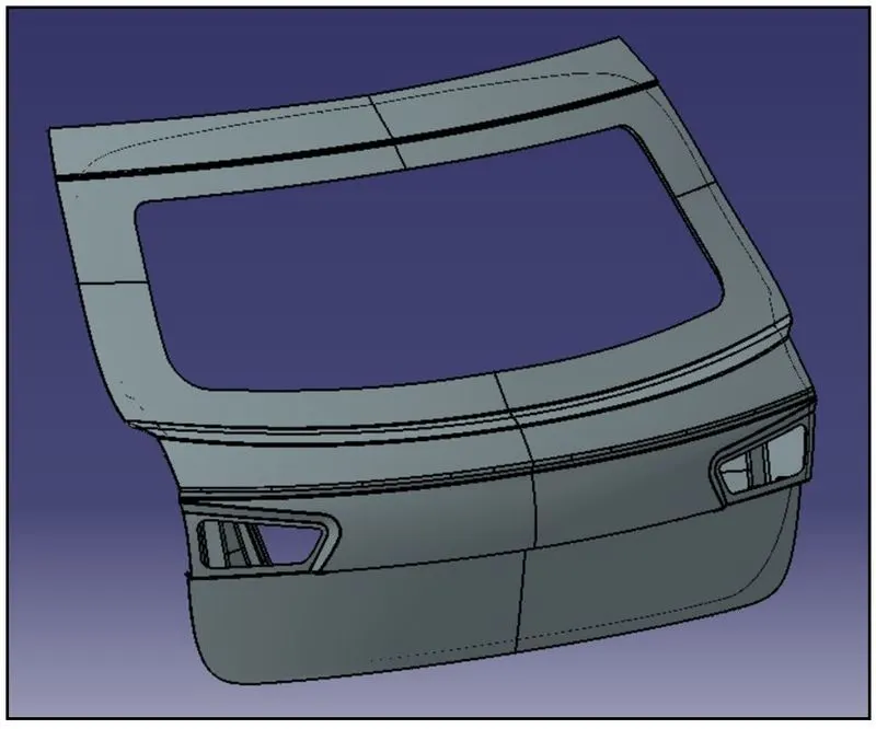
The above Backdoor consists of two panels, one is outer panel and another one is the inner panel.
For the given, Backdoor part, we have to create the wiring harness assembly on the inner panel.
By selecting the required no. of connectors and necessary mounting supports, the wiring bundle segments are to be created.
The Harness assembly for the above Vehicle Backdoor is saved in a new product file, which consists of the subassemblies as shown below,
- Geometrical Bundle: - The Geometrical Bundle consists all the connectors, and its respective geometrical parameters.
- Multi-Branchable Document: - The Multi-Branchable document consists of all the Bundle segments and protective coverings used to connect the connectors to create the harness assembly as per the above diagram.
- Publications: - All the electrical data gets saved in the Publications for establishing the electrical parameters.
- CONNECTOR DEFINITION.
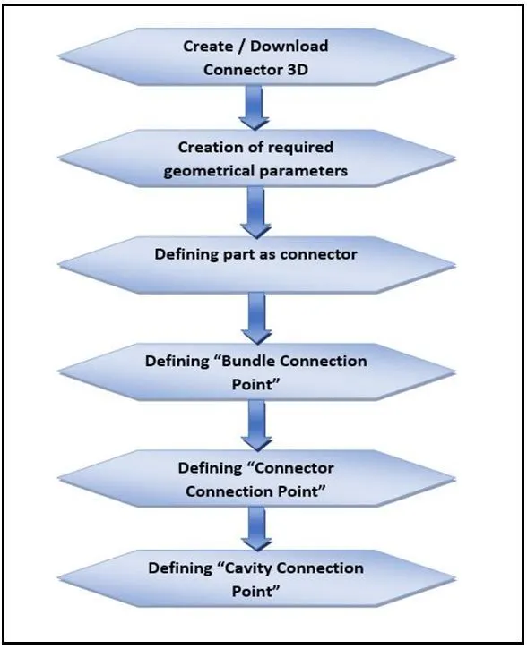
The Connectors to be defined electrically are to be created or 3D part file is to be downloaded from the respective websites.
The process for connector definition in CATIA is shown below,
- Connectors Assembly in Vehicle Backdoor
The Electrically Defined Connectors are to be assembled in the Vehicle Backdoor for Routing the Bundle segments.
The assembled view of Connectors in the Vehicle Backdoor is shown in below diagram,
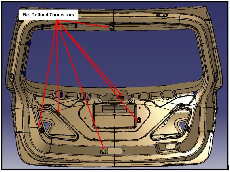
Once, the electrically defined connectors are placed in their respective places, then the Mounting equipment’s are assembled in the Vehicle Backdoor.
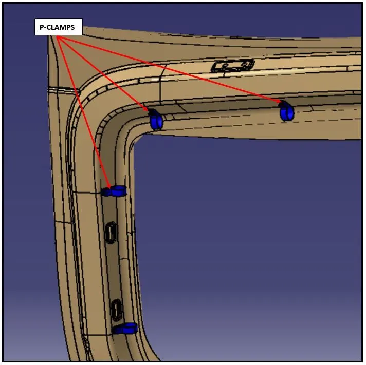
The Mounting Equipment’s mainly helps to support the bundle segment and proper orientation of the bundles during the routing process.
A properly oriented bundle assembly ensures that its function is not affected by the external contributing factors, like direct contact of the bundle segment to the high temperature surface, which can be prevented by providing the necessary supports/mounting equipment’s at right place thus, maintaining the right clearance without getting affected.
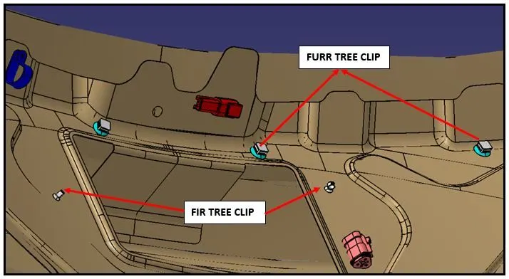
The Minimum supports/mounting equipment’s considered for the Vehicle Backdoor are as follows,
- P-CLAMPS.
- FURR TREE-CLIP.
- FIR TREE-CLIP.
- Bundle Routing of connectors in electrical harness assembly workbench.
Preparation of harness assembly
The Wiring harness product assembly contains the following components,
- The harness context assembly.
- Geometrical Bundle.
- Electrical Bundle.
- The harness context assembly: -
The Harness context assembly is the top-level product file that contains the harness geometrical bundle and the wire harness electrical bundle.
- Geometrical Bundle: -
Geometrical bundle is the sub level product which contains all of the harness components. i.e., clips, supports, splices, grommets, annotation and actual physical bundle segments and branches.
- Electrical Bundle: -
Electrical Bundle is a sub-product file, which contains all of the electrical circuit information.
- Defining of the wire harness routing.
Conditions to be adhered for wiring harness routing is shown below,
- Geometrical Bundle assembly is to be completed.
- All components are placed at desired locations.
- All type of electrical connections/constraints are defined.
- Background Geometry Data is available and assembled in Geometrical bundle context assembly.
- All clips / clamps /channels are placed at desired locations.
Considering all the criteria mentioned above, we have to complete the bundle routing process, covering all the connectors connected electrically by the created bundle segments.
In the Geometrical Bundle sub-product file, we have to create a “Multi-Branchable” file for creating and placing all the bundle segments.
The necessary branch points are added in the bundle segments, to create the sub-branches for connecting the connectors surrounded near to the branch point
The suitable bend-ratio and slack values are to be provided as a input for creation of bundle segments. We have to note carefully, that excess slack is avoided, as it may lead to tangled condition of bundle segments in the Vehicle Backdoor, when the vehicle is in movement.
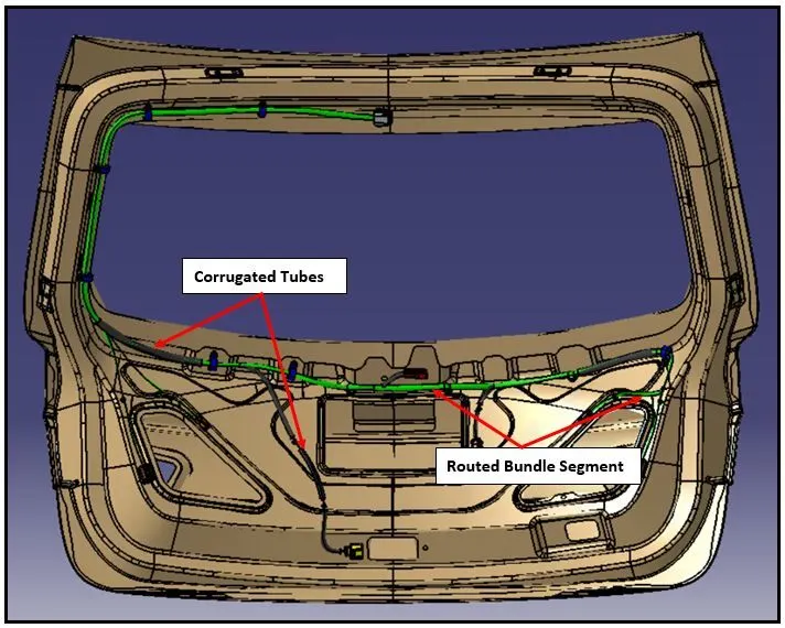
There are protective coverings provided to certain bundle segments. The protective coverings used for the bundle segments is ‘CORRUGATED TUBES’.
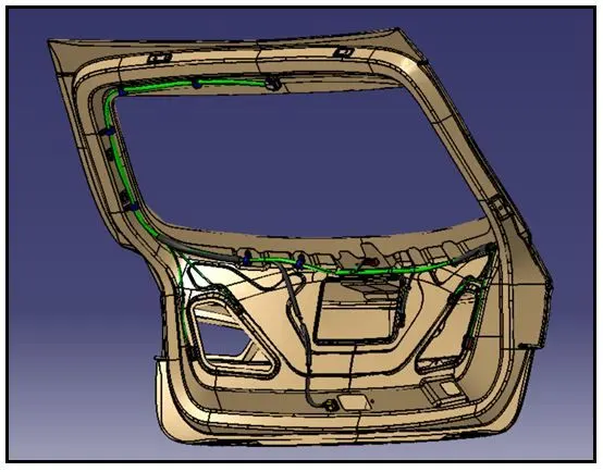
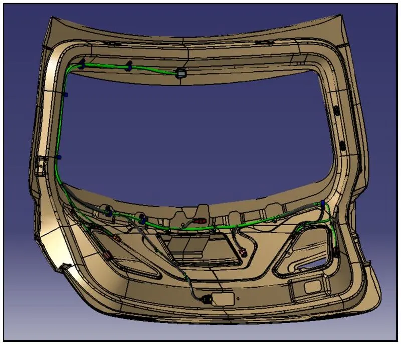
The fully completed bundle routing for Vehicle Backdoor is shown in below diagram,
- Bundle Continuity check for Routed Wiring assembly
Once the Routing of the bundle segments is completed, then the Bundle continuity check is done to ensure that all the connectors are fully connected with the bundle segment and no discontinuity is observed.
The discontinuity in the bundle assembly may lead to incomplete circuit, resulting in functional failure.
The “Geometrical Bundle” assembly completed on Vehicle Backdoor is shown in below diagram,
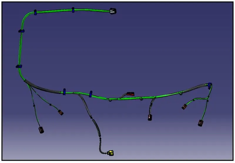
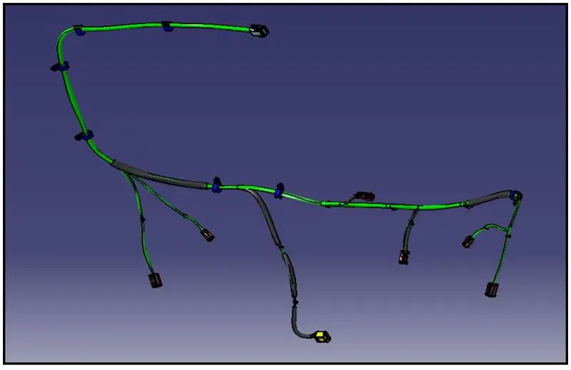
For the above bundle assembly, the continuity check is done by using the “Search” command in CATIA which is available in ’EDIT’ option present in toolbar.
The “Search” command has a sub-option named “advanced”, which helps to filter certain conditions helping to check the bundle continuity for the above geometrical bundle assembly.
The Composed Query in Advanced search has the logical condition which helps to know, whether the connectors are connected electrically with the bundle segments.
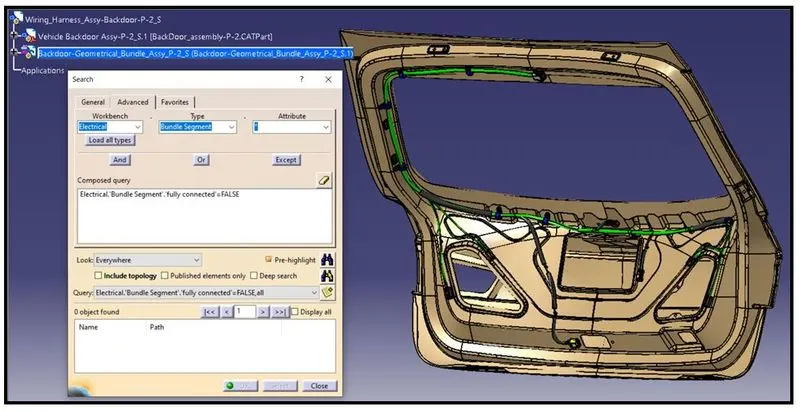
The above bundle continuity check for geometrical bundle assembly has passed the logical condition of “fully connected = FALSE”, thus indicating that all the bundle segments are connected with no discontinuity.
The “FALSE” condition indicates that, there are no bundles segments that are disconnected. The results obtained after the analysis conducted also indicates that, there are “0 (Zero) objects” found, which clearly depicts fully connection of bundle segments with the electrically defined connectors is achieved successfully.
- Electrical Wiring Harness Flattening
The Flattening of the wiring harness assembly has to be initiated prior to setting of the flattening harness parameters in the flattening harness workbench in CATIA.
The Flattening harness parameters mainly includes the selection of “PLANE/FACE OF THE OBJECT” to view the harness assembly and make changes to the flattened bundles with respect to the selected PLANE OF VIEW.
The Second most important in Flattening harness parameter is representation of the flattened view in drawing sheet, such that the different parts of the wiring harness bundle assembly are identifiable with respect to the electrical schematic diagram for parts like bundle segments, connectors and protective coverings.
The Main Flattening harness parameters to be set are shown below,
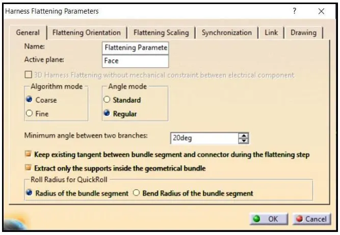
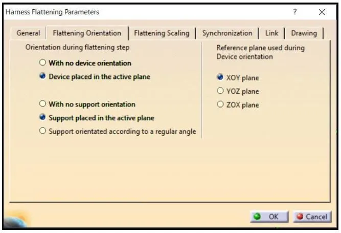
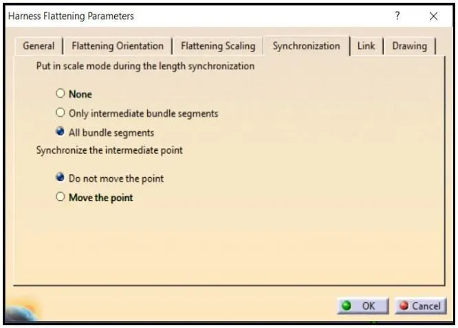
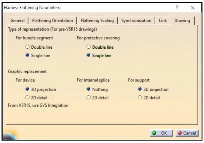
Once the flattening parameters are set then, a flattening harness file gets created in the flattening harness workbench.
We have to now select the respective harness assembly for which flattening process has to be executed.
The following steps given below, explains the steps for flattening the harness assembly,
- Keeping the flattening harness file opened in the CATIA window, we have to next open the harness assembly file, for which flattening has to be done.
- Next, we have to make both the file to be opened in vertical windows, in order to extract the harness assembly from the harness assembly file to flattening work bench, where the harness assembly will be flattened.
- We have to select the extract command in flattening workbench and select the harness assembly product file to make the harness assembly transferred to flattening workbench, along with its all-defined supports.
- Once the extraction of the harness assembly file to flattening workbench is completed, then the harness assembly file gets a file extension ending with “Ehf”.
- In the Flattening workbench, we have to select the flatten command and make the respective harness assembly flattened meeting with the set flattening parameters, which were defined prior to extracting of the harness assembly file.
- In the Flattening workbench, there are major commands used to represent the flattened harness assembly in accordance with the electrical schematic diagram. The commands used are: - “Rotate”, “Quick-roll”, “Straighten”, “Arrange junction” etc.
The Flattened procedure performed for the harness assembly is shown in below figure,
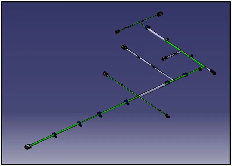
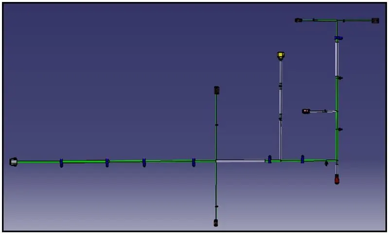
“Synchronization” command available in the flattening workbench is used after the finalization of the flattened orientation of bundle segments.
The “Synchronization” command pops out a small window, which asks to select the necessary parameters that are to be synchronized for the flattened bundle assembly with respect to the geometrical bundle assembly.
Any changes like addition / deletion of components of bundle assembly in “geometrical bundle assembly” file gets reflected on the “flattening assembly file”, after the synchronization process is completed.
“Synchronization” is a very important process, as the flattened view represents the replicative of the “geometrical bundle assembly”.
- Electrical Wiring Harness Flattened view representation in 2D Drawing sheet
The Drawing of flattened view of harness assembly is illustrated by representing the “BUNDLE” segments in 2D-LINE, whereas the Connectors, Mounting equipment and P-Clamps in 3D-DETAIL.
The View of the flattened harness assembly will be normal to the face selected on connector.
The necessary annotations to the parts, BOM display and other detailing’s are provided on to the drawing.