Project 2
Description:
As discussed in Lecture 11, Project 2 deals with the development of a forward energy-based fuel consumption model of a P1 hybrid vehicle. This model is based on the conventional vehicle model from Project 1.
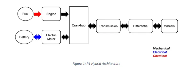
The main goal of this project is to understand the functionality of a P1 hybrid and be able to model it.
Honda Insight motor and battery are considered for this project. Data is taken from ADVISOR data base developed by NREL, USA. Data provided in the project files.

“Project2_InitFile.m” is a Matlab script used to load all the variables required for running the Simulink model and for post-processing. The drive cycle selection is also done here. Before running the Simulink vehicle model, run this initialization script.
Task:
The task of this project is to quantify the improvement in fuel economy numbers for the hybrid vehicle (kmpl), compared to the conventional vehicle, on the urban cycle (UDDS) and highway cycle (HWFET). Also, to analyze and understand the vehicle operating points in terms of engine and motor speed, torque, transmission speeds, pedal positions, gear, distance traveled, battery voltage, current, SoC etc.
To do that, the following steps need to be followed:
1) Load the Project2 folder as the Current Folder in Matlab.
2) Run the “Project2_InitFile.m” Matlab script.
3) Copy the Conventional vehicle Simulink model created for Project 1 in this folder. Figure 1: P1 Hybrid ArchitectureHybrid Drives Development
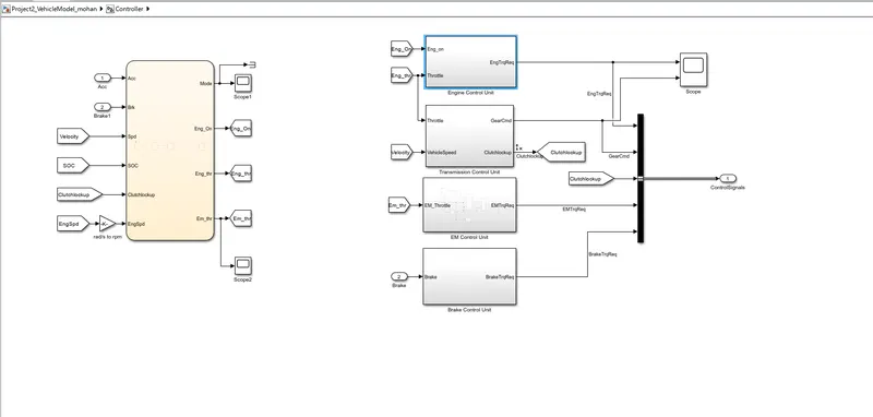
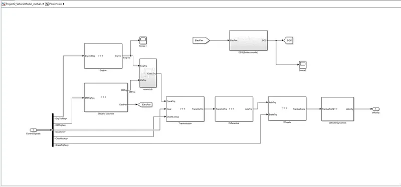
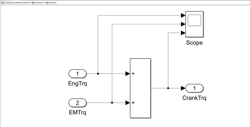
4) Modify this model into a hybrid vehicle model. The lecture presentations can be used as reference. Battery and Supervisory controller models developed in the assignments can be reused.
5) Add additional ‘To Workspace’ blocks for transferring the desired Simulink vehicle data into the Matlab workspace.
6) Simulate the hybrid model on the desired drive cycles.
7) Write a project report that contains the following:
a. Tabulate the fuel economy numbers (kmpl) for UDDS and HWFET cycle. Compare these numbers with the baseline numbers for conventional vehicle model from Project 1.
b. Plot the time trace for engine, transmission input, transmission output and wheel speed on one plot.
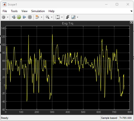
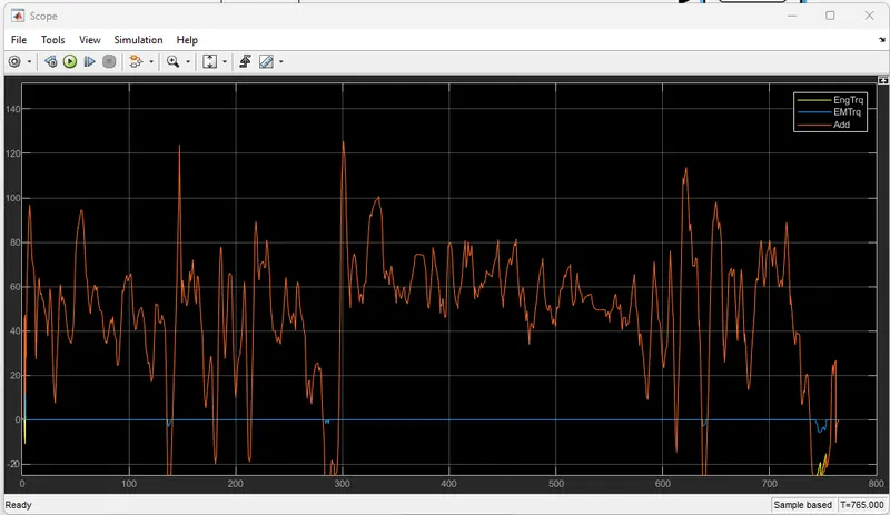
c. Plot engine torque, engine power, fuel rate and fuel consumption using subplots.
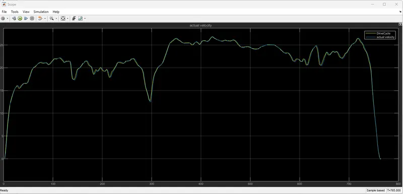
d. Plot accelerator and brake pedal, gear command, vehicle desired and actual speed, vehicle distance using subplots.
e. Plot the engine operating points on the engine fuel map.
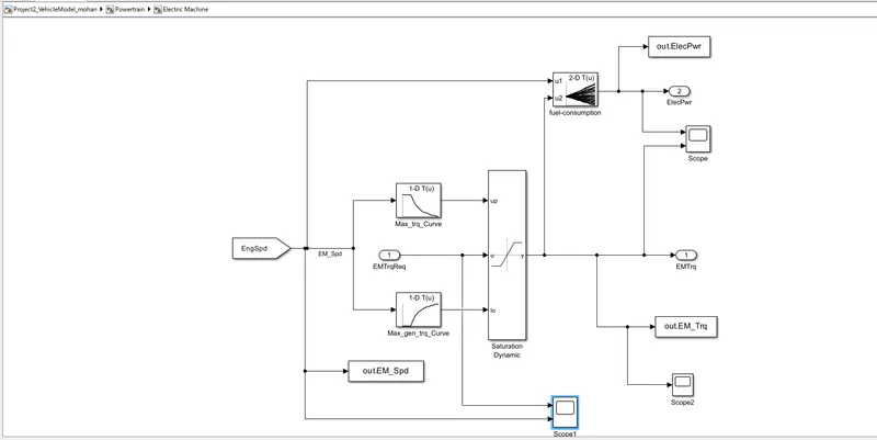
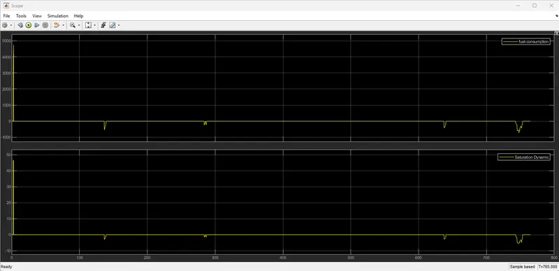
f. Plot motor speed, torque, motor input power using subplots.
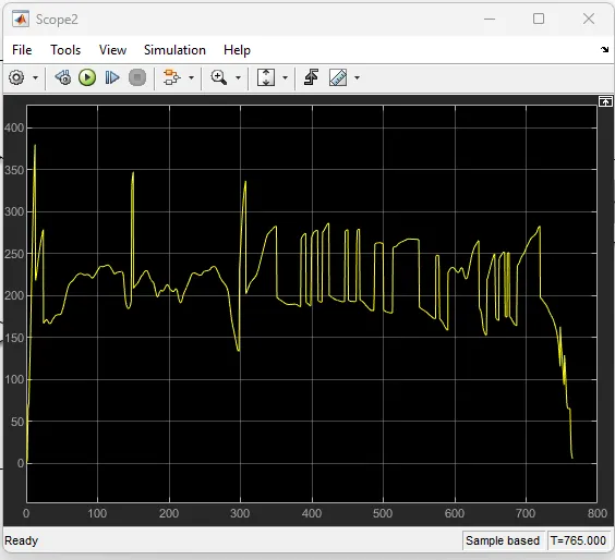
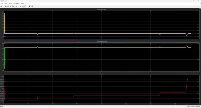
g. Plot pack voltage, current and SoC using subplots.
h. Plot the motor operating points on the motor input power map, with the motor max motoring and generating torque curves.
i. Write down appropriate brief comments on each of these plots, describing the vehicle behavior throughout the drive cycle.
j. Generate the plots for both drive cycles
%ANSWER
AIM: Develop a model for forwarding Energy based fuel consumption model of a P1 type Hybrid Vehicle.
Objectives:
- Tabulate the fuel economy numbers (kmpl) for UDDS and HWFET cycles. Compare these numbers with the baseline numbers for the conventional vehicle model from Project 1.
- Plot the time trace for engine, transmission input, transmission output, and wheel speed on one plot.
- Using subplots, plot engine torque,e power, fuel rat,e, and consumption.
- Plot accelerator and brake pedal, gear command, vehicle desired and actual speed, and vehicle distance using subplots.
- Plot the engine operating points on the engine fuel map.
- Plot motor speed, torque, and motor input power using subplots.
- Plot pack voltage, current, and SoC using subplots.
- Plot the motor operating points on the motor input power map, with the motor max motoring and generating torque curves.
- Write down appropriate brief comments on each of these plots, describing the vehicle behavior throughout the drive cycle.
- Generate the plots for both drive cycles.
Theory of P1 Hybrid:
The P1 architecture, with the electric machine connected directly to the crankshaft, is the solution adopted by Honda on their first generation Integrated Motor Assist (IMA) technology. The electric motor functions as a generator, during vehicle deceleration, as an engine starter, and as a motor (to assist the engine) during vehicle accelerations.
One of the biggest advantages of this solution is that the electric motor can provide higher torque than the BiSG(Belt integrated Starter Generator) since there is no belt limitation (due to slipping). However, since there is no speed/torque ratio between the electric machine and crankshaft, the torque requirements on the electric motor can be quite demanding.
Mild Hybrid Vehicle:
through different system architectures for Mild Hybrid Electric Vehicles (MHEV), looking into the positioning of the components on the vehicle, the possible control functions, and advantages and disadvantages in terms of fuel efficiency and driveability.
To recall the different types of hybrid electric vehicles and what makes a mild hybrid electric vehicle, read the following articles:
- Mild Hybrid Electric Vehicle (MHEV) – introduction
- Understanding micro, mild, full, and plug-in hybrid electric vehicles.
By architecture, topology, or configuration we understand the positioning of the main components of the hybrid electric system on the vehicle. Since the only mechanical link between the electrical system and the rest of the vehicle is done through the electric machine, the MHEV architecture is defined by the position of the electric machine and the type of connection with the powertrain/drivetrain (belt, integrated, or gear mesh).
The 48V electrical system has become the industry standard for mild hybrid MHEV applications for several reasons:
- it’s relatively simple to integrate into a vehicle
- it’s modular, safe, and compact
- the mass of the components is relatively small so the impact on the total weight of the vehicle is limited
- the system cost-to-performance (fuel efficiency, torque boost) ratio is very competitive
Except for the crankshaft-mounted integrated starter generator (Honda IMA and Mercedes Benz BlueHybrid), all the mild hybrid vehicle architectures presented in this article are based on 48V systems.
The powertrain configuration of the MHEV system has a significant impact on the performance and characteristics of the vehicle, in terms of:
- integration cost
- fuel efficiency
- dynamic performance (powertrain torque enhancement)
Automotive OEMs and automotive Tier 1 system suppliers are currently analyzing and evaluating several major powertrain architectures for MHEVs. The electric machine can be positioned, relative to the other powertrain components, in five major points:
Image: MHEV powertrain architectures
A brief description of the electric machine connection points is done in the table below.
P0 Hybrid:
The electric machine is connected with the internal combustion engine through a belt, on the front end accessory drive (FEAD)
P1 Hybrid:
The electric machine is connected directly to the crankshaft of the internal combustion engine
P2 Hybrid:
The electric machine is side-attached (through a belt) or integrated between the internal combustion engine and the transmission; the electric machine is decoupled from the ICE and it has the same speed as the ICE (or multiple of it)
P3 Hybrid:
The electric machine is connected through a gear mesh with the transmission; the electric machine is decoupled from the ICE and its speed is a multiple of the wheel speed.
P4 Hybrid:
The electric machine is connected through a gear mesh on the rear axle of the vehicle; the electric machine is decoupled from the ICE and it’s located in the rear axle drive or the hub of the wheel.
Thesis:
Forward-Modelling of Vehicle Approach:
- This kind of approach is known as the cause-effect, engine-to-wheel or rear-to-front method, the direction of calculation is the same as the direct positive power flow method: power flow is from the engine to the wheel.
- This approach is based on the vehicle dynamics equation and the behavior of single powertrain components and their dynamic interaction between the wheels.
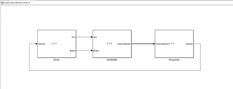
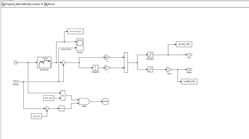
- A Driver Controller is required to control the vehicle to follow desired speed and to calculate.
- The Controller is implemented to model that the driver will either push the accelerator or the brake pedal to match the desired speed which enables to study the braking of the vehicle
- It also acts as a feedback loop for the vehicle which was used to determine the energy requirements to drive the vehicle.
3 Stages to Compute the Simulation:
- Pre-Processing
- Run the Simulink Model
- Post-Processing
Project2_InitFile