Project 2
1. Design an interleaving DC/DC converter system for a data centre application with the following specifications:
• Input voltage: 45 – 60 v
• Output voltage: 3 V
• Output current: 100A
• Efficiency > 85% (extra credit for efficiency higher than 90% on a spice-based software simulation tool)
Requirements:
1) Show your design in detail (most probably, you will need to use an isolated system to achieve this low voltage conversion ratio, you might also need to use a multiphase system to increase the efficiency).
2) Show the input voltage, the output voltage, the input current, the output current, the system efficiency, and any other simulation plots necessary to evaluate your design.
Given Data:
1. Input voltage: 45 - 60 v
2. Output voltage: 3 V
3. Output current: 100A 4. Efficiency > 85%
Assumations:
1. Switching frequency= 20000H
2. Duty ratio=0.5
Calculations:
For this design we are using the Forward converter formulas:
1) Duty cycle:
Vo/Vin = D* N₂/ N₂₁
Let's assume that we will design for 50% Duty ratio:
N₂/N₁ = 0.1
These we chose the following:
N1= 500
N2=50
2) Since we chose D=0.5 then using equation we found that,
D(1 + N3/N1) <1
thus N3/N1< 1
Thus we will choose,
N3= 150 turns
3) Now, we will choose a an inductor for 40% current ripple:
R= Vo^2/P = 0.03
IL = Vo / R = 100 A
L = Vo/Fs*delIL (1-D)
L = 1.5e^-6
4) NOw we are calculate the capacitor.
C = 1-D/8L*FS^2(delVo/Vo)
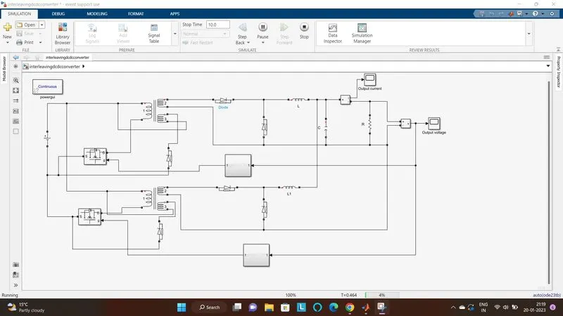
From all the above All calculation we are model now the interleaving DC/DC converter:
The recent development of battery-powered applications is improving the need of efficient step-up dc-dc converters Nowadays, step up conversion is widely used in many applications like Electric vehicles, Photovoltaic (PV) systems, Uninterruptible power supplies (UPS), and fuel cell systems. By paralleling the converters, the input current can be shared among inductors so that high reliability and efficiency in power electronic systems can be obtained. In this paper, the conventional boost dc-dc converter and interleaved boost dc-dc converter are simulated using MATLAB/SIMULINK and MULTISIM software. The converters are tested by varying the input voltage with a constant duty cycle in Continuous Conduction Mode (CCM). The performance parameters of the converters are compared. The converters are controlled by interleaved switching signals, which have the same switching frequency but the shift in phase. Using interleaved converter we can get improved efficier sy, reduced ripple voltage, reduced inductor current ripple, fast switching speed.
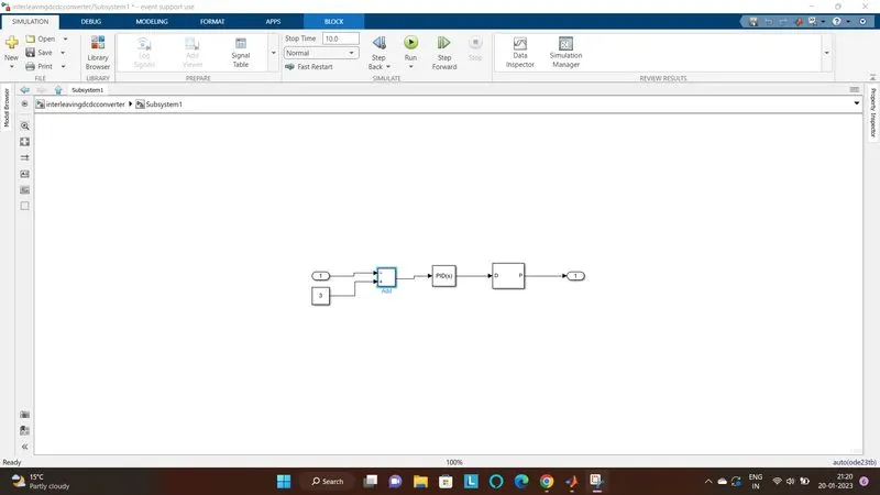
PID
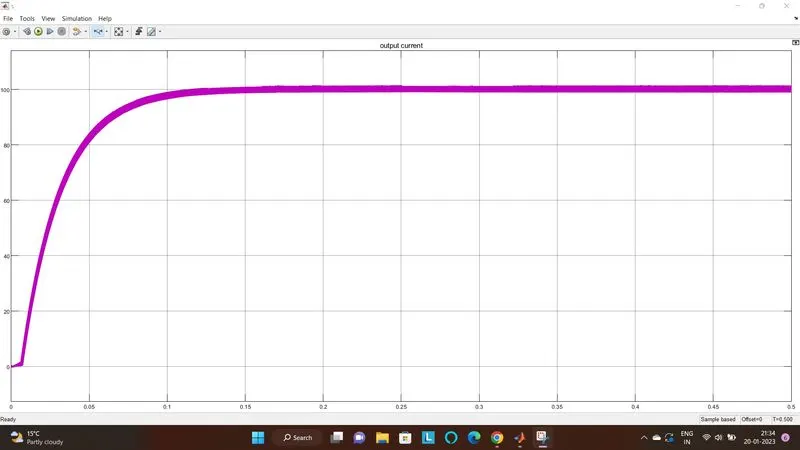
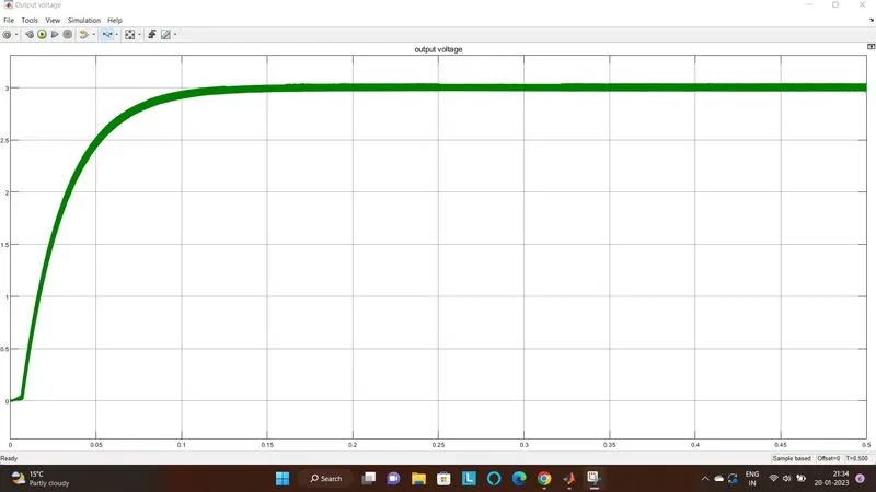
1) The main aim is to get efficiency as higher as possible and as you see in our requirement are getting approximately same.
so we can say that our efficiency is above / more than 90%.
1) As efficiency is calculated from output power/ input power so as we calculated for this converter as following:
Input voltage = 60V
Input current = 5A
Output Voltage = 3V
Output Current = 100A
from all the above data, we get the Input power is 300W and output Power is also 300W
so our efficiency is 100% without considering the ripple in voltage and current, if we consider the ripple also we can get the eifficiency more than 90%.