Project 2
AIM:
To Route the Wiring harness on Given car body and Prepare flatten view drawing in CATIA V5. Application of all Packaging rules, Industry best practices studied in this course shall be demonstrated in design. Apply Protection coverings as required.
INTRODUCTION:
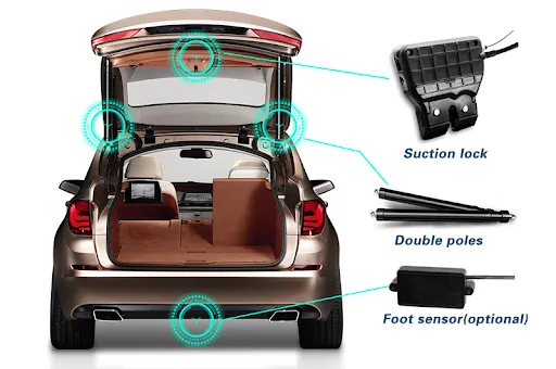
The trunk or boot of a car is the vehicle's main storage or cargo compartment it also have a hatch at the rear of the vehicle. It is also called a tailgate.These doors can be operated manually or electric powered. here we design the trunk or back door wire harness using the Catia.The Backdoor is an assembly of many parts such as inner panel, outer panel upper, outer panel lower and Reinforcement.Inner panel is attached to the outer panel using mastic sealant.
The wiring harness packaging rules and the industry best practices that have to be followed to complete this project are as follows
- Easy manufacturing, installation, removal, and maintenance must be considered while designing the wiring harness.
- Routing through small structural holes or openings shall be avoided to minimize chaffing and handling during installation.
- Avoid harness routing and clipping in the blind zone or hard-to-reach areas during harness assembly or service.
- Provide additional slack if needed according to the surrounding and harness bending requirement. For this project, a slack value between 1-5% is used.
- It should be made sure that there is no case of fouling while designing the wiring harness in the CAD environment. Additional clips/ clamps may be used to avoid fouling.
Back Door:
To download the backdoor in Backdoor CAD data
Construction of the Harness Assembly:
- Creating Context Assembly:
- A Context Assembly for Backdoor Wire Harness has been created, which will work as the main assembly as shown in the figure above.
- A Context Assembly will contain Backdoor Assembly data and Backdoor Wire Harness Geometrical Bundle Assembly.
- Positioning the Connectors & Clips to the Back Door Assembly:
Here, according to the requirement, we are using
- C-776438
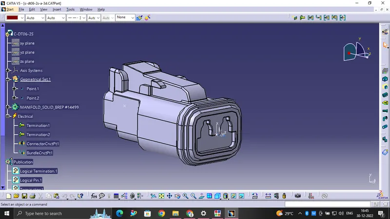
- C-DT06-2S
- C-1924487-2
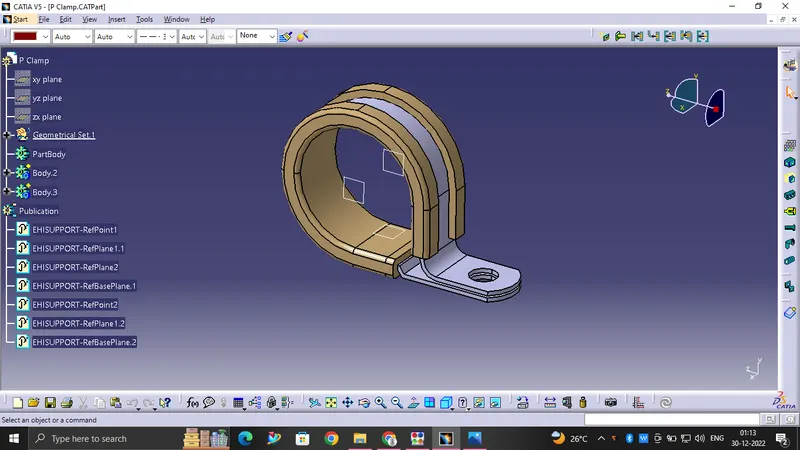
- P CLAMP
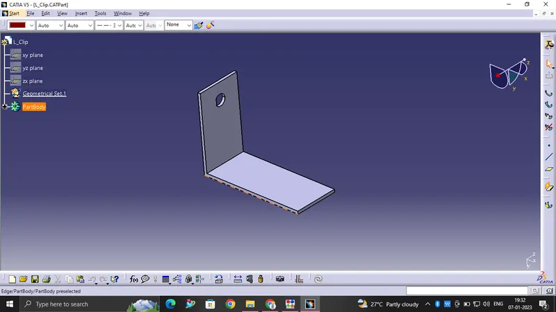
- L CLAMP
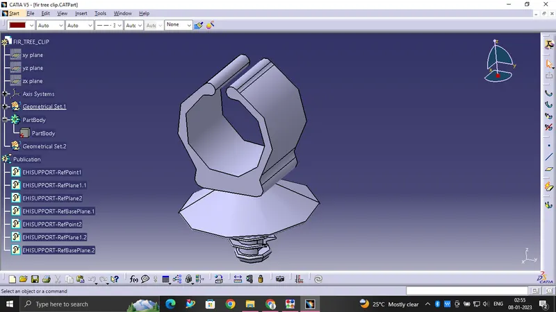
- FIR TREE CLIP
- C-DT06-2S
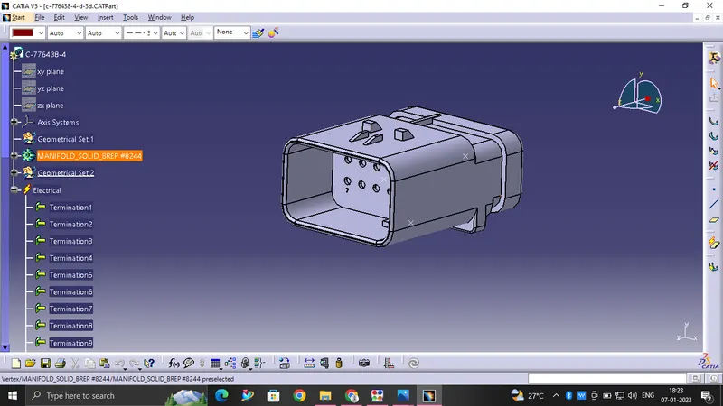
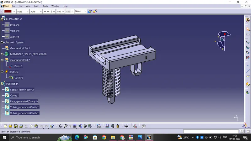
This CAD data was obtained from te.com. To electrically define a connector, we must first define the geometrical parameters such as the bundle connection point and connector connection point in the Electrical Part Design workbench for the downloaded connector.
The connectors are used for this challenge are
C-776438:
C-1924487-2:
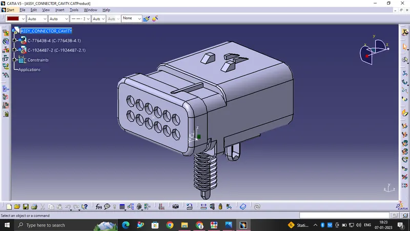
CAVITY AND CORE TO CREATE AN PRODUCT FILE:
P CLAMP:
L CLAMP:
FIR TREE CLIP:
C-DT06-2S:
PLACEMENT OF THE CLIPS AND CLAMP TO THE REQUIRED POSITIONS:
Placement of the connectors
I will provide ths connector because it is the main connector for all the wire and clips and clamps
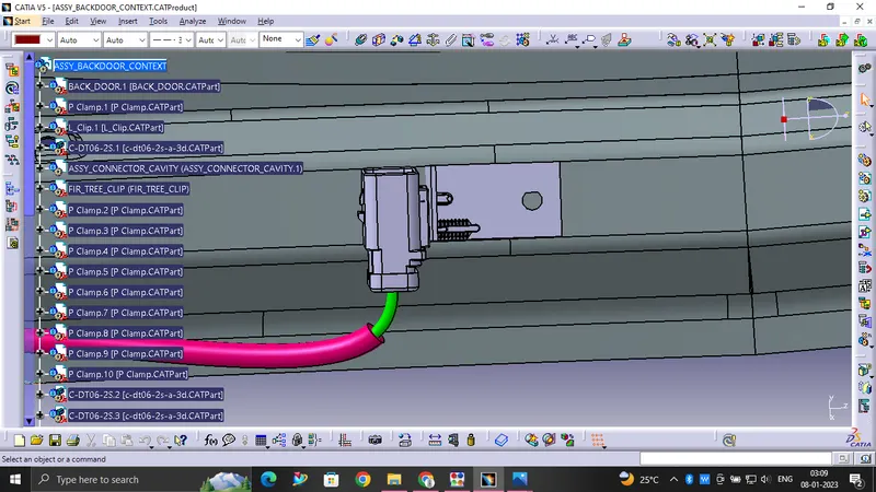
I will provide this connector for wiper motor connection
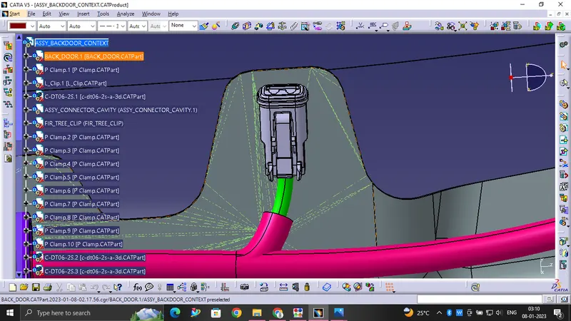
I will provide this two connectors for the Backlight,indicators and for brake light for left side
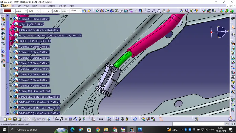
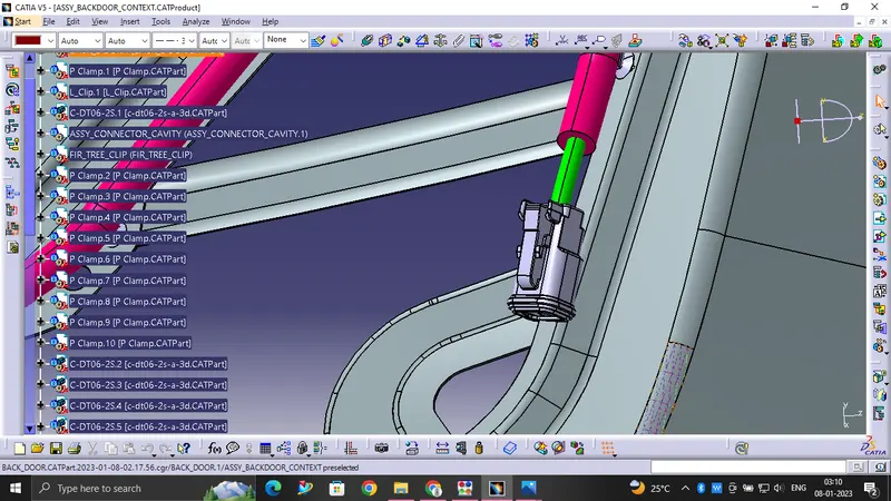
I will provide this two connections for Tailgate inner light and for the number plate
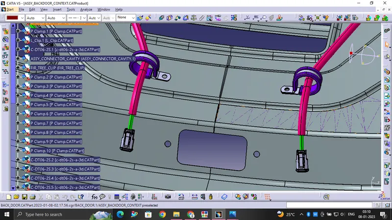
I will provide this two connectors for the Backlight,indicators and for brake light for rightside

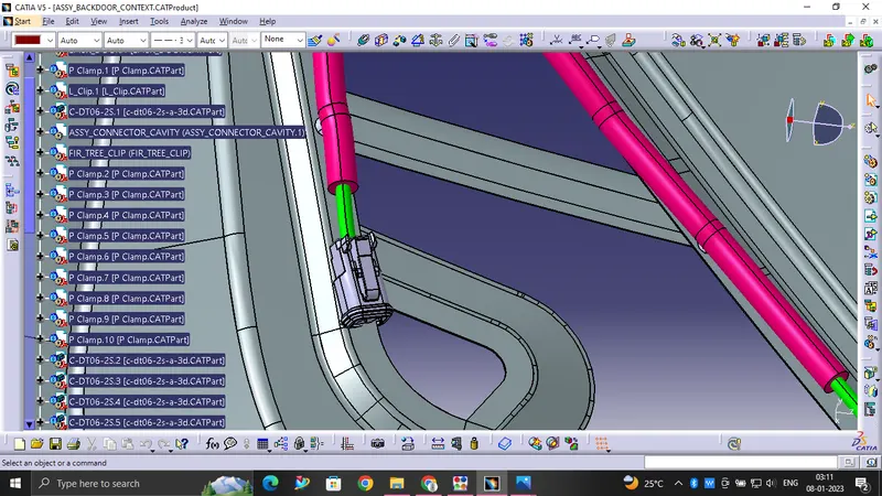
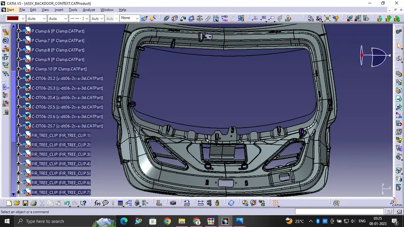
FINAL assembly of clips, clamps and connectors for the back door
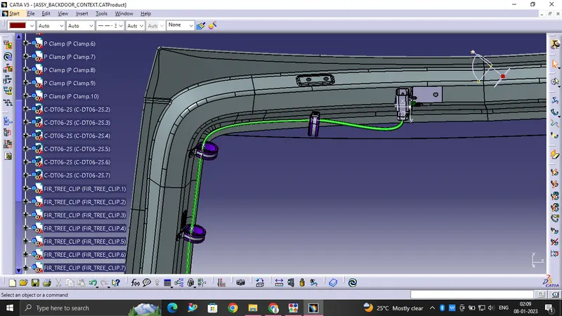
Bundle Routing:
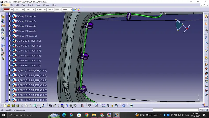
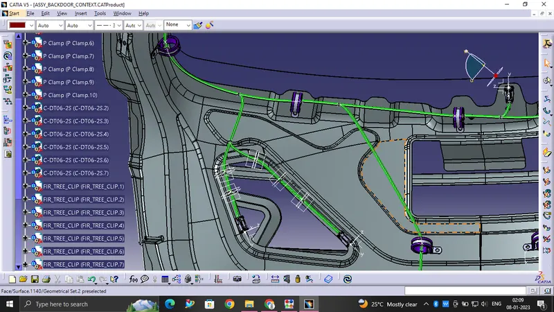
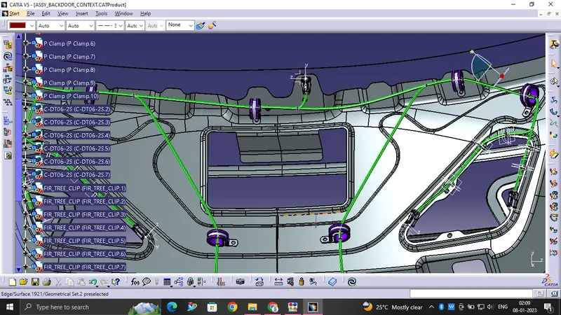
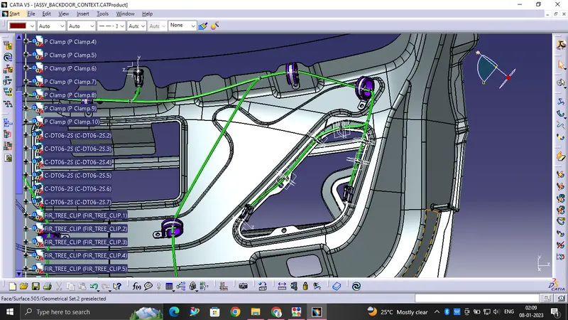
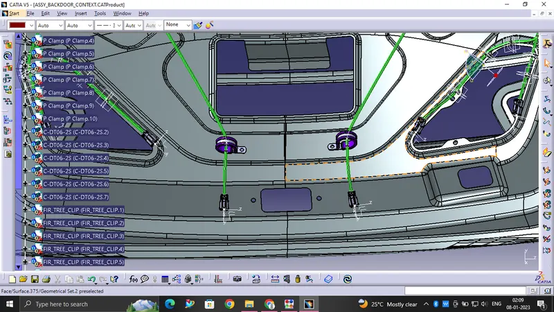
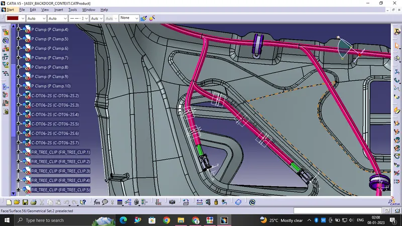
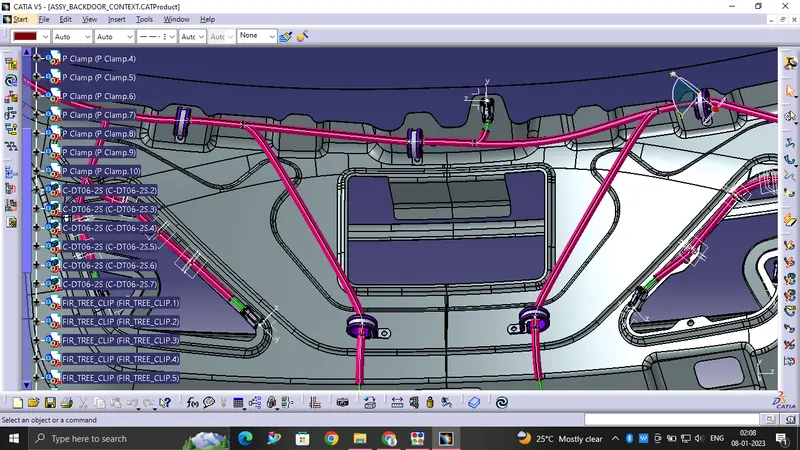
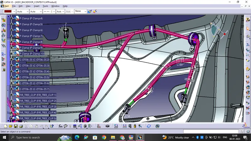
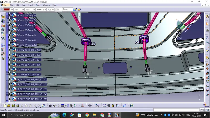
- The bundle segment is routed from the interconnection connector to the P clamp, fir tree clips and guided towards the 2 Pin connectors. while maintaining the Bend radius ratio of 1.4 mm
- We have used bundle thickness 5-10mm
Protective covering to the harness bundle:
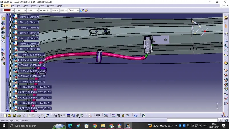
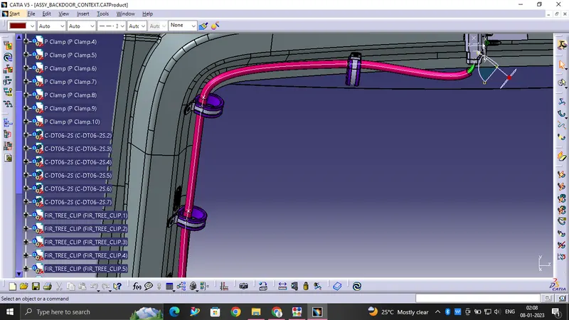
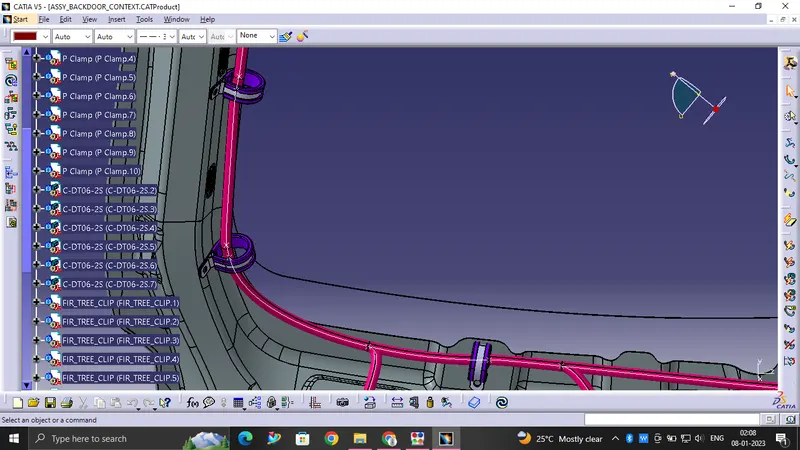
- After bundle routing, we have to add protective covering to the harness bundle so that it will get protected from the damage.
- Here, we have used PVC tape or insulated tape. for the current harness assembly.
- We have given start and end extremity wherever needed for the PVC tape or insulated tape.
Check the Bundle Connectivity:
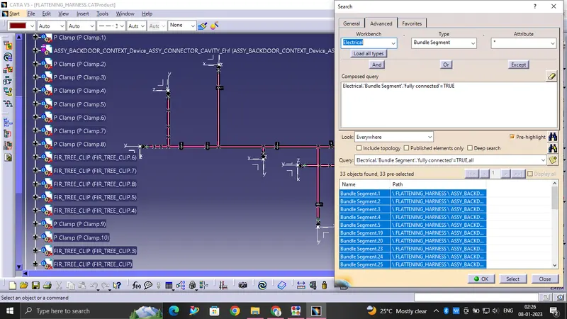
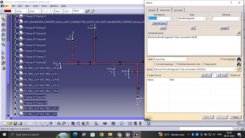
in this step, first we have to make sure that multi-branchable is selected then we have to go in Edit >Search > Advanced >Workbench - Electrical>Type - Bundle Segment>Attribute - Fully Connected
- By selecting 'True' option will show all the connected bundle segments while selecting 'False' option will show all the non-connected bundle segments.
- Here, we have selected for the 'True' option and searched for results. All the bundle segments are highlighted found showing that all the bundle segments are electrically connected
Creating flatten view of the Backdoor Wire harness geometrical bundle assembly:
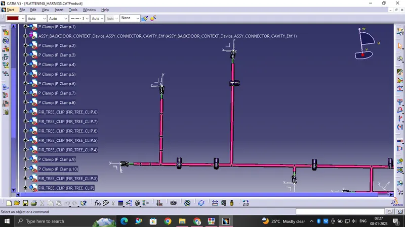
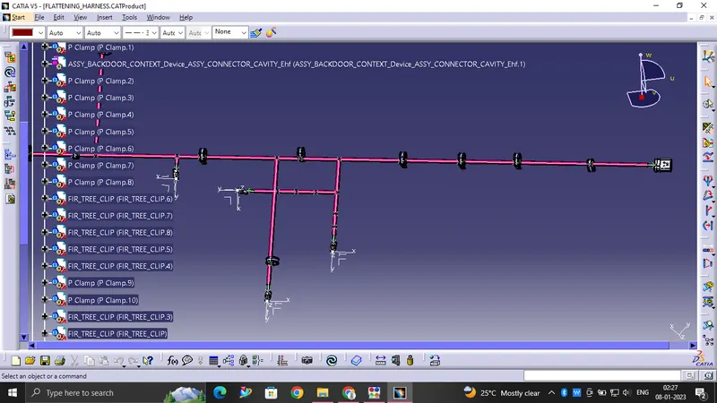
In this step, we will use Catia V5's Electrical Harness Flattening workbench to create a flattened view. We should also ensure that the flattening file is saved in the same folder as the other harness assembly files.
- The bundle assembly was extracted into a Back door wire Harness Flattening Product file, which was then flattened along the face of the interconnection connector.
- We developed a wires to represented in flattened view.
- we must rotate bundle segments connecting to the connectors using the 'Rotate' feature of the flattening workbench.
- It should be noted that the 'face' of the interconnection connector serves as the flattening plane, so we must rotate the bundle segments only along that plane.
- We used various features such as bend, rotate, and roll to streamline the harness for better representation.
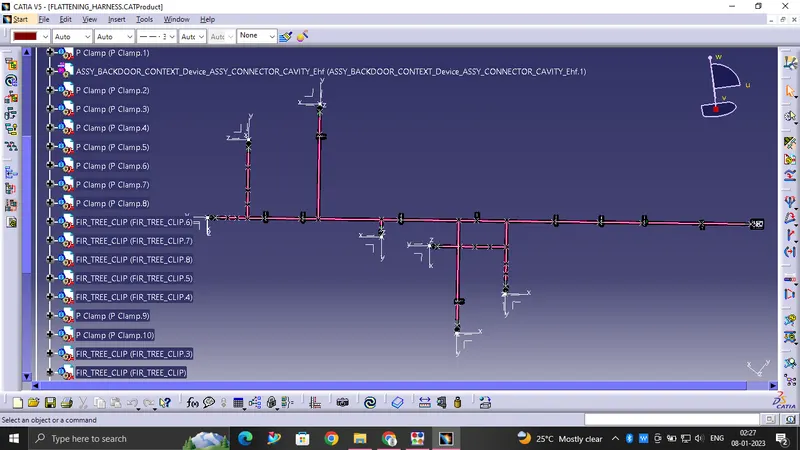
And convert this flattening wire file into igs FILE:
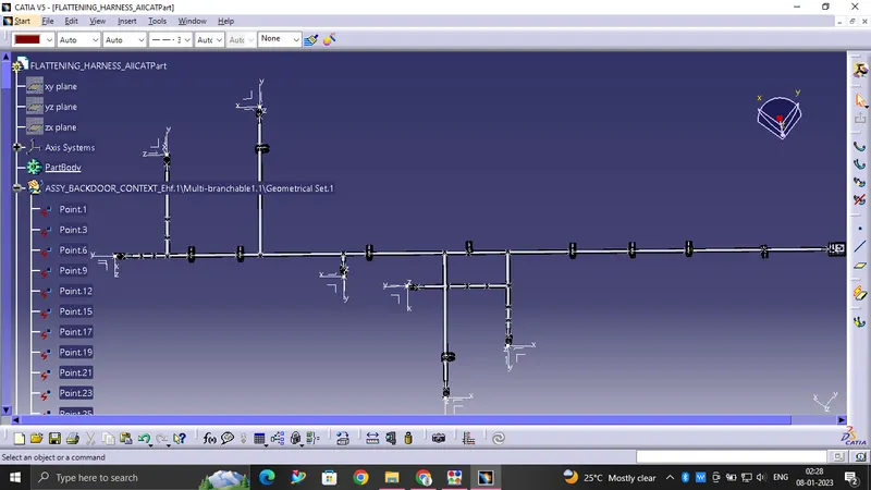
It looks like
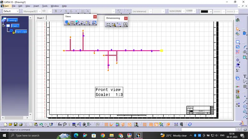
Creating the Drawing File For this Flattened Bundle segment:
To Creating new drawing file and defined all the necessary drawing parameters. We have to insert the front view of the Engine Harness Flattening Product file into the Drawing file.We have to define drawing properties as shown in above figure. It should be noted that in 'Dress up' settings 3D wireframe is always ON. If this setting is not selected then th bundle segments won't be visible on drawing view.
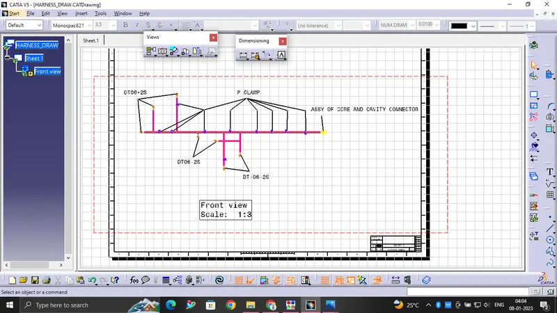
Conclusion:
To Routing of the wiring harness for the car Backdoor assembly has been succesfully done and prepared flatten-view drawing in Catia V5 as per the design requirements.