Project 2
Aim:
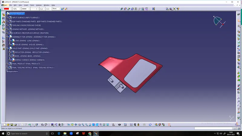
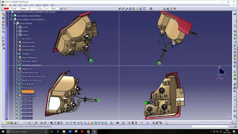
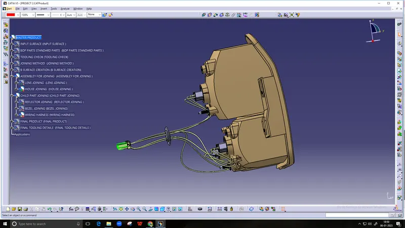
To create the a complete design of the tail lamp with all the assembly parts and child parts, also the attachment features by considering the design regulations in CATIA V5 Modelling Software.
Objective:
To the design the solid body tail lamp parts like lens and housing all other parts with the base thickness of 2.5mm.
To determine the reflectors shape and posotio0nong in the housing.
To use the standard parts of Bulbs, Screw boss and vent caps.
To obtain the red and clear lens separately in the tail lamp design.
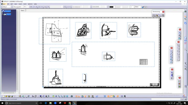
To obtain the final assembly drafting of the tail lamp design.
In the automotive the tail lamp is mounted in the rear part of the vehicle to let the other drivers know the approximate size and shape of the vehicle. It is the important safety factors for a vehicle. The color of the tail lamp is mostly red as it should be clearly visible to the other drivers. The lens and housing of the tail lamp are designed as per the industry standards by checking the all the regulations while designing the reflectors and making sure that there is no bleeding of light happening in the casing of the tail lamp design. Anti-fog condition is also been taken care of so that condensation does not occur inside the reflect region. The bulb which are used in the lighting industry are taken as inputs and placed at appropriate position in the reflection.
The General position of the tail lamp assembly in the vehicle as shown below,
Tail Lamp assembly and Positioning in the SUV Car
Methodology:
Creation of the Len’s solid body:
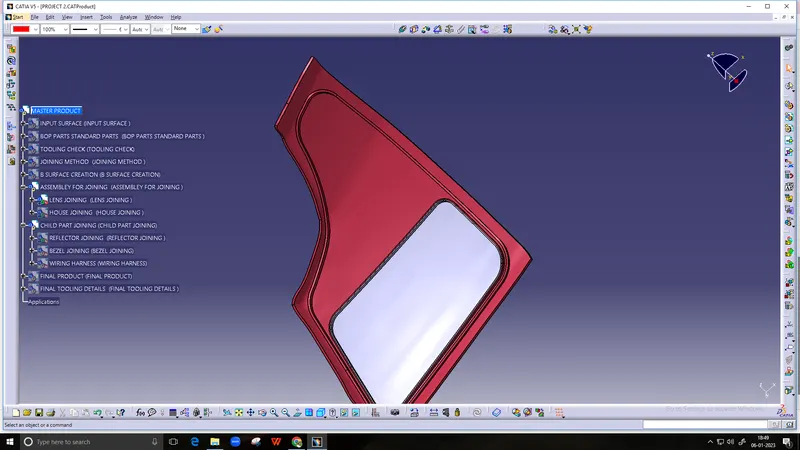
The class A surface of the provided lens are not properly structured well, some patch work is done to obtain the fine class B surface. Some rework is done to the class A surface at the edges. It is offset to 2.5mm respectively to make the class B surface. Both surface is joined by using the Class C surface to have closed volume of the lens solid body as shown below,
The closed surface volume is then converted into the solid body as shown,
The tooling direction is created for the lens to determine the draft angle of the lens body which is to check the lens will clear all the direction in the draft analysis.
The lens body appears as full green body which means the it clear all the direction, which can be easily remove from the mold, as shown below,
Creating the welding track to the lens:
Designing the welding track for the lens, by making the flange in the lens body and it is attached with it by making union trimmed with lens body as shown below,
Creating the Reflectors for the lens:
The tail lamp as three reflector function namely,
Tail stop Function
Turn Function
Reverse Function
The tail stop function will glow as red in colour when the vehicle stop or pause at motion of the vehicle, turn function will activated when the driver presses the induction direction and the reverse function will be activated when the vehicle will be moved in reversing the vehicle.
In order to design the reflector a parabola is first designed for the back side and the circular surface was made by taking the focal point as the center, both of them were split together to get desired shape and position of the reflector. Parameter and relations features was used to specify the diameter of the parabola so that in the future was used to modify the asper the requirement of the company.
Once the reflector is ready, now we place the bulbs to the midpoint of the reflector using the focal point meets in the reflector. The bulbs are standard parts in the industry so it is imported into the work place and then it is positioned using the focal point using the axis translation. Each functions the bulb color differs as mentioned below,
Tail\Stop Function – W21/5W Bulb
Turn Function – W21W Bulb
Reverse Function – W16W BULB
Along the bulb the holder and seating area of the bulbs also imported in o the workspace as it is also the standard parts it is attached with the reflector by union trimming at the focal point position of the bulb and reflector by positioning using the axis transformation. As per industry certain rules are followed which specifies what should be the minimum and maximum distance which each function should be placed by considering all these function the reflectors were be placed. By considering the industry aspects the positioning as done by following the industry standards.
Creating the lens housing:
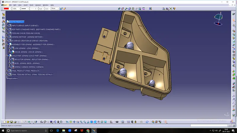
In order to create the housing for the lens we have to create the master section for the reference purpose. Master section is created using the help of surroundings, welding track of housing the lens body. The lens welding housing is done by using the HOT PLATE welding technique was to attach the housing and the lens body to accommodate this both lens and lens housing held at same meeting point.
To create the housing many industry factors are taken into consideration to make sure that there is no light bleeding happening inside the lens.
Creating vents caps and hole:
One of the primary thing we have to consider while designing the lens is to avoid the condensation. Condensation occurs to the bulb due to when there is temperature difference between the surrounding then the lens will become unclear from inside due to drop lets will formed. To prevent from this situation vent areas are developed in the reflectors so the heat generated can be easily comb out from the back side of the reflector and the temperature does not become high at those regions
The positioning of vents are also taken into consideration, which depends on these factors
It should not be visible to the customer.
It should be easy for them to perform their function.
It should not obstruct the flow of light or the light reflection.
Creating of Wiring Harness:
A cable harness, also known as a wire harness, wiring harness, cable assembly, wiring assembly or wiring loom, is an assembly of electrical cables or wires which transmit signals or electrical power. The cables are bound together by a durable material such as rubber, vinyl, electrical tape, conduit, a weave of extruded string, or a combination thereof.
Every vehicle provides the one wire each for 1 Tai; Function, 1ground Function, 1 turn Function, 1 stop Function, 1 Turn Function, 1 Reverse Function. In our project we are going to provide with 4 pole connector which provides all these wires coming out with it.
Color of wire for each function:
Tail stop Function – 1 Brown wire for Tail Function \ 1 red wire for Sop Function.
Turn Function – 1 Orange wire for Turn Function, 1 Black wire for Ground
Reverse Function – 1 White for Reverse Function and 1 Black wire for Ground
A grommet is designed at the back side of the housing which functions as a connector between the pole connector and the wires coming out from the housing. At the grommet addition wire can also fixed to give more function to the lamp.
Creating of final lens (Red and Clear lens):
In order to incorporate all three function n he tail lamp design, a clear lamp is also designed along with red lens. It is done by using the insert molding technique will be used so all the function ca be clearly visible and perform their functions accurately.
Drafting of Assembly and Child parts of Tail Lamp:
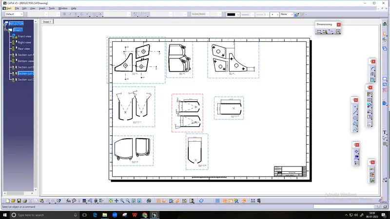
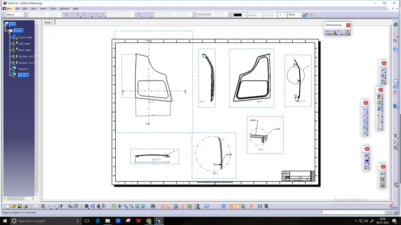
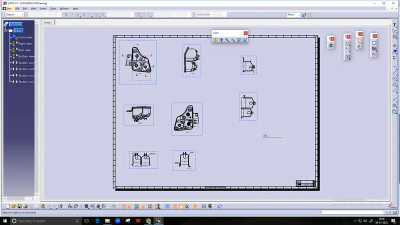
Dimensions and regulations for each part is shown detail manner using drafting as shown below,
Here initially we are going to see the assembly drawing of the tail lam design,
Bill of Material:
A bill of material or product structure is a list of the raw material, sub-assemblies, intermediate assembly, sub components, parts and its quantity of each needed to manufacture end product
The below table represents the BOM of the Assembly drawing of Tail Lamp Design.
The below table represents the BOM of the Child Part drawing of Tail Lamp Design.
Conclusion:
The complete tail lamp design of lens and housing assembly by successfully made by following the industry standards.
The solid lens and housing was made which can be attached together with Hot Plate welding.
Attachment features like mounting and screw bosses were designed at the rear side of the housing to attach the housing the reflector to the housing.
Draft analysis was performed on each stage to cross check if the parts made can be easily machined by using the required draft applied to each component.
Drafting of the lens and housing assembly was achieved to represent the specification of each part.
Bill of material was also presented to know all the information of the tail lamp design.