Project 2
AIM & INTRODUCTION:
As we are all aware ,The AEC industry is moving towards Artificial Intelligence and Machine Learning to enhance their project process and workflow. The industry is pulling out from the traditional tools to adapt and leverage the new technology and techniques for a better tomorrow. In this context, computational tools like Dynamo has banged into the industry to improve the project design process and efficiency.
Dynamo is a Visual Programming tool that uses visual expressions, spatially arranged graphics and texts, as its syntax or secondary notations. In spite of creating programs textually, this programming language allows the users to manipulate the graphical elements called ‘nodes’ in an interactive manner. Here, each node symbolizes a specific function of the API (Application Programming Interface) and have an input and output port. A node’s output port is connected to the other node’s input port via a wire to transmit data or information.The flow of information is only in a single direction through the wires.
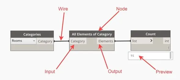
Dynamo is an Open Source Programming Tool that gives it an edge above other visual programming languages (VPL). An open source user community often introduces new concepts and ideas that support the gradual improvement of the tool and extend help through the forum.
When integrated with Autodesk Revit, Dynamo solves modeling challenges in a smart and fast way. The library of nodes of the VPL gives access to the users, to select a specific node to perform a task, instead of coding. Dynamo gives direct access to the Revit API, where programming skills are not required. The mathematical tools of the dynamo, help in the easy evaluation of the building parameters. A project model can be easily developed, accessed, and edited with dynamo.
Dynamo in Revit gets linked to the file and the page or view through which it is launched. When any changes are made to a Revit file in dynamo, they get updated to the page from which dynamo was launched.
Project Information:
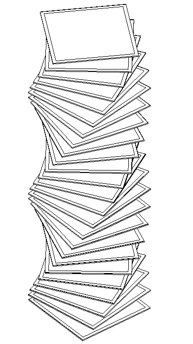
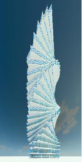
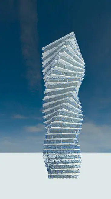
Here we will create a 25 storied complex twisting commercial tower model using Dynamo script. After importing to Revit we will add facade design for an asthetic view using massing. Each floor acquires 600 sqm in the tower with curtain walls including a 1.5 m cantilever surrounding the curtain wall to add facade for a walkway. It is basically designed for commercial purpose with expansive area. Let's start with Dynamo Script followed by the procedure below.
Procedure For creating a multi storeyed Twisting Tower using Dynamo Script
- Opened Revit Home page > New Model > Architechtural Template > Ok
- As File opened > Set the unit to meter >Go to manage Tab > Visual Programming Panel > Dynamo
- As Dynamo Home Page Opened clicked on New > Dynamo working window opened.
Creating a Rectangle
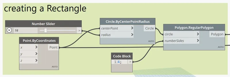
- At left side in Library searched Circle.By center point radius node & added > A Number Slider node added for Radius input & connected through wire > For center point Input point. by coordinate node connected to center point > Polygon.Regular Polygon node created > For number sides a Code Block added > input added as "4 "> Number Slider value fixed to "16 " > all the created nodes are connected through wire to respective input to get the result without any warning at the time of Running as we can see in below attached image.
- All the nodes selected by Cross selection > Right click > Created Group and renamed the group by double clicking on it as Creating polygon > Changed the colour from that dialogue box.
- At Bottom Left corner of Dynamo window For Run Option manual slected.
Creating a Floor Outline
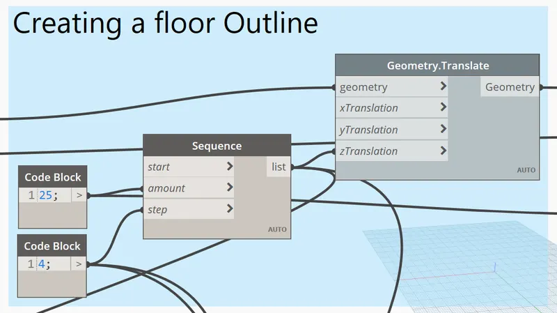
- Now to create floor Geometry.Translate node added > Polygon output is connected to input Geometry > As we need floors so we need to add Z-Translation input > For that a Sequence node added > Two Code Block node added for Amount & Step input > Output of sequence (List) added to the Z-Translation input > Clicked on Run at the bottom left corner for manual Run and we can see the geometry in dynamo window.
- Selected the ungroup nodes by cross selection and grouped it as Creating a Floor outline And the group fill colour modified.
Creating Levels
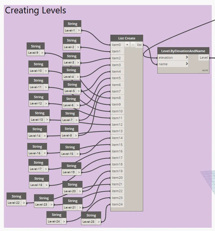
- Now to create Levels List Create node added > Clicked on "+" to add items as levels for 25 floors [Item0 to Item24] > To add level name 25 times String node added and Named as Level-1 , Level-2,Level-3,level-4,level-5,Level-6,Level-7,Level-8,level-9,level-10,Level-11,level-12,level-13,Level-14,Level-15,level-16, Level-17, Level-18, Level-19 , Level-20, Level-21, Level-22, Level-23, Level-24, Level-25 respectively in each string as we can see in below attached image.
- All strings connected to List item through wire.
- Level.ByElevationAndName node created > Level connected to the Sequence output List > List Create Output List is conncted to the input Name.
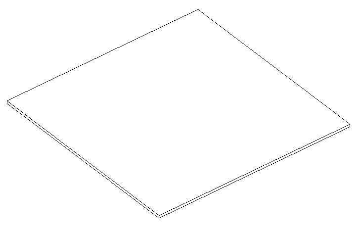
- Switching to Revit we can see the levels with 25 Floors.
- Selected all the ungroup nodes > Right click > Create a group & Renamed as Creating Levels > Fill colour modified.
Floor Rotation
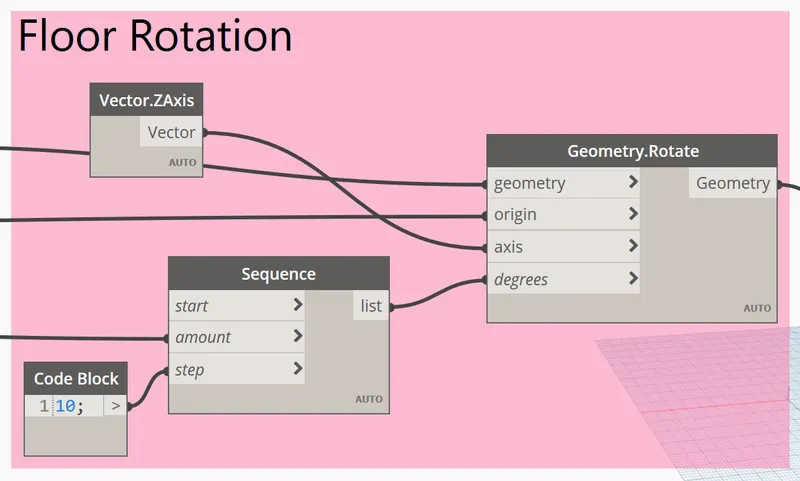
- As our aim to create a twisting Tower so we need to Rotate the Floor to get a Twisting tower look with a sequence.
- Geometry.Rotate node created > For the Input Geometry, Geometry.translate output Geometry connected through wire > For Origin input the Point. bycoordinate output connected through wire.
- For axis of rotation Vector.ZAxis node created > The vector connected to input axis through wire.
- For degrees a Sequence node added > Amount input connected to Code block in Cretaing floor Group with value 25 .
- For step input another Code Block node added > Value added as "10" for degree rotation
- Selected all the ungroup nodes by cross selection > Right Click > Grouped it and named as Floor Rotation > Group Fill colour modified.
- Polycurve.Curves node created > Geometry.Rotate Output Geometry connected to curve input
- In dynamo window we can see the rotated Floor geometry.
Creating Concrete floor
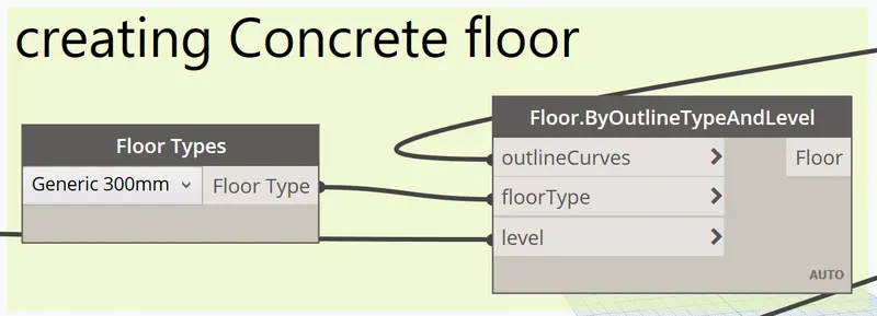
- Floor.ByOutlineTypeAndLevel node created > First input outline curves is connected to output of Polycurve.Curves > For Floor Type a Floor Types node created > In Floor types, " Generic 300mm" from the dropdown selected > The output of Floor Type is connected to input floor type of Floor.ByOutlineTypeAndLevel > Input Level is connected to Output Level of Level .ByeElevationandName node > All the remaining ungroup nodes selected > Right click > Create group and renamed as Creating Concrete Floor > selected Run and all the concrete floors updated in drawing area.
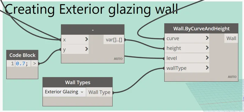
Creating Exterior Glazing wall
- Wall.ByCurveAndHeight node created > Input curve is connected to output of Polycurve.Curves > For Wall Type input another Wall Type node created > From wall type drop down Exterior Glazing Wall selected > Input Level is connected to output Level of Level.ByeElevationandName node > For Height Input a substraction (-) node created > Input X of (-) node connected to Step Input value (Code block having value 4m)> Another Code Block Created and the value has taken as 0.3 which connected to the Y input of "-" node .
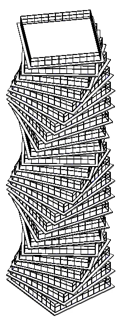
- The Output of - node connected to height input of Wall.ByCurveAndHeight > Run the script and we can see the glazing wall in revit window.
- All the remaining ungroup nodes selected > Right click > Create group and renamed as Creating Exterior Glazing wall and changed the colour.
Creating Levels For Roof
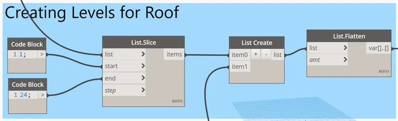
- List.Slice node Created > List input is connected to the Level.ByElevationAndName Output > For start and End input two code block node created and value added as 1 & 24 respectively & connected by wire.
- List Create node created > Item0 input is connected to List.Slice Output > Clicked on "+" to get Item1.
- we need item1 as we need to create a roof for 25th floor as Level-26 > Run the script and we can see the Levels in revit window.
- By cross selection select all the ungroup nodes > Right click > Create group and renamed as Levels For Roof > Changed the filled color.
Creating Level-26
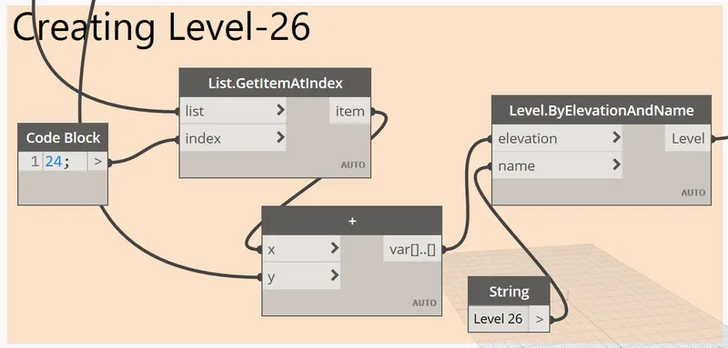
- List.GetItemAtIndex node Created > List Input is connected to sequence output of Floor Outline Group > For Index input a code block created with an assigned value as 24, since for 25th floor the index number is 24 > Through connecting wire code block is connected to Index input.
- Addition (+) node created > X input parameter is connected to the output of List.GetItemAtIndex > Y input parameter connected to the code block assigned the value as 4 (floor height) in Floor Outline Group.
- Level.ByElevationAndName node created > Addition(+) node output is connected to the elevation input parameter of Level.ByElevationAndName > For Name input a String node created with value assigned as Level 26 and connectd through wire > Run the script and we can see Level-26 in revit window.
- By Cross selection all the ungrouped nodes selected and grouped as Level-26 and modified the color.
- The output Level of Level.ByElevationAndName connected to Item1 input of List create node in Levels For Roof Group.
Creating Roof
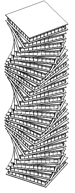
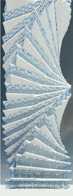
- As each floor is rotated in a sequence of 15 deg with respect to below floor, So there is opening in roof of each floor as its not totally covered by floor.
- To cover these openings we need to add roof to each floor.
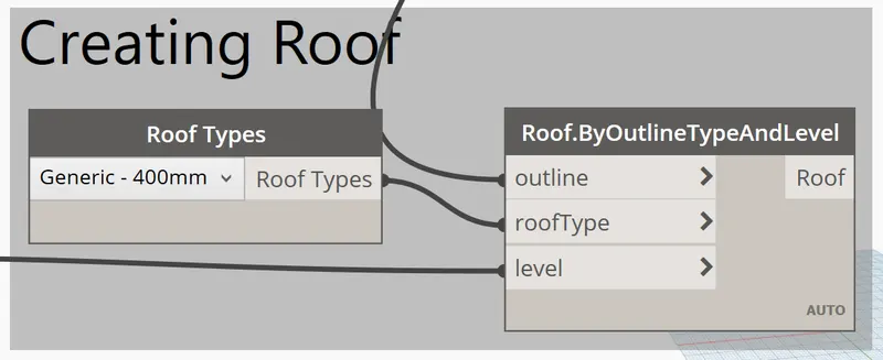
- so we need to create Roof.ByOutlineTypeAndLevel node > The outline input is connected to Polycurve.Curves output > For Roof Type another node created as Roof Types > From drop down Generic- 400mm selected and connected through wire to respective input > The Level input is connected to the List.Flatten node output in Levels For Roof Group > Run the script and we can see the Roof in revit window.
- By cross selection selected the ungrouped node what we created > Right click > Create group > Renamed as Creating Roof.
2. Procedure For Adding Facade design to the Tower using Massing
- Let's First create a pattern which we are going to use in massing.
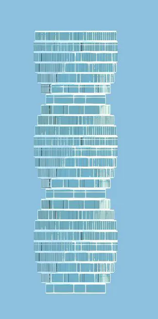
- Revit Window > Cliclked on 1st Level > As Level-1 plan opened go to Massing & Site tab > Conceptual mass Panel > selected Show Mass Form and Floors from drop down.Clicked on In-Place Mass > Named as Mass-1 > Go to Draw Panel > Make sure model line active > Picked line tool > Drew line surrounding the Floor > 3D View > Go to Form > Create Form > extruded & adjusted within the clear height.
- Selected the surface > Divide Panel > Divide Surface > once the vision appered its rectangle by deafault > changed pattern in property browser > selected hexagonal from dropdown > As it was not a perfect hexagon > so we will create a perfect hexagonal panel which can use as a faccade design.
Creating a perfect hexagonal Frame
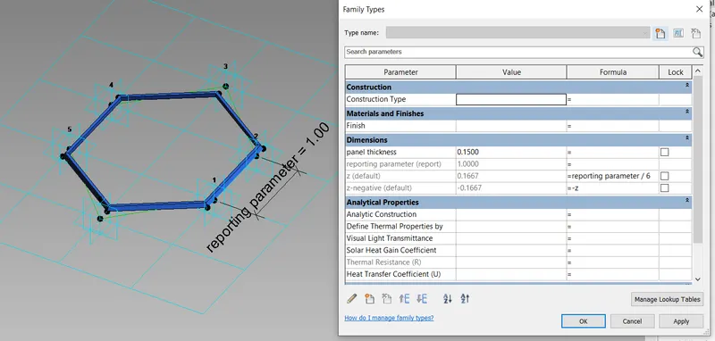
- File > New > Family > Selected Template File > English > Metric Curtain panel based pattern > Open.
- Default Rectangle Pattern opened > changed to hexagon from dropdown > Changed Horizontal spacing & Vertical Spacing to 1m.
- Work Plane Panel > Set > Selected vertical plane > Draw panel > Selected point tool >Make sure draw on work plane is active > Placed a point little bit out of existing point > Similarly did for other point in vertical plane to create a perfect Hexagon.
- As our offset was not matching , for that -ve offset distance we need to create a associate parameter > Named as Z negative Parameter > checked in Instance Parameter.
- To mantain same -ve offset value for all associate the z negative parameter to all -ve value.
- Go to Family type tool > Dimension data > value changed to 0.2m in z negative > apply > ok > The value applied to the pattern for all -ve offset value.
- Similarly create Z instance parameter > Associated to other +ve offset value > Go to family type > Set Z negative formula to - Z > apply >Ok
- Select set work plane > Select horizontal plane > dimesion panel > Aligned dimension > 1m \
- Go to Label dimension panel > Label > Create Parameter > checked in Instance > checked in Reporting parameter > add name as Reporting parameter > ok
- Go to family type > Formula of Z set as Reporting parameter /6 as it is a hexagon.
- Selected two points what we had drawn > Clicked on Spline through through two points tool > Checked in "Is reference line" in properrty browser > Similarly drew for all the points & make sure checked in Is reference line.
- Before creating new work plane select the old deafult hexagonal plane > pressed HH command to hide work plane> picked point tool from Draw panel > Make sure to active draw on face > Placed the point on one of these new reference plane.
- Work Plane Panel > Set > select the point reference plane > Picked rectangle tool from Draw panel > Make sure Draw on work plane selected > drew the rectangle and adjusted the rectange size and tappered it little bit for a asthetic look.
- Select the rectangle > hold the control key and select the reference plane > Clickled on Create Form in Form Panel.
- By tab key selected the form > Go to property browser to change the material > As i wanted a blue colour so selected Aluminium Anodized blue > Apply >Ok
- Now go to realistic view to see the colour> Family Editor panel > Load into Project and close >Clicked on yes in save warning.
Contituation Of Facade by massing
- As already Level-1 massing is open select the pattern what we created now > once the patttern visible its still not perfect so select pattern in surface > we need to change the U grid & V grid fixed distance in property browser.
- Here we had option to create an associate parameter for fixed distance > Go to V grid fixed distance > create parameter named as X > Checked in Instance parameter > Ok > Apply.
- Similarly go to U grid distance > Created another parameter as Y > checked in Instance parameter > Ok > Apply.
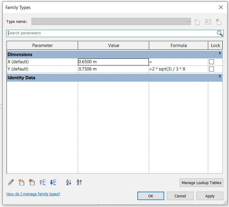
- Go to family Types > Set Formula for Y =2 * sqrt(3) / 3 * X > Apply >Ok
- Now Set the value of X to 0.65 to get a perfect hexagonal look.
- Go to In-Place Editor > Finish Mass
- Selected the massing in level-01 > Copy to clipboard > Paste assigned to selected level as level-02 > Clicked on Level-02 plan > selected the massing > Modify panel > Rotate the massing to proper position.So we can recheck in 3d view.
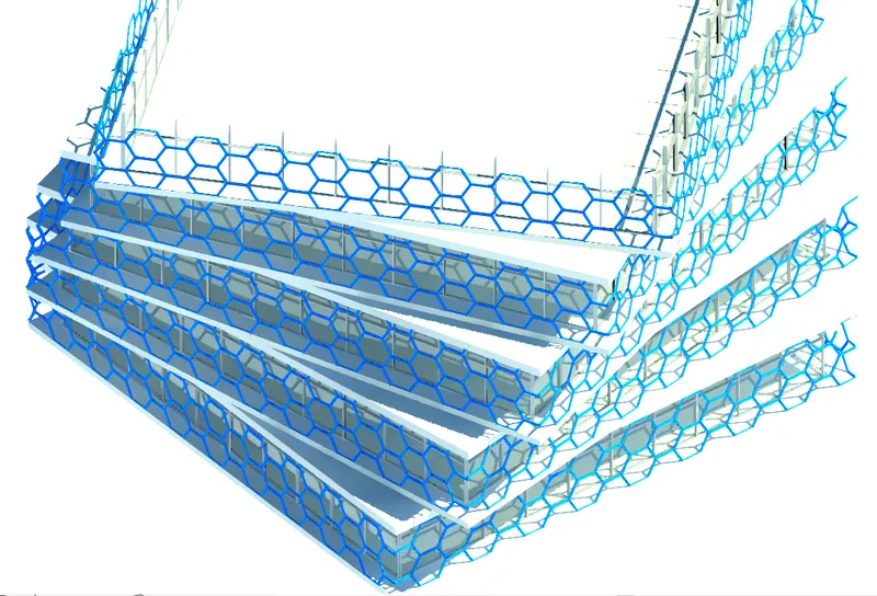
- Similarly Faccade created for the othe floors by using same procedure.
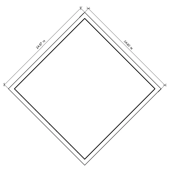
PLAN VIEW
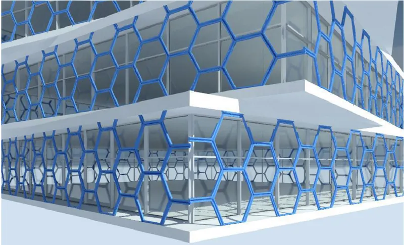
CLOSED FACCADE VIEW
3. CREATING WALKTHROUGH VIDEO & PRINTING OF 3D RENDER VIEW
- Clicked on Level-01 Floor plan > View Tab > Create Panel > 3D view> From drop down pick walk through > Placed the camera > Drew path > Set the frame to 200 > adjusted the frame by changing camera position > Played to check the view from all orientation.
- To export walkthrough > Go to file > Export> Images and Animation> Walk through > selected the save file location > selected frames range > OK
- Selected a Frame view > View tab > Presentation Panel > Render > Saved to project
4. PREPARING REPORT ON PROS AND CONS OF BIM IN PROJECT
BIM, is an effective technique for conceiving, planning, and designing structures of any size and complexity. To decide whether a BIM system is right for us and how BIM and general construction go together, we have to keep in mind the following pros and cons of BIM modeling.
Advantages of BIM
- Better planning and design: Using BIM, you can visualize a completed building and all its components and systems before the first shovelful of dirt is moved on the construction site. This information allows better planning and design that takes best advantage of available space and resources.
- Fewer reworks: BIM allows you to see potential problem areas and fix them before the error is committed in the physical world. This reduces the need for costly rework and revision.
- Savings on materials: BIM systems track and monitor resources and provide detailed information on needs even before construction begins. You are less likely to order more than needed and can replenish supplies only when necessary.
- Support for prefabrication: BIM allows you and your partners to more easily prefabricate components of the project offsite, which saves time and money.
- Subsystem insights: One of the premier advantages of using BIM is the ability to see each subsystem within a building and understand its context. How does that system exist in relation to others, and what’s its role in broader building function? With this information in-hand, facilities managers can make better decisions about how they manager, alter, and maintain different subsystems, and the effects of those decisions on the building.
- Dynamic updates: Especially during building and renovation phases, dynamic updates empower real-time insights about a building. If you change X variable in a BIM plan, it updates Y and Z affected systems, to show a true-to-form model of what those changes look like and what they mean for facilities as whole. This intuitive action-reaction relationship cuts down on the guesswork of modifying facilitie
- Clash detection: What happens when you make a change to one subsystem that disrupts a different subsystem? Trying to route plumbing through HVAC ducting, for example. These types of clashes derail development and can cause bigger issues for facilities managers and contractors when they become apparent. Clash detection through BIM prevents these issues from arising by stopping the actions that lead to them.
- Eventually, the professionals involved have the flexibility to use all of the information in the model to improve the design before it is produced by working together as a multidisciplinary team. There’s no denying that BIM’s influence is expanding, and the AEC industry is undergoing a good shift.
- MEP engineers utilize it to improve the routing of the plumbing system and HVAC ducts, as well as maximize spatial coordination between equipment.
- Efficient maintenance and improved lifecycle management
- BIM is a shared knowledge repository that gives a wealth of information on structures from the development phase until demolition (if and when this happens).
Disdvantages of BIM
- Incompatibility with partners: BIM is not yet universally used among Construction Professionals. There is always the possibility that one of your partners or subcontractors may not use BIM and may not be able to use your models.
- Legal issues: The legal ramifications of using BIM software have not yet been extensively tested, let alone settled.
- Cost of software: BIM software requires a substantial investment in new technology. The advantages usually make the investment worthwhile, but only if the software is used to its full capacity.
- Lack of experts: The relative newness of BIM means that there are limited numbers of experts working in the field. Your software purchase may require an additional investment in training and education.
- Training & Staff: An investment of time and resources in training will be required to embrace BIM. As whenever learning something new, it means the process may take longer to start off with as people undertake training and then essentially learn on the job. There needs to be a mindset and a commitment that this will get easier in the long term as change becomes ingrained in the daily operations of the business.
- End User Engagement: BIM isn’t just about the construction of a building, it can also benefit the management of the facilities after the handover stage. However the drawback is that contractors can often spend hours of resource time though inputting data such as product specifications and instruction manuals only to find that they are ignored by the onsite facilities team.