Project 1
AIM & INTRODUCTION
As we know BIM is information Modelling & information Management in a team environment. All team members work to the same standards. BIM creats value from the combined efforts of people, Process & technology.
An important aspects of BIM is the concept of parametric objects, these objects consist of geometric definitions & associated data & rules, have rules that determine when a particular change violates object feasibility regarding size,manufacturibility etc. Have the ability to link to or receive, export sets of attributes to other applications & Models.
There is a Level of Maturity comes into consideration which is the process of moving the AEC industry to full collaborative working in progress.The broad concept is to define the level of BIM from 0 to 3.
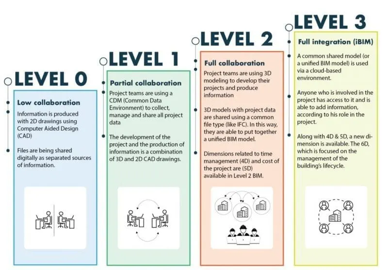
By considering the important aspect of BIM we will commence a model an Architechtural Residential apartment with respective structural model for the same. By using Revit we will model the project with step by step procedure.
Project Description
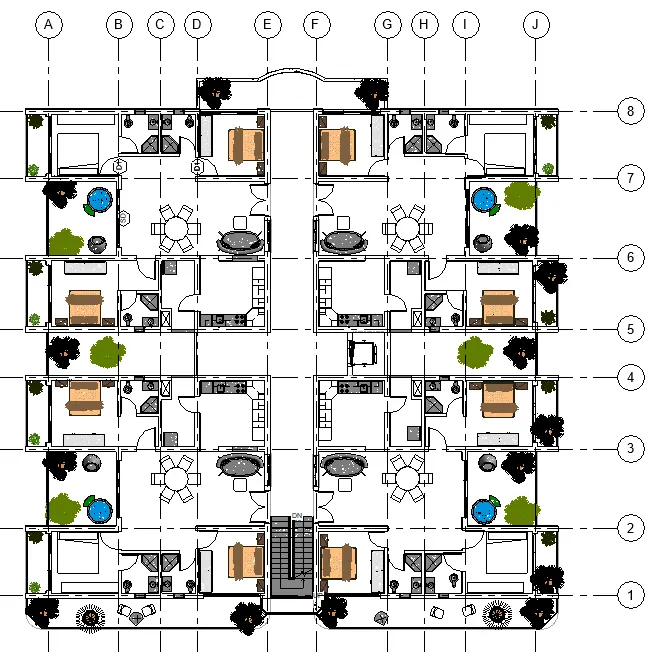
A multi-storey Residential apartment is of 7 storeys with stilt parking facility.Each floor has Four 3BHK units (3 Bed rooms [10 sqm, 13 sqm, 9 sqm], 1 Living cum Dining [ 30 sqm] , Kitchen [ 10 sqm] , Utility [5 sqm] , Three Toilet [3 sqm each] , Sitout [12 sqm]. All four units connected by corridor of area 54 sqm. For access to upper floors a staircase [ 6 sqm] & a Lift [3 sqm] provided. For exterior view 1.5m width cantilever projection is there in each floor. stilt floor height is 5 m & each typical floor has a height of 3m.
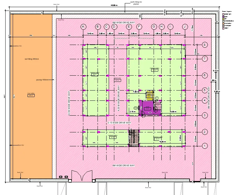
In Stilt Floor a drive way acquring area of 920 sqm & parking [378 sqm] is planned. A guard room is provided in Stilt which acquire 15 sqm. A play area is designed with 368 sqm area.
Total project area 1937 sqm is surrounded by a Boundary wall. Its route access is connected to a 10m wide road .
We will see the 3D visualization of all what we described above by using architechtural elements. In addition to that we wil model the structural elements with reinforcement. Further more BOQ and Layout will be printed trade wise.
All step by step procedures are explained below.
PROCEDURE FOR ARCHITECHTURAL MODEL
Opening An Architechtural Template & Creating Levels & Grids
- Revit home page > New Model > Architechtural Template
- Clicked on East Elevation in project browser > architechture tab > Datum panel > Level
- Positioned the cursor over the left endpoint of the 01-Lower level line,moved the cursor up 5000mm and clicked to begin a new Level.
- By following the procedures Levels created at each floor height distance and renamed as Ground Level , Stilt floor, 1st Floor, 2nd Floor, 3rd Floor, 4th Floor, 5th Floor, 6th Floor, 7th Floor, Terrace Floor & LMR/ Head Room Level in ascending order from ground to top.
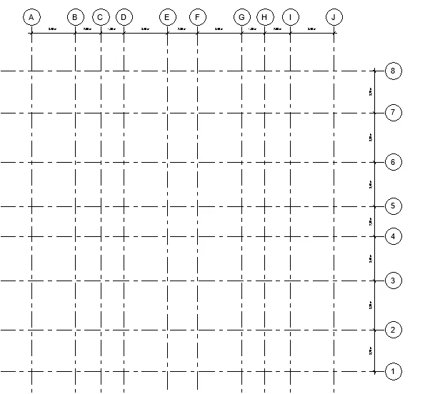
- To create grids clicked in first floor > Arcjitechture tab > Datum Panel > Grid >Clicked Modify | Place Grid tab Draw panel and selected a sketch option. Use (Pick Lines) to snap the grid to an existing line, such as a wall.
- Clicked when the grid is the correct length.
Creating a 1 unit plan 3BHK plan with Placement of Components
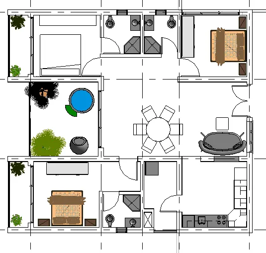
- Clicked in first floor in Project browser > to draw wall Architechtura tab > Build Panel > Wall drop down > Wall: Architechtural > selected the 200mm wall in property palatte > c/c of wall selected > Base constraint as 1st floor & Top constraint as 2nd Floor selected & Drew wall as per self designed plan dimension for one unit > by using modifying tools wall drawn
- After done placed door & window in wall > Architechture tab > Build Panel > door /window > selected the desire door/window in type selector and placed in wall plan.
- To place furniture components architechture tab > Build Panel > Place a component > selected the furnitures in type selecter which wanted to place > placed in plan by mantaining the position by cicking space > To insert some new components go to Inert Tab > Load Autodesk Family > In browser used browse tree to narrow the content display > Furniture Category selected > Further narrowed by selecting Beds/ Seating > Clicked to select multiple items > Load to project.
- similarly plumbing components & kitchen components placed in floor plan.
Creating the 4 units 3 bhk plan with Lift & staircase
- Mirrored the plan of 1 unit (3 BHK) by mantaining a corridor of 2.1m in between two units by using mirror by draw axis from modifying tool. In this procedure 4 units created.
- Lift wall drawn and staircase area also mantained in plan as we can see in attached image.
- To create a floor clicked architechtural tab > Build panel > Floor Drop down > Floor: architechtural > selected the floor type in type selecter as 150mm
- Drew the floor broundries, using the sketch boundary method > Finish Edit mode
- Selected yes in wall attach to floor bottom dialogue box option.
- To create railing in attaching to host > architechture tab > Circulation Panel > Railing > drop down > sketch path > Finish > modify the railing prperty to glass panel without balustrade.
Creating Stilt Floor
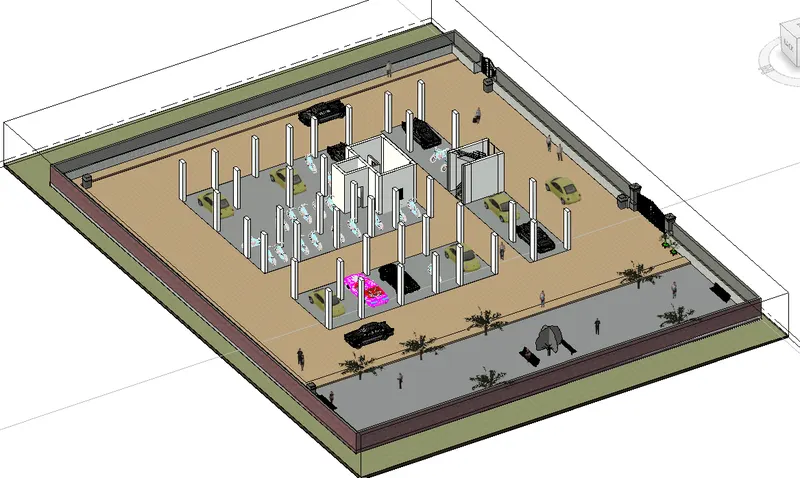
- Clicked in stilt floor in Project browser > to draw wall Architechtura tab > Build Panel > Wall drop down > Wall: Architechtural > selected the Boundary wall in property palatte > c/c of wall selected > Base constraint as stiilt floor with base offset as -0.3m & Top constraint unconnected with 2.0m & Drew wall as per self designed plan dimension.
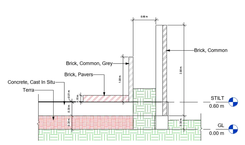
- 100mm Non structural wall created with a height 1.0m at a distance 0.5m from the boundary wall. It filled with 300mm depth loamy soil.
- 300mm stilt floor created & for side walk 1m width paved way made adjacent to the 100mm wall.
- Main gate component is added in stilt level > Place component > selected the family in Type selector > Placed in between the walls as we can see in attached image
- park area width 9.6m layered with 300mm terra soil & 150mm depth plant soil for grass lawn.
- Tile Finishing added in Floor property for the parking ,drive way & Park area.
- Vehicles ,Plants & entcourage family loaded into project and placed in stilt level for the realistic view which we can see in 3d view.
Replicate the Typical floors to Upper level
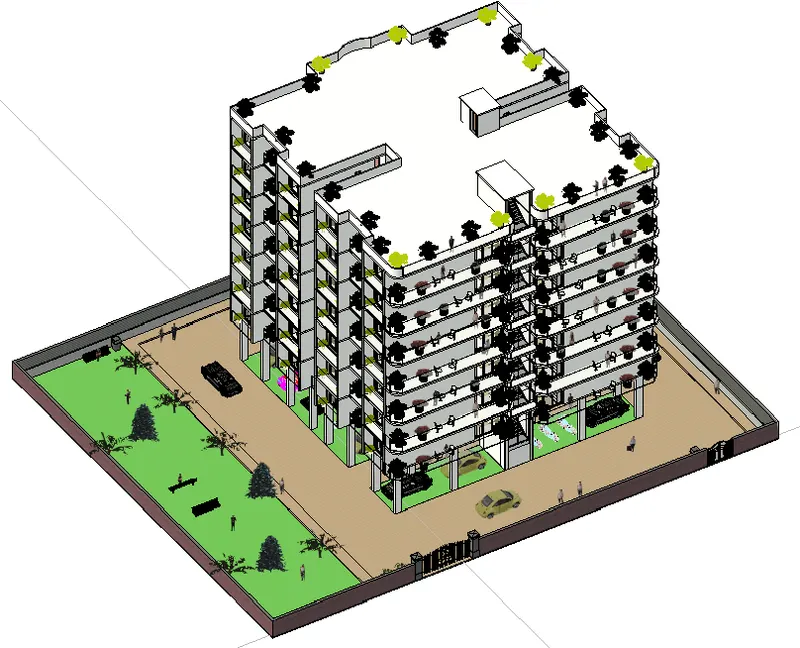
- Clicked First Floor > Selected all elements in drawing area > clicked modify|Element tab > clipboard panel copy > paste by using Aligned to selected Level (levels selected up to 7th floor) > Ok
- clicked in 3d view to check the model copied properly or not.
- Go to stilt Level > Created the boundary wall by taking architechtural wall.
- Vehicle Parking area and Drive way defined by taking floor > architechtural tab > Build Panel > Floor > edit the Boundary > Finish
- To draw Lift & Staircase wall drop down > Wall: Architechtural > selected the 200mm wall in property palatte > c/c of wall selected > Base constraint as stilt & Top constraint as First Floor Level > wall attached to the bottom of floor>Ok
- To create shaft opening for staircase & Lift > Architechture tab > Opening Panel > sketched the shaft opening by dawing lines > Finish opening
- Park area is drawn as we can see in attached image separated by a 100mm non structural wall from the Driveway.
- Clicked on Terrace Level > architechture tab > wall by setting base constraint as Terrace level & top constraint as LMR/Head room level > ok
- Add Floor to Staircase Head room & LMR Roof by sketching the boundary by line tool > Finish
Adding Annotation To Differeent Views in Model
Dimension
- Project browser > Floor Plan > Stilt Floor Plan
- Annotate Tab > Dimension Panel(DI) > drew grid to grid dimension vertically / horizontally.
- Removed leader by Unchecking the leader in property browser.
- Set the Dimension for the wall faces and drew for all the areas.
Room Tag
- Architechture Tab > Room & Area Panel > From Room tag Drop down selected Room
- In case of separation needed (architechture > room separator) room separator used to separate the rooms.
Colorfill Legend
- Clicked Annotate Tab > color fill Panel > Legend > clicked in drawing area beside to the plan to placed the color fill legend
- Choosed room type > room name > ok
Tag by Category
- Annotate Tab >Tag by all >selected doors & windows >ok
- selected the door >right click >selected all instance in entire project >edited the mark in property browser.
- similarly repeated for the window tag.
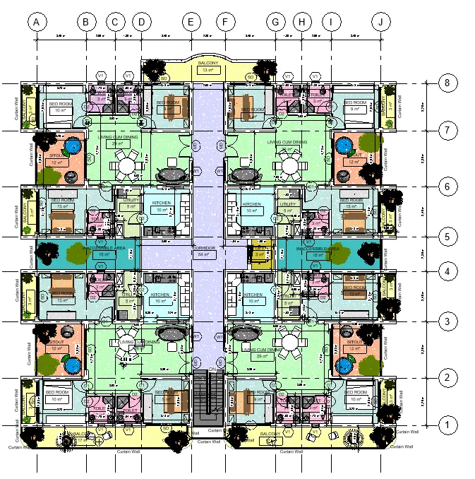
Legend View
- Clicked View tab > Create panel > Legends drop-down (Legend)
- In the New Legend View dialog entered a name as window Legend and selected the view scale as 1:50 > Ok
- Added the desired element symbols to the view > For adding Text clicked Annotate tab > Text panel (Text).
- Similraly Door Legend Created.
Detailed View
- To show the detailing section to be cut in floor plan. View Tab > Create Panel > section
- In the type selector > selected the view type from the list > Placed the cursor at the starting point of the section, dragged through the plan.
- Selected the section head > Right Click > Go to View > as the View opened tagged all elements & dimensioned with detail.
- For stilt side walk level we have drawn a sectiona to get the idea of elevation of the floor as we can see in attached images.
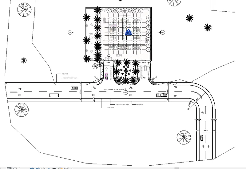
Site Plan - Roads, Side walks, Curbs, site components
- To represent the topography of the site ,created a topo surface in site plan.
- Project Browser > Floor plan > Clicked on site plan > Massing & Site Tab > Model Site Panel > Topo surface > Placed Points in site plan drawing area for creating a surface > Finish
- Adjusted the elevation by edit surface > Points selected & dragged for desired position > Respective Elevation added > Finish
- Massing & site Tab > Building Panel > clicked on Pick line > Value assigned for Offset > Clicked on Building Boundary > Trimmed & Formed a closed loop > Finish
- Massing & Site Tab >Modify Site Panel > property Line > Created Sketching > Finish
- Massing & Site Tab > Modify Site Panel > Label Contour > Sketched a line that intersect one or more contour line
- For Road Go to Annotae Tab > Detail panel > Detail line > Modify| Place detail lines tab > Drew lines for road > By using Fillet Arc provide a curvature to road
- Created road by using Split Surface > massing & site > Modify site panel > Split Surface > The sketching view appeared > pick line selected frpom draw panel > clicked on the detail line drawn before > Finish
- Now the road Surface can be separately selected. To draw side walk we need to split the surface once again. Go to Split surface > selected the surface in site plan which ll consider both road & site surface > The sketching view will be active > Drew by using picking line tool at some Offset distance for side walk > Finish
- Now Separately we can access the side walk surface for any changes. To add surface thickness to side walk Firstly we have to isolate the side walk surface > Go to 3d view > select the side walk surface > From bottom left of revit Home page select the Isolate option > go to File > Export to cad dwg > Next > saved the file in desktop > Leave the temporary Hide/ Isolate mode on and export option selected from the Export dialogue Box
- To add mass to that go to Massing & site tab > Conceptual mass panel > In-Place mass selected > Renamed as Road mass > Insert tab > Import CAD > selected file > Ok > we can see the mass now > Finish Mass
- To add Mass roof > Massing & site > Model by Face Panel > Roof > Edit the roof thickness by editing and duplicating the property > changed the thickness & material to cement sand screed > Ok > Select all by dragging the cursor > Create roof > Clicked on modify > select the roof element in drawing area > assigned a value to level offset
- As the roof mass for side walk created > go to bottom left of Home Page > Reset temprary hide/Isolate
- Go to Realistic view in 3d view we can see the side walk > Now road surface selected > chenged the material in property palette to Asphalt, bitumen > Similarly grass material added to the site topo surface.
- For Curb created a new family Revit > new > Family > Metric profile > Open > drew a profile by using line tool
- select the side walk mass > architechture tab >Build panel > Roof > roof fascia selected from drop down > in edit property > selected the new profile > changed the material> Ok > apply Ok
- Just clicked on side walk face to place the fascia as curb.
- Massing & Site tab > Model Site Panel > Site Components > selected the desire components in type selector > Clicked in drawing area to place it .
- Similarly Parking Component placed in road for landscape view as we can see in attached image.
Schedules (BOQ & Estimates)
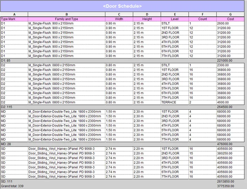
Creating a door schedule
- View > create panel >schedule > schedule/Quantities> Door >Ok
- selected field parameters Type Mark, Family and Type, width, Height,Level, Count, Cost > Ok
- As the door schedule opened, sorting & grouping selected from schedule property and sort by Type Mark parameter >checked in Footer >Then by level > checked in Grand Total (from drop down Title,Count, & Totals selected) > Unchecked itemize every instance >Ok
Creating a Window schedule
- View > create panel >schedule > schedule/Quantities> Window >Ok
- selected field parameters Type mark, Family and Type, width, Height, Level, Count, Cost > Ok
- As the Window schedule opened, sorting & grouping selected from schedule property and sort by Type mark parameter > checked in Footer > Then by level > checked in Grand Total (from drop down Title,Count, & Totals selected)> Unchecked in itemize every instance >Ok
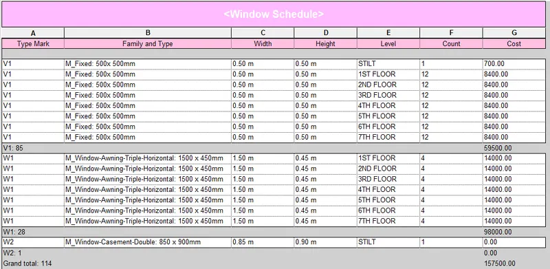
Creating a wall schedule
- View > create panel >schedule > schedule/Quantities> Wall >Ok
- selected field parameters Family and Type, Base constraint, Top constraint, Length, count, Cost > Ok
- As the Wall schedule opened, Field selected from schedule property >Function >Calculated dialogue box opened> Name: Total Cost >Disciple: common>Type: Integer > Formula: Length * Cost > Ok
- sorting & grouping selected from schedule property and sort by Family and Type parameter >checked in Footer > Then by checked in Top Constraint > Then by Lengh > Checked in Grand Total > Unchecked itemize every instance >Ok
- Formatting selected from schedule property > Fields: Length > Checked in show conditional format on sheet > selected calculte Total value from drop down >Ok
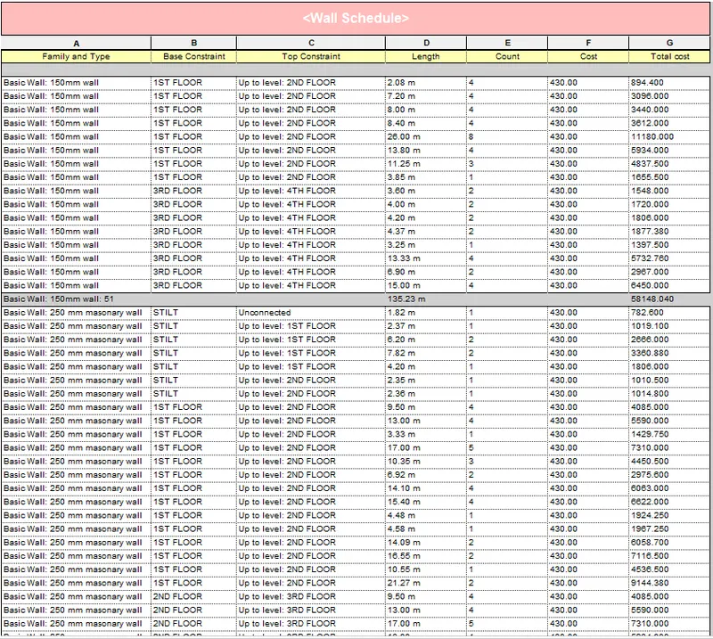
Creating a Furniture schedule
- View > create panel >schedule > schedule/Quantities> Furniture >Ok
- selected field parameters Family and Type, Level, count,Cost> Ok
- sorting & grouping selected from schedule property and sort by Family and Type > checked in Footer > checked in Grand Total > Unchecked itemize every instance >Ok
- Formatting selected from schedule property > Fields: Cost> Checked in show conditional format on sheet > selected Total calculate value from drop down >Ok
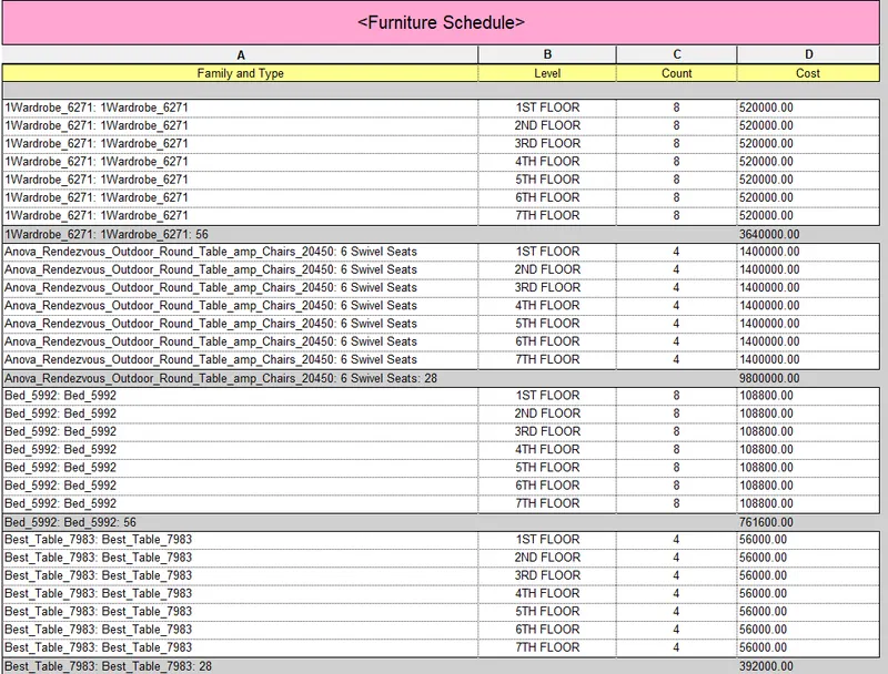
Creating a Wall Material Takeoff
- View > create panel >schedule > Material Takeoff> Category :Wall >Ok
- selected field parameters Material:Name, Base constraint, Top constraint, Material Unit weight > Length > Material:Area > Cost > Ok
- As the Wall material takeoff opened, Field selected from schedule property >Function >Calculated dialogue box opened> Name: Total Cost >Disciple: common>Type: Integer > Formula: Area * Cost > Ok
- sorting & grouping selected from schedule property and sort by Material: Name >checked in Footer > Then by Base constraint > checked in Grand Total > Checked in itemize every instance > Ok
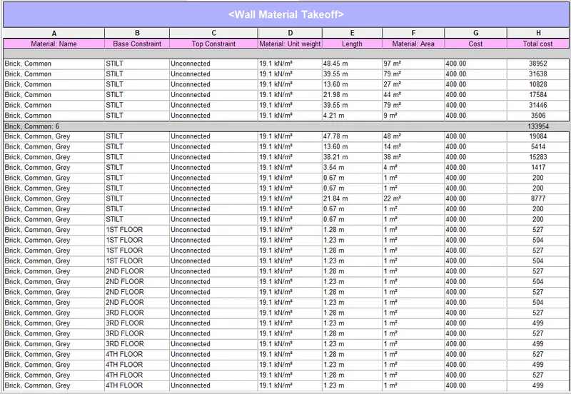
Printing Of Schedules
- Clicked on particular schedule > File > Export > Report > Schedule
- It downloaded as cvs file and edited the file & Printed to pdf.
- The pdfs are attached in File Section.
Printing Of Sheets
-
Project browser >sheets >right click > selected an existing sheet as Title block ( A1 customized sheet )
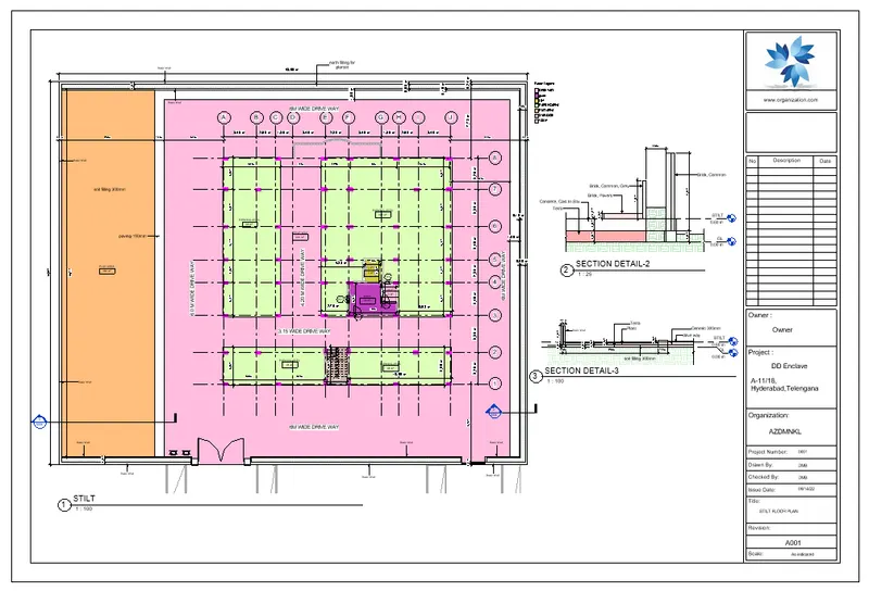
- Renamed the sheet as Stilt Floor plan > Sheet NUmber named as A001 > Dragged the views to place in Sheet > Adjusted the scale.
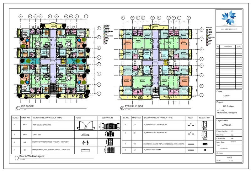
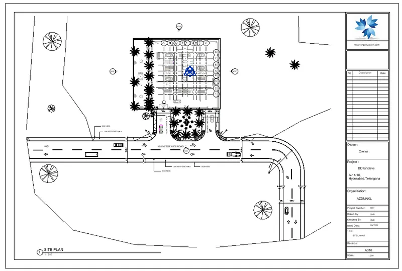
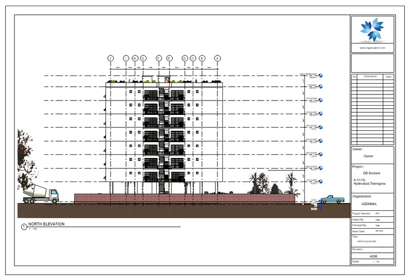
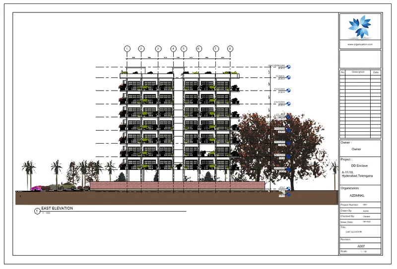
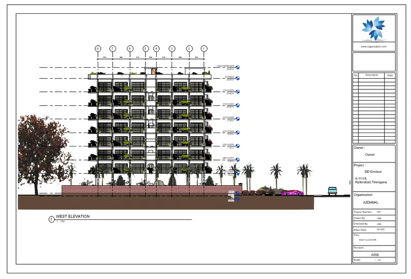
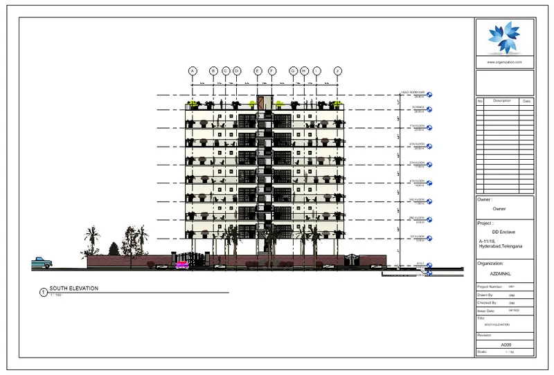
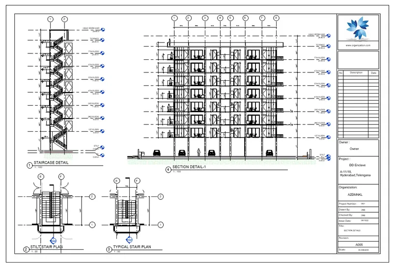
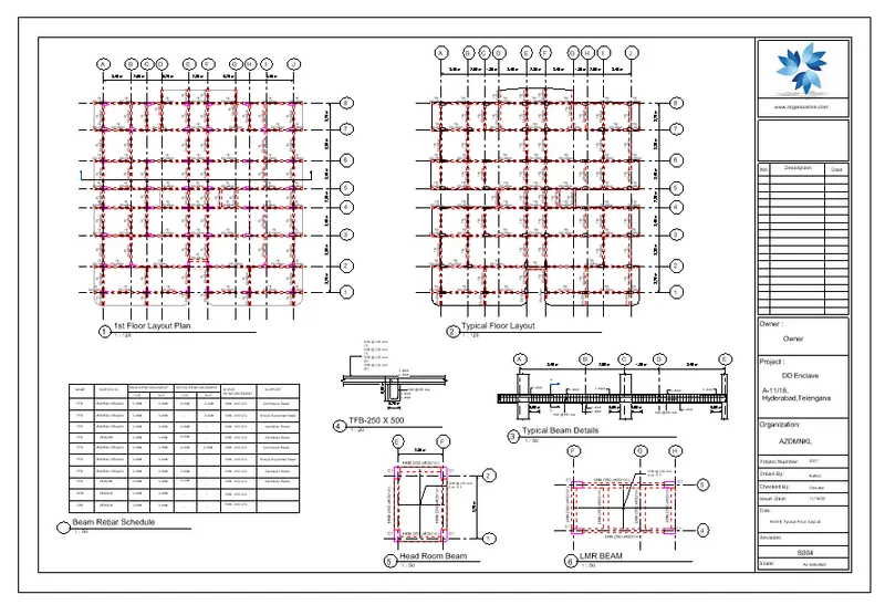
- Similarly Different sheets created by dragging different views & section details as we can see in attached image below.
- For printing the sheet > File Tab > Print
- As we need print to pdf selected the Microsoft pdf printer > Under Pdf range views/Sheets Selected > clicked select > selected views/sheets to print > Print set up done > Ok
- All sheets are shown here & the pdfs are attached in File Section.
3D VIEWS
- Project browser > clicked on siteplan > View tab > create panel> 3D view tool > from drop down camera selected > placed in site plan to a direction and adjust the camera set up for a perfect view.
- Similarly for different views generated by placing camera in different direction.
- Project browser > in 3D view we can find all the views what we created by placing camera.
- Clicked on views > View Tab> Presentation Panel > Render > after render processing done adjusted the image exposure > saved the view > clicked on show model
- After saving we can access the view in project browser > Rendering > views
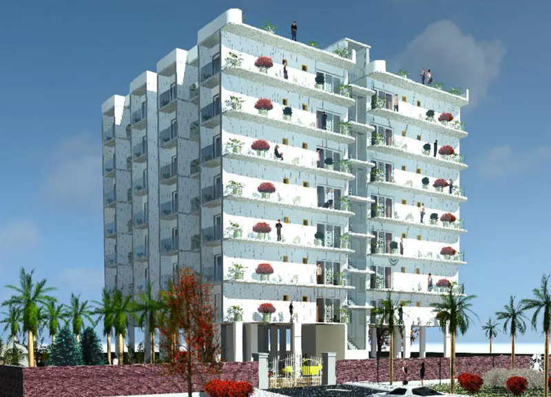
SOUTH WEST VIEW
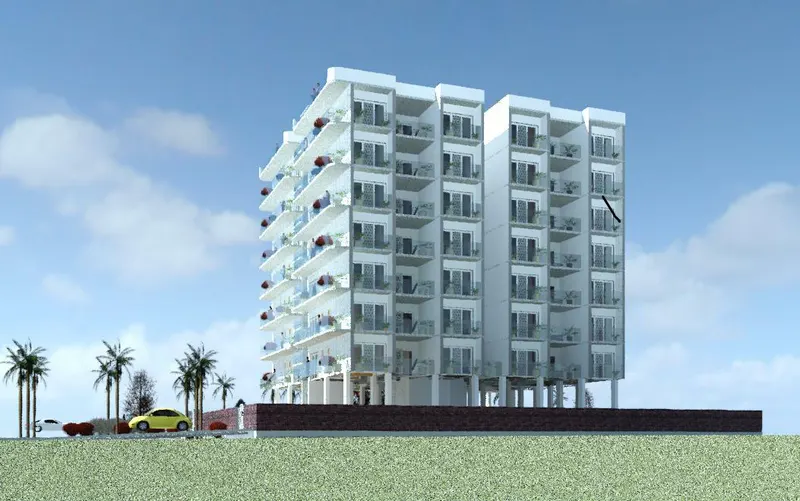
SOUTH EAST VIEW
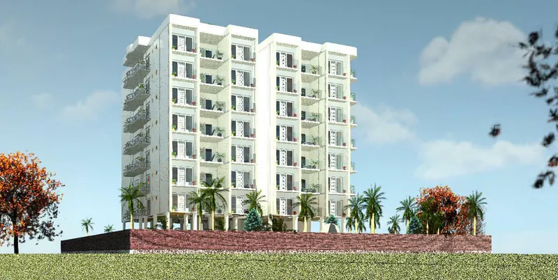
NORTH WEST VIEW
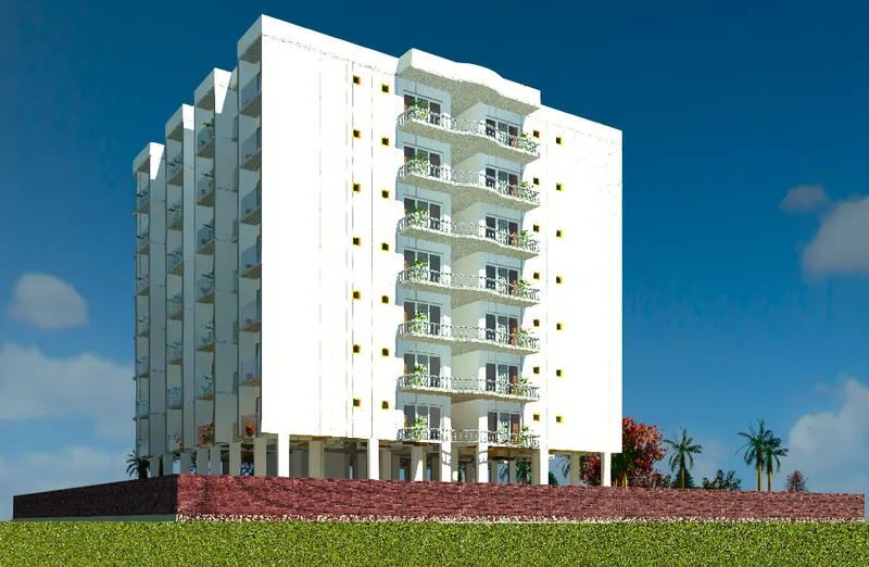
NORTH EAST VIEW
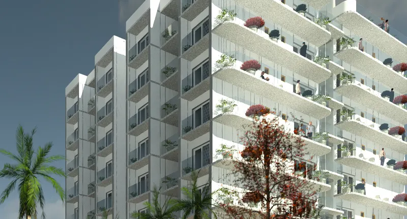 FOCUS VIEW
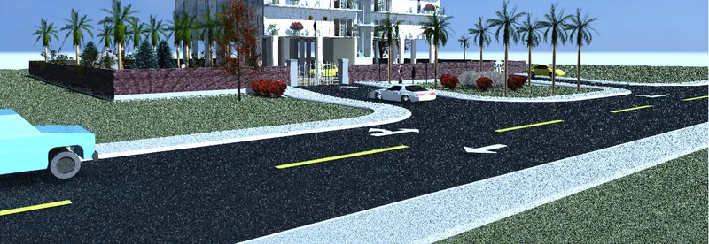
ENTRANCE VIEW
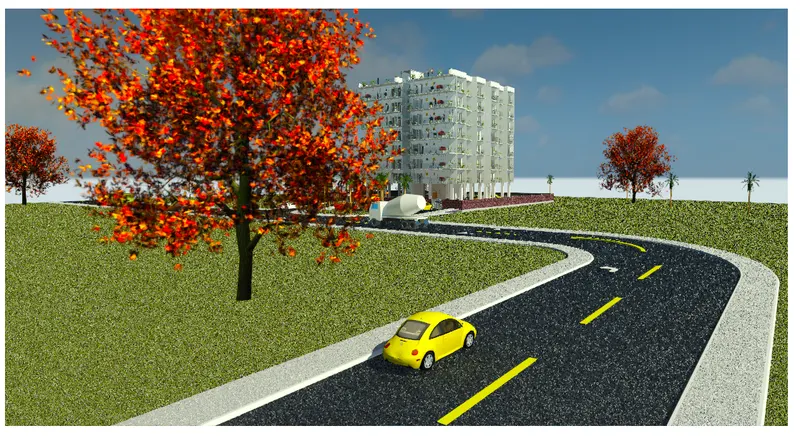
ROAD VIEW
PROCEDURE FOR STRUCTURAL MODEL
Linking of The Architechtural File:
- Revit home page > New Model > structural Template
- Insert > Link revit > browsed arch. file
- Before started working on that the architechtural view pinned.
- south elevation > aligned existing level with the architechtural level
- Structural plan Level-01 > collaborate tab > copy/monitor > select link > section box clicked
- Options > Levels > ok > copy > checked in multiple > selected all in view > filter >checked in chcek none > checked in level > ok > Finish
- Similarly grids copied from architechural file to structural file .Collaborate tab > copy/monitor > select link > section box clicked >Options > grids > ok > copy > checked in multiple > selected all in view > filter >checked in chcek none > checked in grid > ok > Finish
- Levels Named as footing ,plinth Level,First Floor, Second Floor, Third Floor as so on as in Architechtural file.
- Elevation view > levels /grids selected individually > pinned
Placing Of Structural Elements:
Column
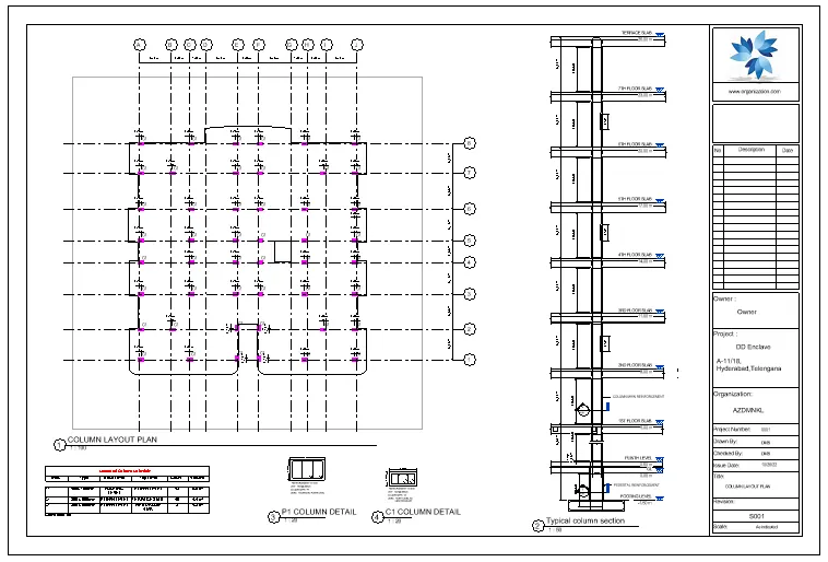
- Clicked Plinth level > structure tab > column > desired size selected at the top of the properties palette > placed individually by aligning to wall location in linking architechtural file.
- Adjusted the column base constraint as Plinth Level & top constraint as Terrace or LMR/Headroom as needed in properties palatte as per requirement.
PedestaL
- Clicked Plinth level > structure tab > column > selected the desired size > placed concentric to column
- Keeping the pedestal base constraint as Footing & top constraint as PLinth Level in properties palatte.
- set the view range in property browser for proper visibility of structural element.
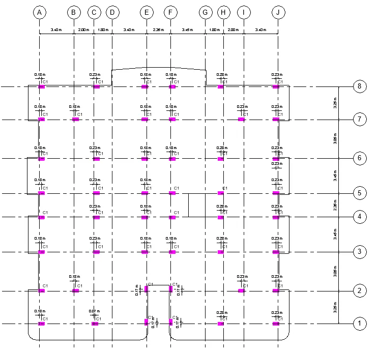
-
Structural wall
-
Clicked structural footing plan > structure tab > structural wall > drew wall for lift pit & plinth boundary wall.
-
set the base constraint & top constraint in properties palatte as per requirement as we can see in attched image below.
-
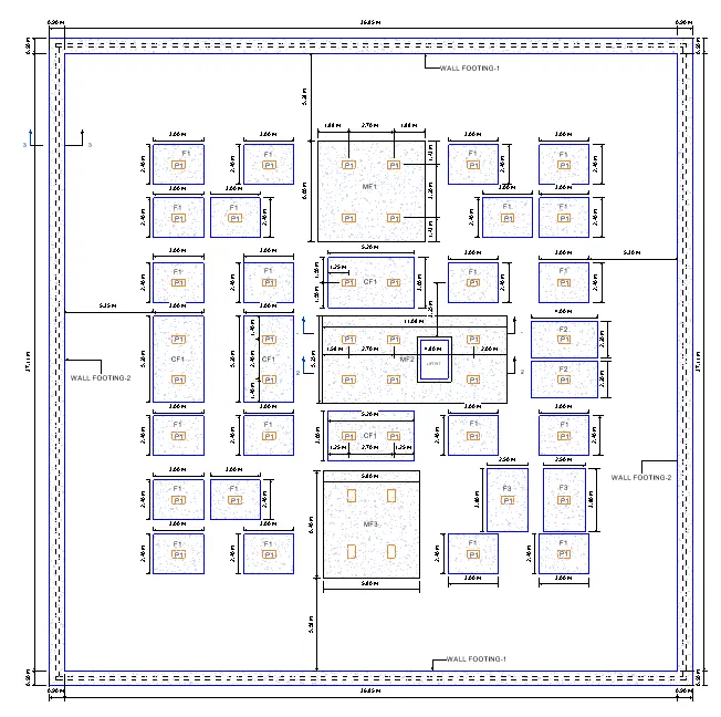
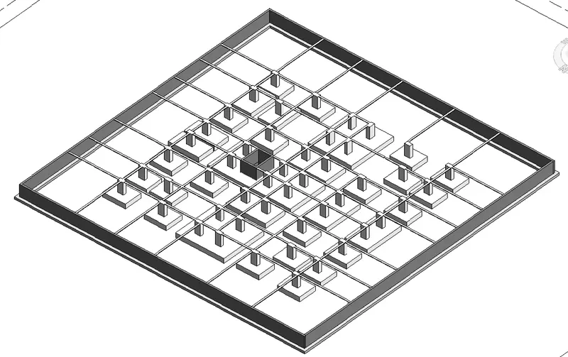
Foundation (Isolated,Combined,Mat)
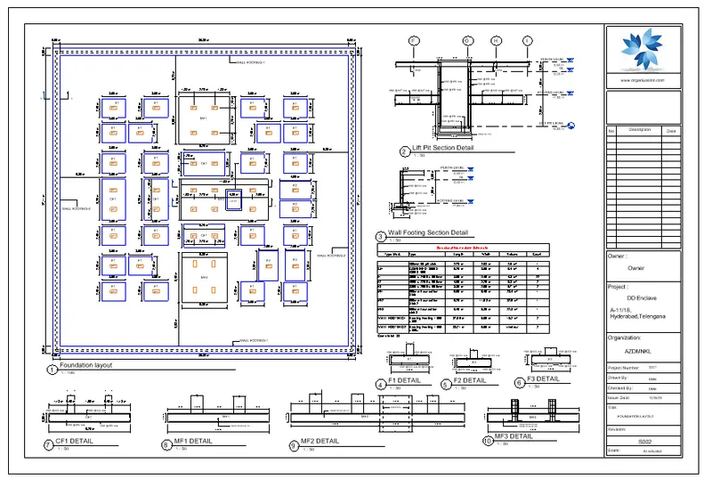
- Clicked Structural footing plan > structure tab > Foundation panel > isolated > size selected > placed concentric to column
- set the base constraint as structural footing & base offset as depth of footing & top constraint as structural footing in properties palatte for proper placing in layout.
- As isolated foundation overlapped with each other so combined footing and Mat footing created as requied as we can see in layout.
- set the view range in property browser for proper visibility of structural element.
wall Foundation
- Clicked Sturctural footing plan > structure tab > Foundation panel > wall > size selected > clicked at the bottom edge of the wall for placing foundation below the wall
- set the base constraint as structural footing & base offset 1' & top constraint as structural footing in properties palatte for proper placing in layout.
- set the view range in property browser for proper visibility of structural element.
- For individual view directed to visibility graphic and uncheck the respective element didn't want to show in view.
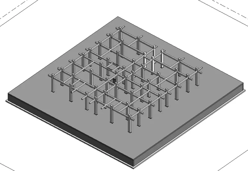
Plinth Beam
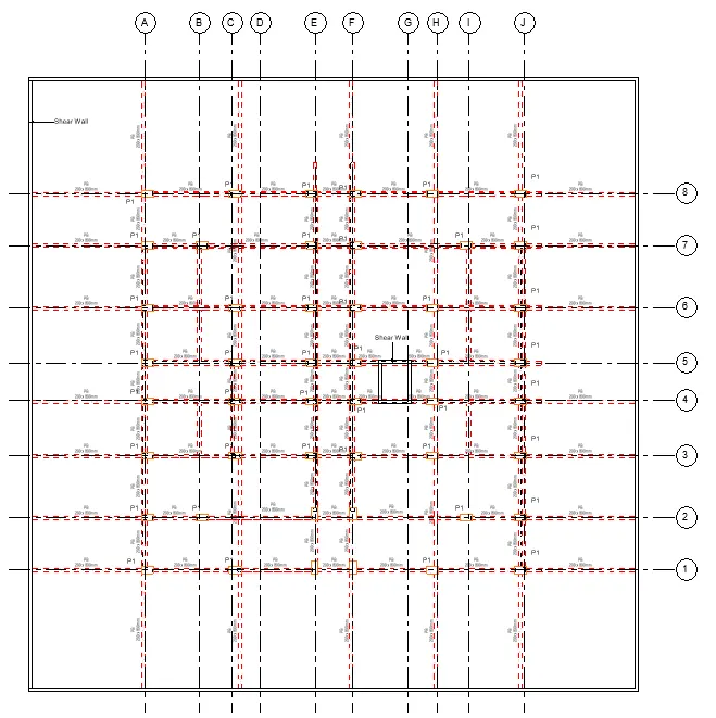
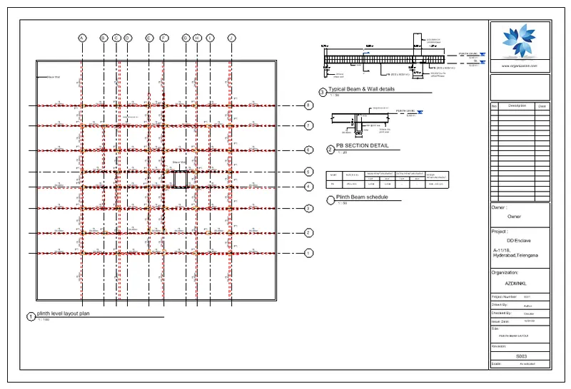
- Clicked plinth level plan > structure tab > beam > size selected > drew pedestal c/c
- set view range in properties palette for visilbility of beams in Plinth level plan
- Beams are tagged by types and mark label together.
Plinth Structural Slab
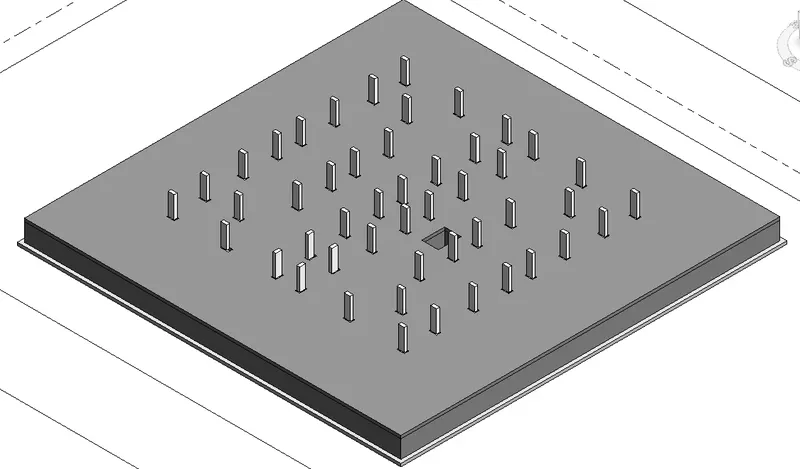
- Clicked plinth level plan > structure tab > Floor structural > desired slab thickness selected > drew the floor by taking rectangle & pedestal surrounding is selected by picking line from modify tab for slab bonding to pedestal > Finish
- 3d view > wall slected in view >right click >select similar instance in view > modify/walls tab modify > wall panel attach Top
- selected the floor slab > Edit Boundary > shaft provided for Lift > Finish
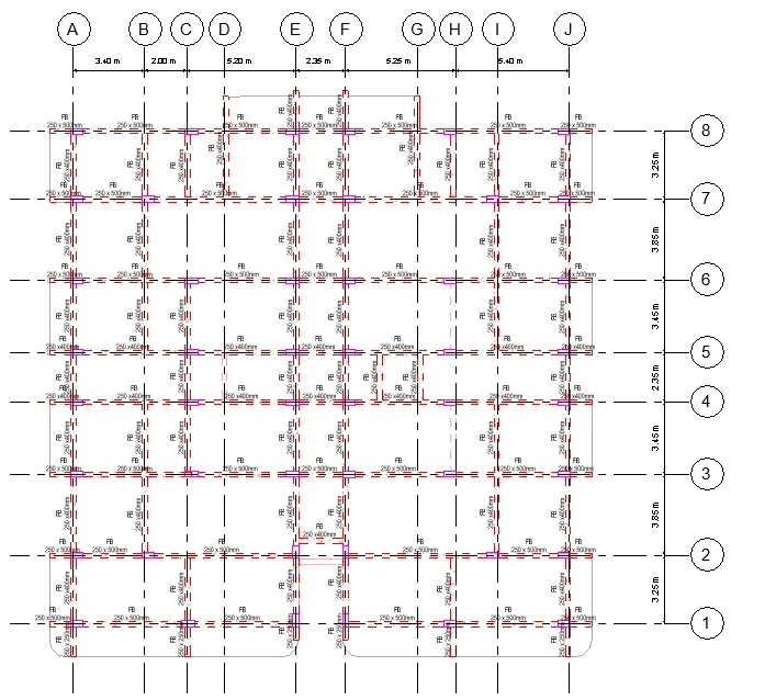
First Floor Beam
- Clicked First Floor level plan > structure tab > beam > size selected > drew column c/c
- set view range in properties palette for visilbility of beams in First Floor plan
- Beams are tagged by types and mark label together.
first floor Structural Slab
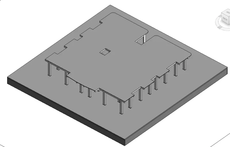
- Clicked first floor level plan > structure tab > Floor structural > desired slab thickness selected > drew the floor by clicking pick line & column surrounding is selected by picking line from modify tab for slab bonding to column > Finish
- selected the floor slab > Edit Boundary > shaft provided for staircase > Finish
- Dragged the lift shaft up to the respective level.
Copy Structural element from one level to next level
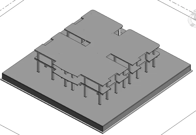
- Clicked first floor level plan > selected one column> right click > select all instance in view > changed the top constrain to Terrace or LMR/Head Room as required.
- Clicked first floor level plan > selected all in view> filter > checked in check none > checked in beam > apply >ok > copy with clipboard > paste into assigned selected level (second floor level)
- Opened second floorlevel to recheck the position of beams and deleted some beams as we didn't need in second floor plan.
- Structure tab > Floor structural > desired slab thickness selected > drew the floor by clicking pick line & column surrounding is selected by picking line from modify tab for slab bonding to column > Finish
- As second floor plan is typical upto Terrace so sturucural element (Beam & slab) slected and copied to selected level ( From Third floor to Terrace floor).
- For staircase, shaft level increased just above the terrace level by dragging the shaft box extension arrow upward in 3d view.
Addition of Reinforcement to Structural Element
As structural model created let's opt for placing of reinforcement.
- Structure > Reinforcement Panel > Rebar Cover setting > Add > Renamed the description as Foundation /Wall/Column/Beam/Slab cover and value defined.
Placing of Rebar in Isolated /Combined / Mat footing & wall foundation
- Clicked structural footing plan > Drew a section perpendicular to footing > section selected > right click > Go to view
- Structure > Reinforcement Panel > Cover > clicked on footing edge > from drop down footing cover selected
- Structure > Reinforcement Panel > Rebar > host selected > clicked on desired rebar shape (loaded rebar shape from library) > selected desire rebar type in type selecter at the top of property palatte > defined the plane (current work plane) in placement plane panel > defined orientaion (parallel to work plane) in placement orientation panel > clicked in footing section view within the cover limit for placing the main bar.
- For placing rebar in minor direction rebar type selected > clicked on desired rebar shape > defined the plane (current work plane) in placement plane panel > defined orientaion (perpendicular to cover) in placement orientation panel > clicked in footing section view for placing the distribution rebar.
- In rebar instant parameter rebar hook added at start and end of the rebar.
- Hook length changed by editing rebar properties.
- Layout > maximum spacing > spacing value added
- since rebar was not visible in structural plan, pick the rebar by cursor >view visibility in property palette > checked in structural plan
- checked in 3d view > view changed to fine & wireframe for clear visibility of rebar.
- Similarly rebar added for combined footing. In case of mat Footing Area reinforcement picked > boundary selected > major direction picked > Rebar size selected in properties palette > Finish
- since the rebar was not visible point the rebar in cursor > override graphics> checked in 3d and plan view.
- As placed rebar for isolated footing similarly placed for wall footing.
Placing of Rebar in Pedestal/Column/shear wall
- Structure > Reinforcement Panel > Cover > clicked on pedestal edge > from drop down column cover selected
- Drew a section in footing section view transversly to pedestal > section selected> right click > go to view > plan view of the individual pedestal opened
- Structure > Reinforcement Panel > Rebar > clicked on rebar shape > selected desire rebar type in type selecter at the top of property palatte > defined the plane (current work plane) in placement plane panel > defined orientaion (parallel to work plane) in placement orientation panel > clicked in pedestal plan view within the cover limit for placing the Tie.
- For placing main rebar, type of rebar selected > clicked on desired rebar shape > defined the plane (current work plane) in placement plane panel > defined orientaion (perpendicular to cover) in placement orientation panel > clicked in pedestal plan view for placing the main rebar
- Footing section view opened & extended the pedetal main rebar towards the footing.
- In rebar instant parameter rebar hook added at start and end of the rebar.
- Hook length changed by editing rebar properties.
- Layout > maximum spacing > spacing value added
- checked in 3d view > view changed to fine & wireframe for clear visibility of rebar
- As placed rebar for pedestal similarly placed for column.
- For structural wall the procedure is same however straight rebar provided as horizontal rebar on both sides rather than stirrup as in column.
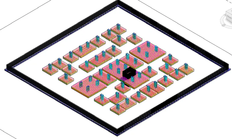
- Column rebars & footing rebars selected > modify tab > create group > copy the group rebar system to all similar footing to place the rebar in whole plan.
Placing of Rebar in Beam
- Clicked plinth level plan > Drew a section perpendicular to beam > structure tab > (beam) > Cover > select host (Beam) > Beam cover selected from dropdown.
- structure > Rebar > clicked on rebar shape > selected desire rebar type in type selecter at the top of property palatte > defined the plane (current work plane) in placement plane panel > defined orientaion (parallel to work plane) in placement orientation panel > clicked in beam section view within the cover limit for placing the stirrup.
- structure > Rebar > clicked on rebar shape > selected desire rebar type in type selecter at the top of property palatte > defined the plane (current work plane) in placement plane panel > defined orientaion (perpendicular to cover) in placement orientation panel > clicked in beam section view within the cover limit for placing the main bar in top & bottom. (set the rebar number-3 to place two rebar at a time.
- Stirrup selected > layout > maximum spacing > value added & checked in 3D view.
- Copied rebar to all other beams .Length & stirrup number adjusted by stretching the rebar extension arrow.
- Similarly rebar added to first floor & othertypical floor beams.
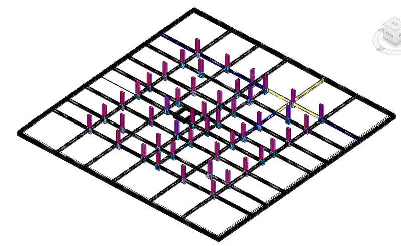
PLINTH BEAM
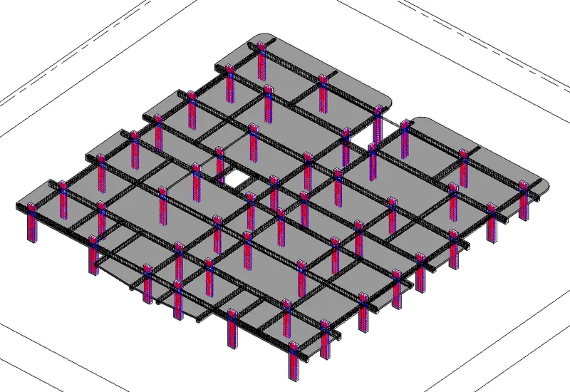
FLOOR BEAM
Placing of Rebar in Plinth Floor Level
- Clicked on plinth level > structure > Cover > clicked on floor > slab cover selected from dropdown.
- structure > select the host (floor) > rebar > clicked on rebar shape (straight bar) > selected desire rebar type in type selecter at the top of property palatte > defined the plane (current work plane) in placement plane panel > defined orientaion (parallel to work plane) in placement orientation panel > placed horizontally in one click & then vertically in 2nd click (in rebar set single rebar to be selected) within the cover limit.
- Drew perpendicular section in both direction. selected section > right click > go to view> select the rebar > layout > number with spacing> as rebar was placing vertically so selected the rebar >modify panel> rotate> place in center > rotated horizontally
- As the rebar orientation set properly >layout > maximum spacing > value added. similar procedure adopted for distribution bar .
- section view opened > adjusted the bottom bar (B1,B2) by moving the arrow upward/downword as per the length of span.
- section view > copied the bottom rebars (B1,B2) > modify panel >mirror by pick axis > click at the center of slab axis to mirror the rebar as top bar (T1,T2)
- checked in 3d view and adjusted the view (fine / wire frame) for clear visibility.
- Duplicate the view with detailing twice and renamed as Bottom reinforcement & Top reinforcement individually.
- Clicked Bottom reinforcement structural plan > VG > Filter > unchecked the top rebar (T1,T2)> apply> ok
- similarly Clicked top reinforcement structural plan > VG > Filter > unchecked the bottom rebar (B1,B2)> apply> ok
- selected rebar >present panel > show in middle (this applied for bottom & top reinforcement)
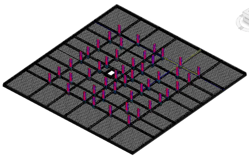
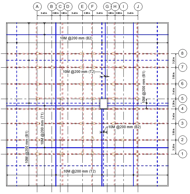
PLINTH FLOOR SLAB REINFORCEMENT
Placing of Rebar in 1st Floor& Typical level slab Level
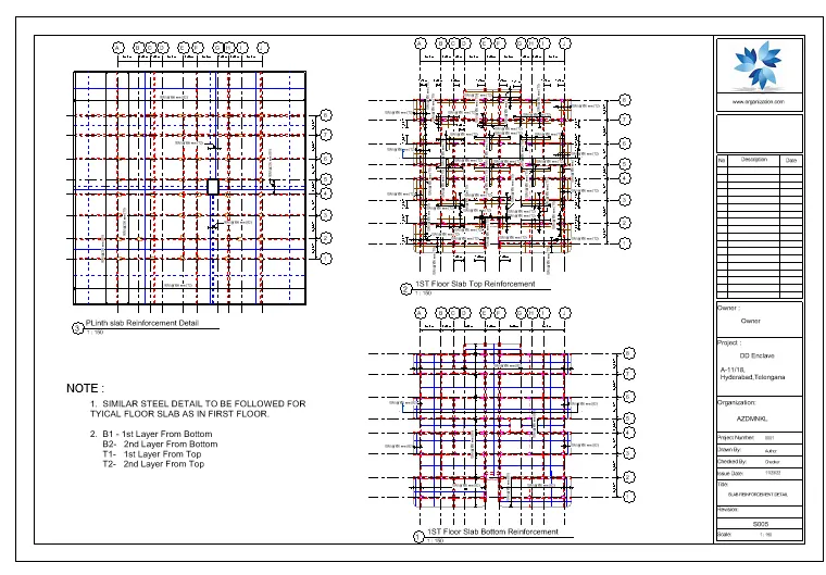
- Clicked 1st Floor Level & similar procedure adopted for rebar placement as done in plinth level.
- Annotate > model line > drew to show curtailment of top rebar >adjusted the rebar length by dragging the rebar extension arrow.
- selected rebar >present panel > show in middle or select< select none < clicked in on rebar which wanted to show.
- Annotate > multi-Rebar annotation > clicked on rebar > placed & selected >edit lable > parametric properties kept which wanted to show in rebar tag
- selected dimension> modify panel >selected dimension > unchecked show dimension text in edit properties of dimension.
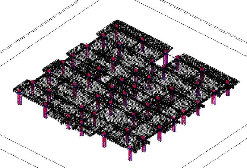
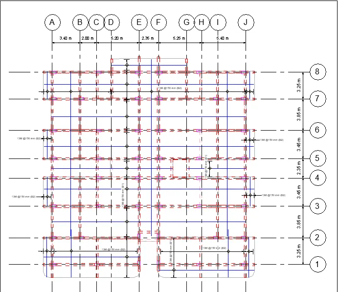
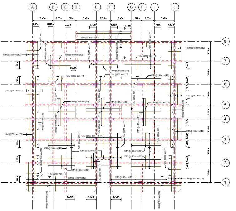
FIRST FLOOR SLAB BOTTOM STEEL FIRST FLOOR SLAB TOP STEEL
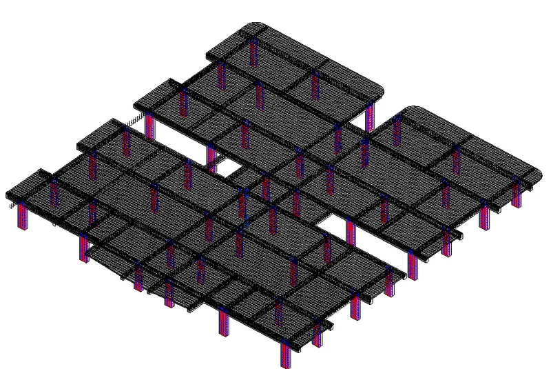
TYPICAL FLOOR SLAB
Detailing Of Reainforcement
- Clicked Footing level > drew section along the lift pit > by double clicking the tail section view opened > renamed it as Lift pit section detail > all annotation done for detailing.
- Annotate tab > aligned dimesion > showed dimension
- Annotate > tag all > checked in structural foundation/Pedestal/ Column.
- clicked on section view for footng detail >right click >renamed as foundation detail > opened >annotate >Tag all > checked in structural rebar > ok
- Tags are adjusted by adding leader & Placed properly.
- Similarly Plinth level ,First Floor level plan opened > Duplicate the view for detailing > Beams are tagged by Mark & type name.
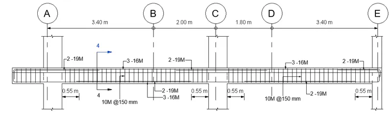
- Beam reinforcement details have also shown by tagging rebar.
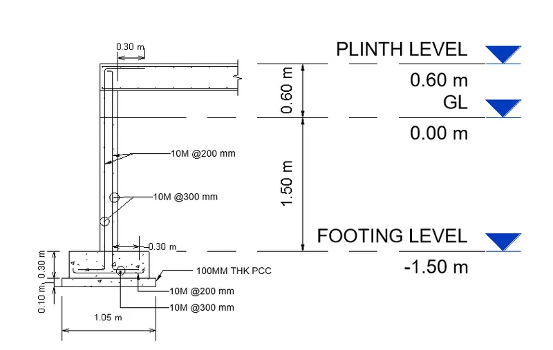
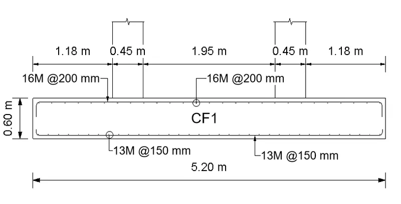
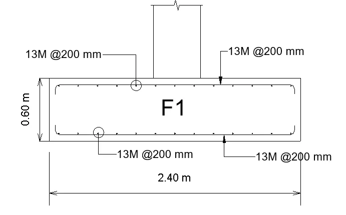
TYPICAL FOOTING SETION CF1 FOOTING DETAIL F1 FOOTING DETAIL
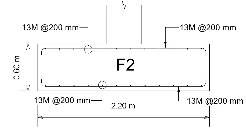
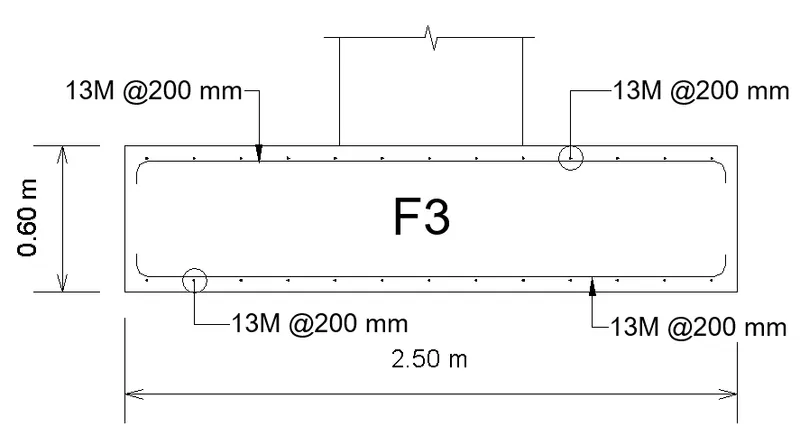
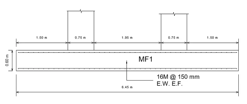
F2 FOOTING DETAIL F3 FOOTING DETAIL MF1 FOOTING DETAIL
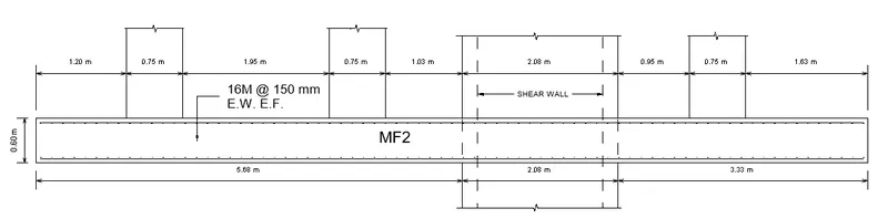
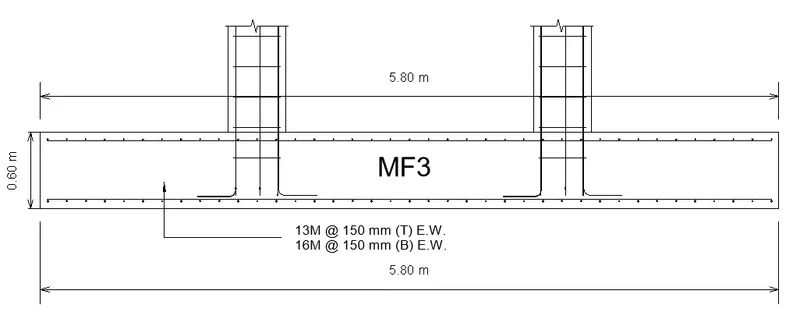
MF2 FOOTING DETAIL MF3 FOOTING DETAIL
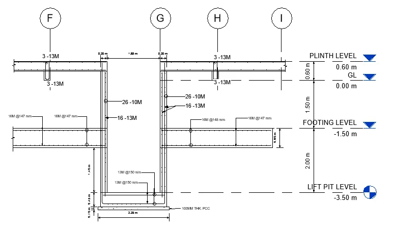
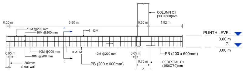
LIFT PIT WALL DETAIL PLINTH BEAM L/S DETAIL
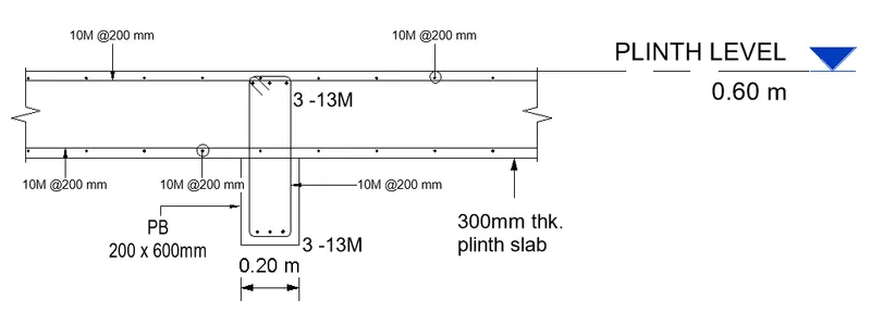
LIFT PIT WALL DETAIL PB- 200 X 600
Schedules (BOQ & Estimates)
Creating Foundation schedule
- View > create panel >schedule > schedule/Quantities> Structural Foundation >Ok
- selected field parameters Type Mark, Type, Length, Width, Volume , Count, Cost/cum > Total cost > Ok
- As the Foundation schedule opened, Field selected from schedule property >Function >Calculated dialogue box opened> Name: Total Cost >Disciple: common>Type: Integer > Formula: Volume * Cost > Ok
- Sorting & grouping selected from schedule property and sort by Type Mark parameter >checked in Footer > checked in Grand Total > checked in itemize every instance > Ok
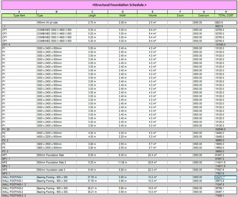
Creating Column schedule
- View > create panel >schedule > schedule/Quantities> Structural Column >Ok
- selected field parameters Mark, Type, Base Level, TopLevel, Count, Volume , Cost , Total Cost > Ok
- As the Column schedule opened, Field selected from schedule property >Function >Calculated dialogue box opened> Name: Total Cost >Disciple: common>Type: Integer > Formula: Volume * Cost > Ok
- Sorting & grouping selected from schedule property and sort by Top Level parameter > checked in Footer > checked in Grand Total (from drop down Title,Count, & Totals selected) > Checked in itemize every instance >Ok
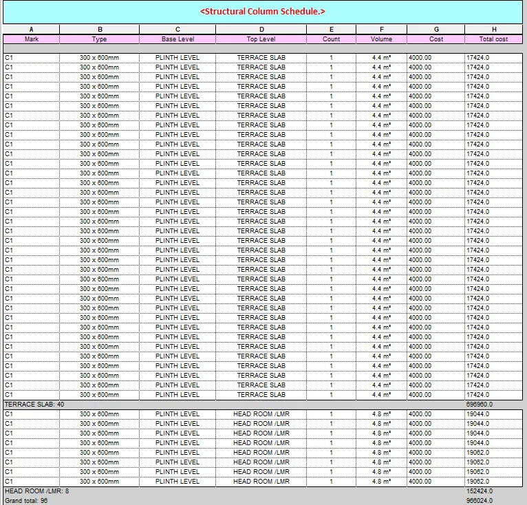
Creating Framing schedule
- View > create panel >schedule > schedule/Quantities> Structural Framing >Ok
- selected field parameters Type, Mark, Length , Count , Volume , Cost/ cum >Ok
- As the Framing schedule opened, Field selected from schedule property >Function >Calculated dialogue box opened> Name: Total Cost > Disciple: common> Type: Integer > Formula: Volume * Cost > Ok
- Sorting & grouping selected from schedule property and sort by Top Level parameter > checked in Footer > checked in Grand Total (from drop down Title,Count, & Totals selected) > Checked in itemize every instance >Ok
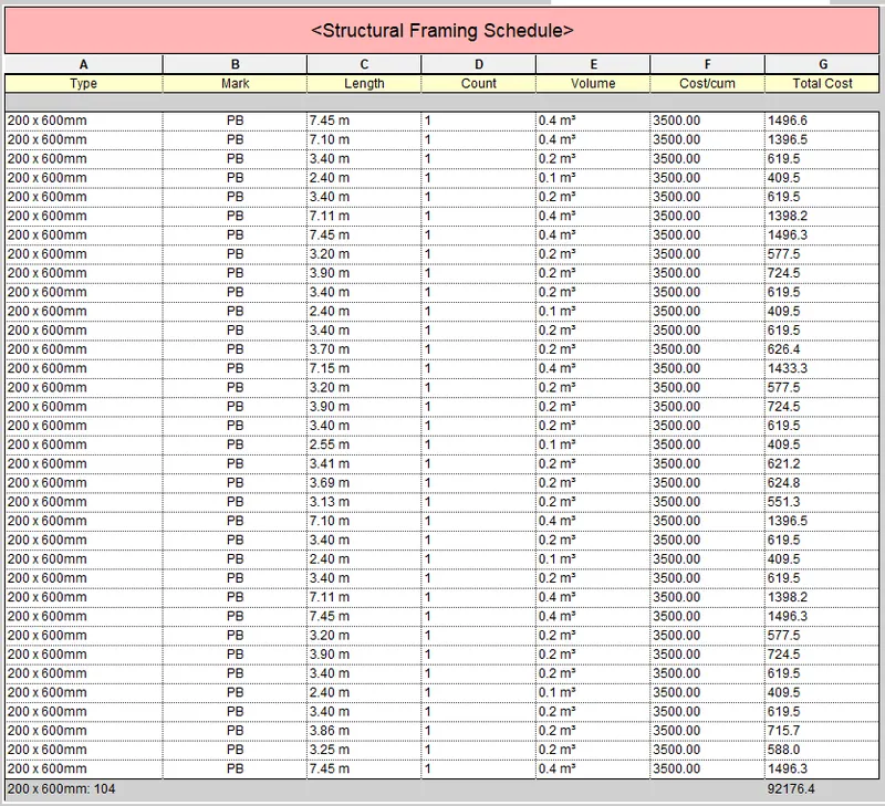
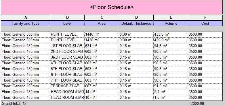
Creating Floor schedule
- View > create panel >schedule > schedule/Quantities> Structural Floor >Ok
- selected field parameters Family and Type, Level, Area , Default Thickness , Volume , Cost >Ok
- Sorting & grouping selected from schedule property and sort by Level parameter > checked in Grand Total (from drop down Title,Count, & Totals selected) > Checked in itemize every instance >Ok
Creating Rebar schedule
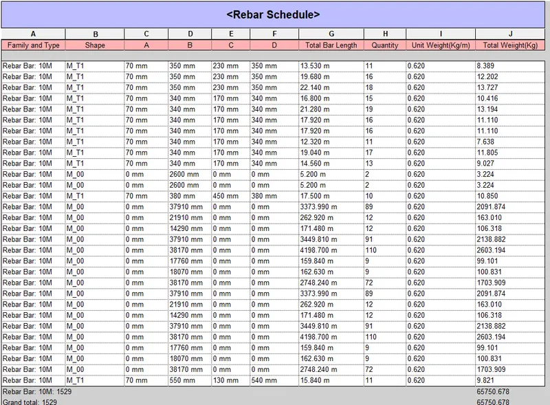
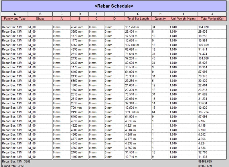
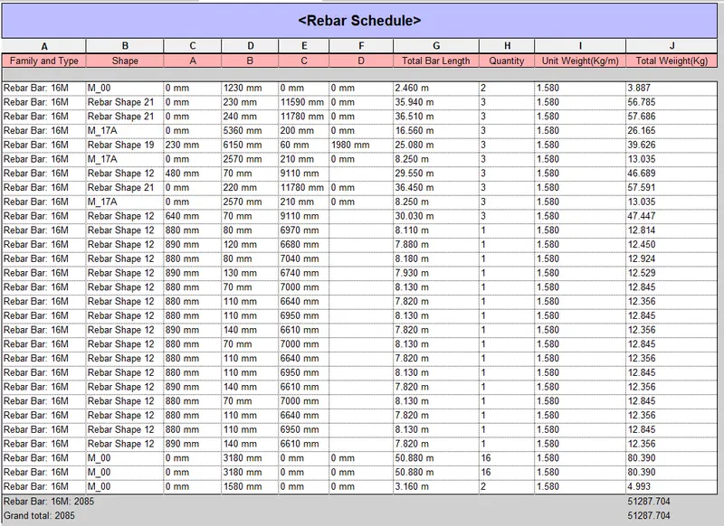
- View > create panel >schedule > schedule/Quantities > Structural Rebar>Ok
- selected field parameters Family and Type, Shape , A,B,C,D > Total Bar Length > Quantity >Ok
- Field > New Parameter created as Name :Unit weight as Type parameter > Discipline : Structural > Type of parameter : Mass per unit length >Group parameter under Data > Ok
- Go to structural Layout > clicked on Rebar > In property palette Edit the rebar and added the unit weight for every rebar as we can see in attached image.
- As the Rebar Schedule opened, Field selected from schedule property >Unit weight added > Function >Calculated dialogue box opened> Name: Total weight > Disciple: Structural > Type: mass > Formula: Total bar Length * Unit Weight > Ok
- Sorting & grouping selected from schedule property and sort by Family Type parameter > checked in Footer > checked in Grand Total (from drop down Title,Count, & Totals selected) > Checked in itemize every instance > Ok
Printing Of Schedules
- Clicked on particular schedule > File > Export > Report > Schedule
- It downloaded as cvs file and edited the file & Printed to pdf.
- The pdfs are attached in File Section.
Printing Of Sheets
-
Project browser >sheets >right click > selected an existing sheet as Title block ( A1 customized sheet )
- Renamed the sheet as Stilt Floor plan > Sheet NUmber named as S001 > Dragged the views to place in Sheet > Adjusted the scale.
- Similarly Different sheets created by dragging different views & section details as we can see in attached image below.
- For printing the sheet > File Tab > Print
- As we need print to pdf selected the Microsoft pdf printer > Under Pdf range views/Sheets Selected > clicked select > selected views/sheets to print > Print set up done > Ok
- All sheets are shown here & the pdfs are attached in File Section.
3D VIEWS
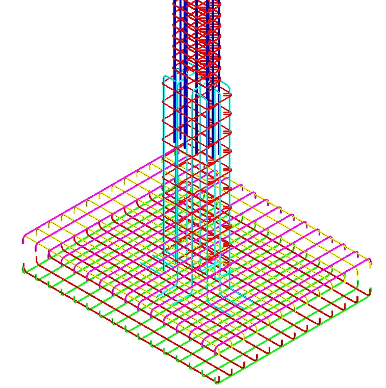
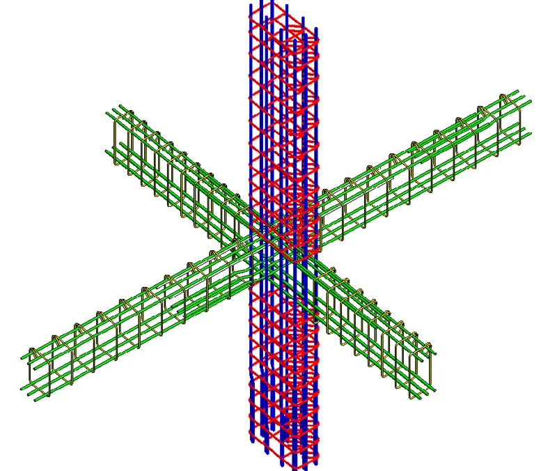
- Project browser > clicked on column plan > one column selected > clicked on section box in view tab > As the view opened took a perfect rebar view as we can see in attched image.
- Similarly did for shear wall & Column & beam section.
PRINTING OF FLOOR PLAN INCLUDING BOTH TRADE ELEMENT
- For Linking architechtural & structural file opened the architechtural file. Structurtal file has pinned before linking.
- In architechtural file go to Manage Tab > Manage Project Panel > Manage Links > Default Revit tool has selected > Clicked on Add > Browsed the revit structural file >Files of type as *rvt. > positioning as auto-internal origin to inernal origin > Open
- selected all by cross selection > Filter > Checcked in none > Revit link checked in > OK > pinned it.
- After opened the floor plan and reviewd the coordination plan as attached.