Project 2
AIM:
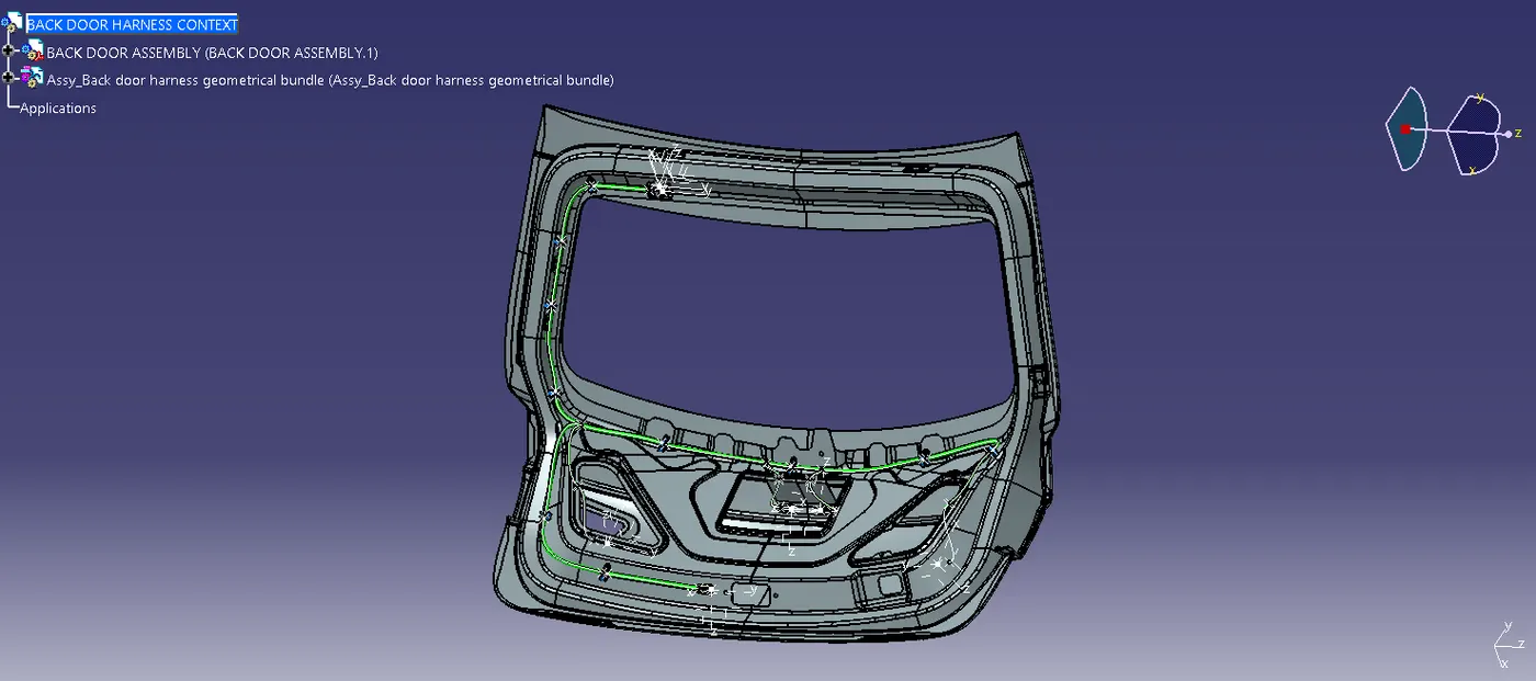
To Route the Wiring harness on given car body and to prepare flatten view drawing in CATIA V5.
OBJECTIVES:
- Route the wiring harness in given back door.
- Prepare flatten view drawing in CATIA V5.
- Apply all packaging rules and industry best practcies.
- Apply protection coverings as required.
- Provide all necessary reports like clearance, clipping/clamping selection,harness fixing requirements,harness continuity,assumptions if any along with CATIA 3D data.
PACKAGING RULES MADE IN THIS PROJECT:
- Provide clips/clamps as per requirement.
- Make sure that there is no any fauling case while designing the wire harness.
- Routing through small structural holes and openings shall be avoided.
- Additional clips/clamps may be used to avoid fauling case.
- Give additional slack if needed. 5-10% slack is sufficient.
- Avoid routing over bolt and bolted joints to avoid harness puncture.
- Avoid routing on sharp edges or else provide protection over the harness.
- Wiring harness routing should provide ease in manufacturing, accessibility,easy removal and easy maintenance of attached equipment and wiring harness.
- Follow the clearance distance and keep away the harness from heat generation components.
- Protection should be provided as needed according to surrounding temperature.
- Avoid direct support for harness on fuel lines routed in the engine.
- Use plastic guiding channels if needed.
- Branch length should be greater than 50mm.
- Limit branches to 4 only.
- Minimum distance between two branch points should be at least 50mm.
- Minimum distance between clip and branch point should be at least 25mm.
- Avoid too many sheet metal brackets on the engine. Try to use available threaded bosses on the engine or demand for it.
- The wiring harness should be easy to assemble and easy to access.
- While using dummy connectors, ensure that whatever positions you are defining that are practical. Bundle diameters and another placements can be defined properly for the wire harness routing.
- Avoid the harness routing and clipping in blind zone of operator during harness assembly or in service.
ASSUMPTIONS:
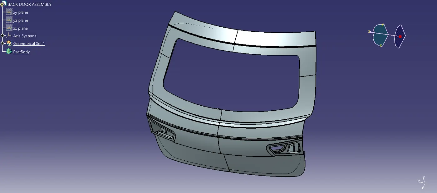
- In the given car back door the two tail lights, the two number plate lights and one parking sensor will have to be wired and connected to the car electrical main system.
- For the two tail lights and parking sensor, we will be using three Deutsch 4-pole connectors(C-DT06-4S). For the two number plate lights, we will be using two Deutsch 2-pole connectors (C-DT06-2S). The car back door body is also having an interconnection connector which will connect the car back door wiring harness to the main body harness of the vehicle. We will be using a 12-pole electrical connector (C-776438-4) with a mounting clip feature as an interconnection connector.
- The bend ratio for all the bundle segments is considered to be 1.4.
- For mounting purpose, we will be using 9 P-Clamps and 4 Omega clips.
STEP 1 : CREATING BACK DOOR HARNESS CONTEXT:
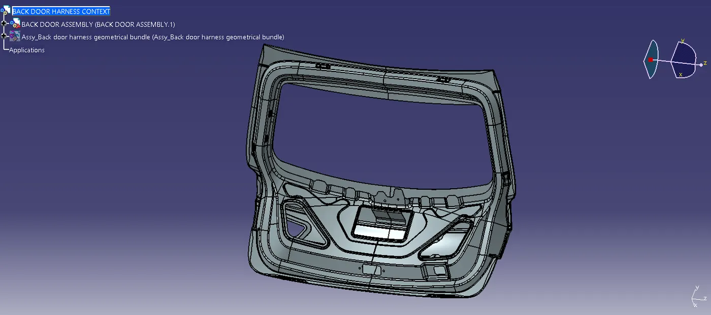
Fig:1
- The Back door file is downloaded from the given CAD data. Then new product file is created and renamed it as Back door harness context, which contains all the assemblies as shown in the above fig:1.
- A Context Assembly will contain Back door Assembly data and Assembly back door Harness Geometrical Bundle.
STEP 2 : DEFINING ELECTRICAL DEVICES IN ELECTRICAL PART DESIGN WORKBENCH:
4 POLE CONNECTOR ( C-DTO6-4S):
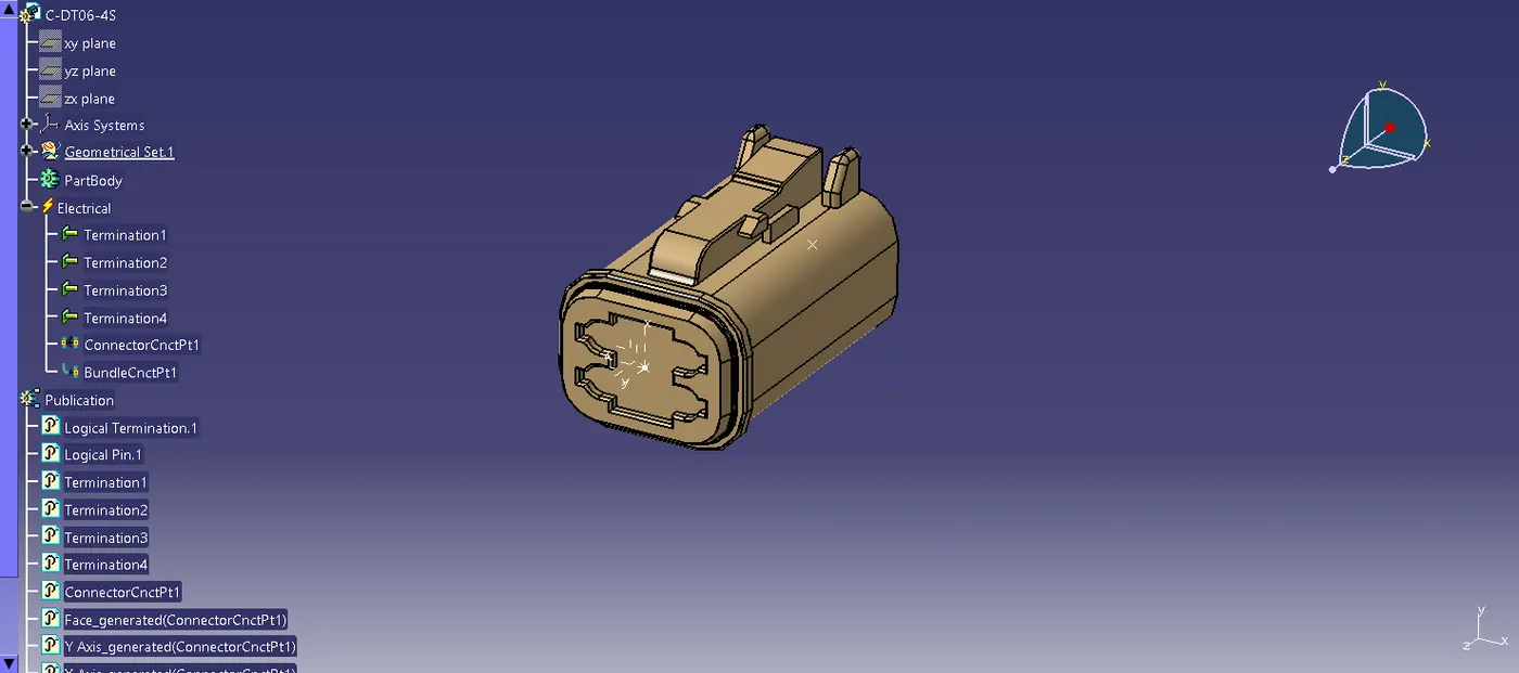
Fig : 2
- The connector C-DT06-4S which have 4 terminals are selected according to the requirement. The CAD data is downloaded from te.com . Which is electrically defined by using electrical part design workbench.
- The connector connection point and the bundle connection point are also defined.
2 POLE CONNECTOR ( C-DT06-2S) :
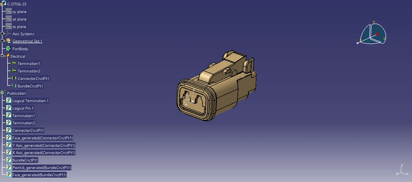
Fig: 3
- The connector C-DT06-2S which have 2 terminals are selected according to the requirement.The CAD data is downloaded from te.com . which is electrically defined by using electrical part design workbench.
- The connector connection point and the bundle connection point are also defined.
INTERCONNECTION CONNECTOR (C-776438-4):
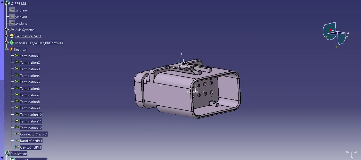
Fig :4
- The Interconncetion connector C-776438-4 which has 12 terminal is electrically defined using electrical part design workbench. The CAD data is downloaded from te.com .
- The connector connection point, bundle connection point and the cavity connection point are defined.
P CLAMP:
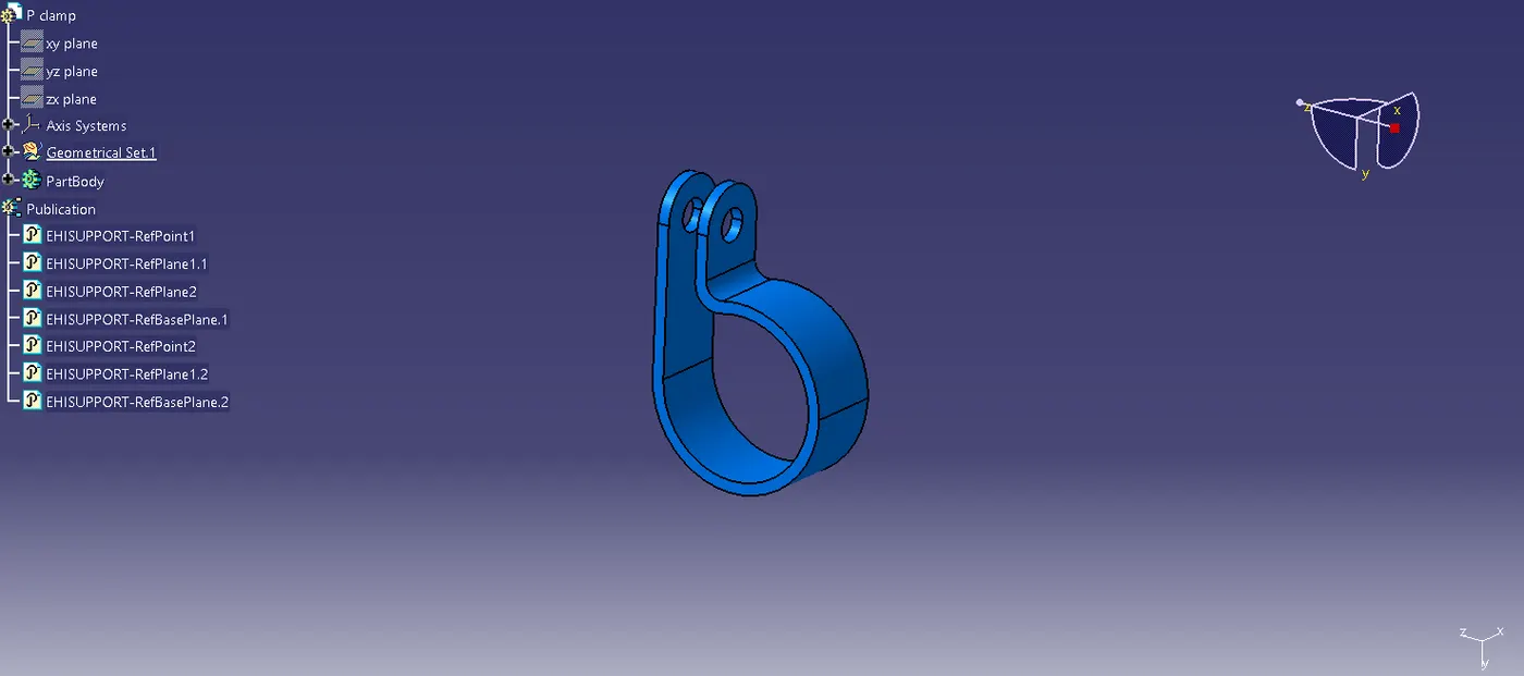
Fig:5
- The P clamp is defined as a support in electrical part design workbench. The entry,exit planes and points also the base plane are defined.
OMEGA CLIP:
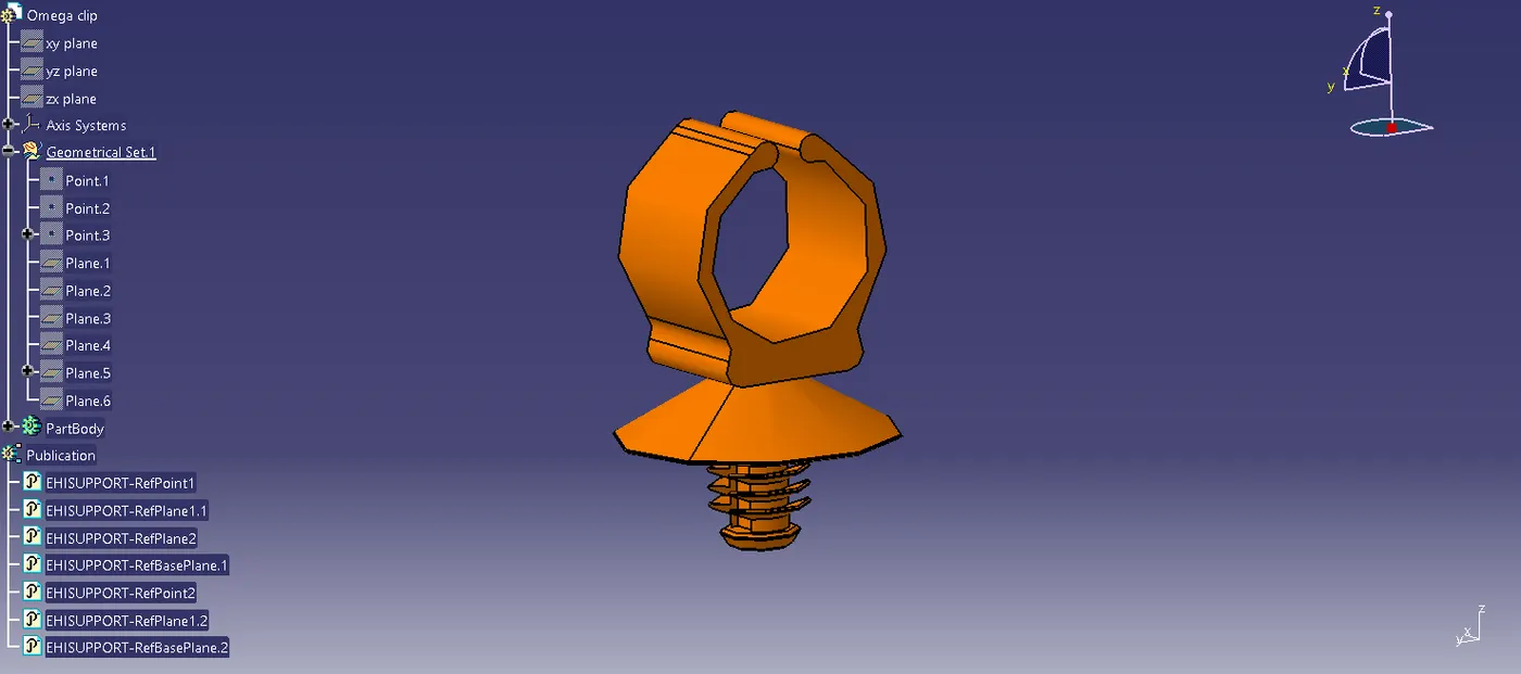
Fig:6
- The Omega clip is defined as a support in electrical part design workbench. The entry,exit planes and points also the base plane are defined. Four omega clips are used in back door harness assembly.
STEP 3: ASSEMBLY OF ELECTRICAL DEVICES IN BACK DOOR:
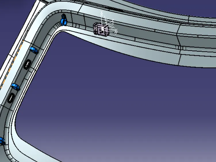
Fig : 7
- All the electrical devices are assembled in the back door appropriately using the mechanical assembly design workbench.
- The above fig.7 shows that the interconnection connector is placed in the back door.
- So there are total 6 connectors used, which are added in the Assembly Engine Harness Geometrical Bundle.
- The tools like manipulation along with compass, snap and smart move features are used to locate all the 6 connectors at their desired locations.
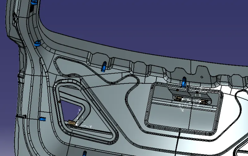
Fig:8
- The above fig.8 shows the connector C-DT06-2S, C-DT06-4S, Omega clips and P-Clamps assembly.
- There are 9 P-clamps and 4 omega clips used in the harness assembly.
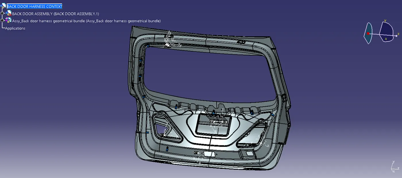
Fig : 9
- The above fig:9 shows that the ‘C-776438’ Which is a 12 Pole connector is used as an interconnection Connector.
- 'C-DT06-4S' which is a 4-pole connector for Tail light and parking sensor.
- 'C-DT06-2S' which is a 2-pole connector for Number Plate Light.
- The connector, clips and clamps are all mounted and asssembled in back door.
STEP 4 : WIRING HARNESS ROUTING AND PACKAGING:
HARNESS ROUTING:
Harness routing basically shows the path of wiring harness into the vechicle. This is representation of the layout of the wiring harness on the vechicle in geometrical way.
HARNESS PACKAGING:
Harness packaging involves the decisions of harness mountings (use of brackets,channels,guiding devices).It also deals with the clearance management,aesthetic management,thermal management,manufacturability,etc..
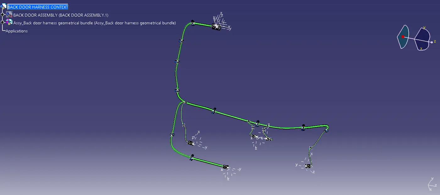
Fig: 10
- The assembled electrical devices are routed in Electrical Harness Assembly workbench. There created geometrical bundle, by defining the geomtrical bundle a new multi branchable product is formed, from there the harness routing process is done.
- Used diamters for routing are 10mm,5mm.
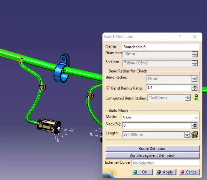
Fig: 11
- The above fig.11 shows that the branch definition for creating routing. Ensure that the routing is not distrubed by external surrroundings.
- To maintain from external objects slack is used, recommended slack is between 5 and 10.
- Ensure that the bend radius is set to 1.4 or greater than 1.5 .
- Ensure the routing rules that each branch should be at a distance of 50mm.
- Minimum distance between clips and near branching point should be 25 mm
- Limit the number of branches form the single branching point to be 4.
- Routing should be in one direction, proper routing gives proper flattening.
STEP 5 : APPLYING PROTECTIVE COVERING FOR THE BUNDLES:
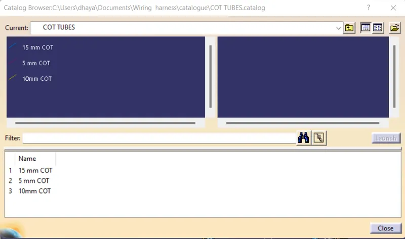
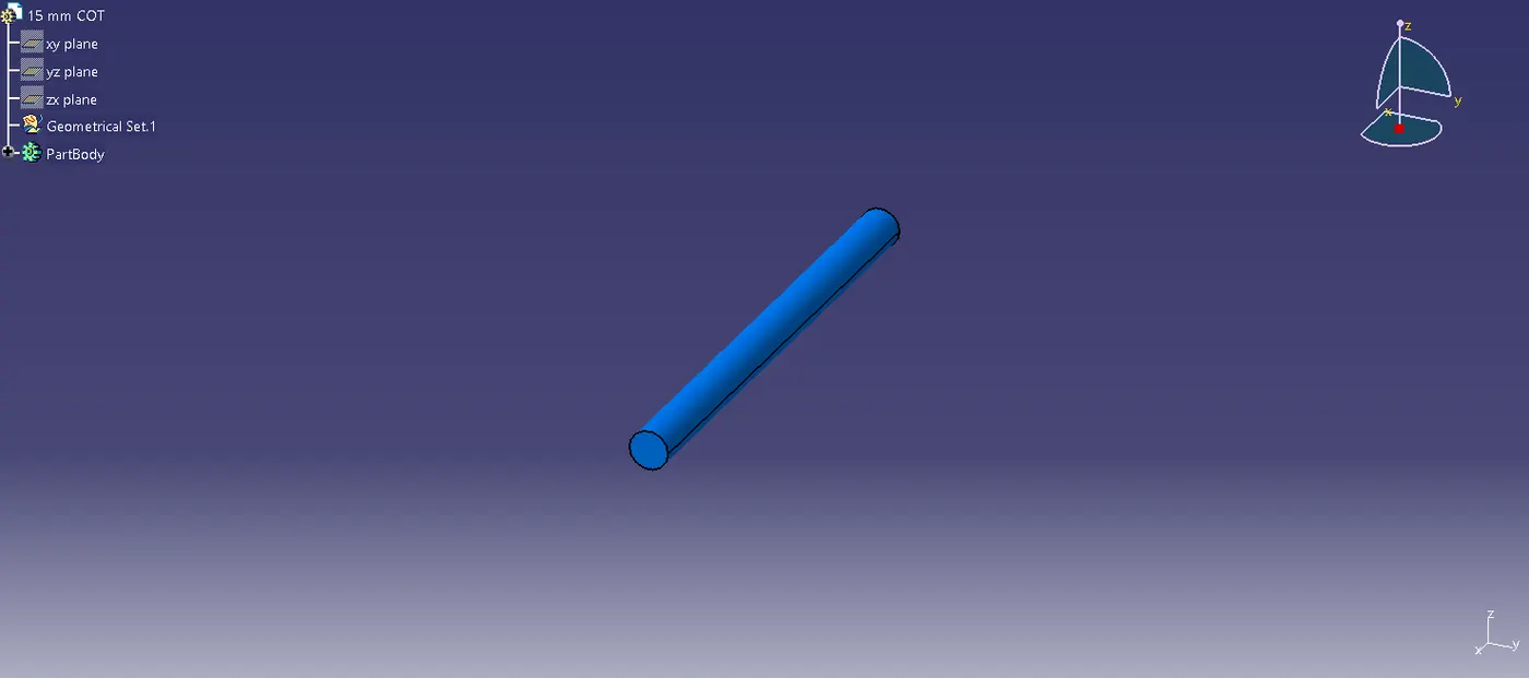
Fig :12
- The above fig.12 shows that the catalogue for protective covering like COT tubes with different diameters.
- The COT tubes helps in protecting the branchables from external elements like heat, accident, human error etc..
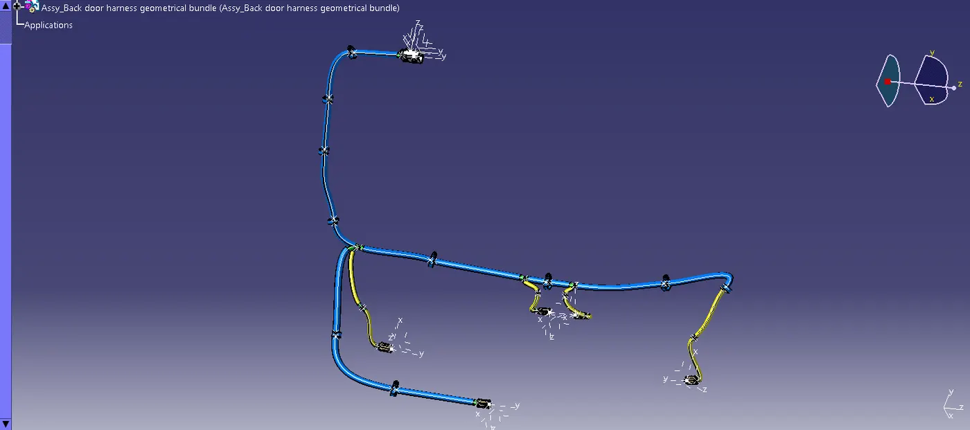
Fig: 13
STEP 6: BUNDLE CONTINUITY CHECKING:
- For bundle continuity check, the steps are;
- Edit<Search<Advanced<Electrical<Bundle segment<Fully connected<Search<True/False.
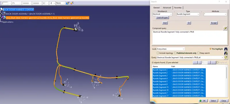
Fig:14
The above fig.14 shows that all the bundles are fully connected so it is ready for flattening process.
STEP 7 : ELECTRICAL HARNESS FLATTENING
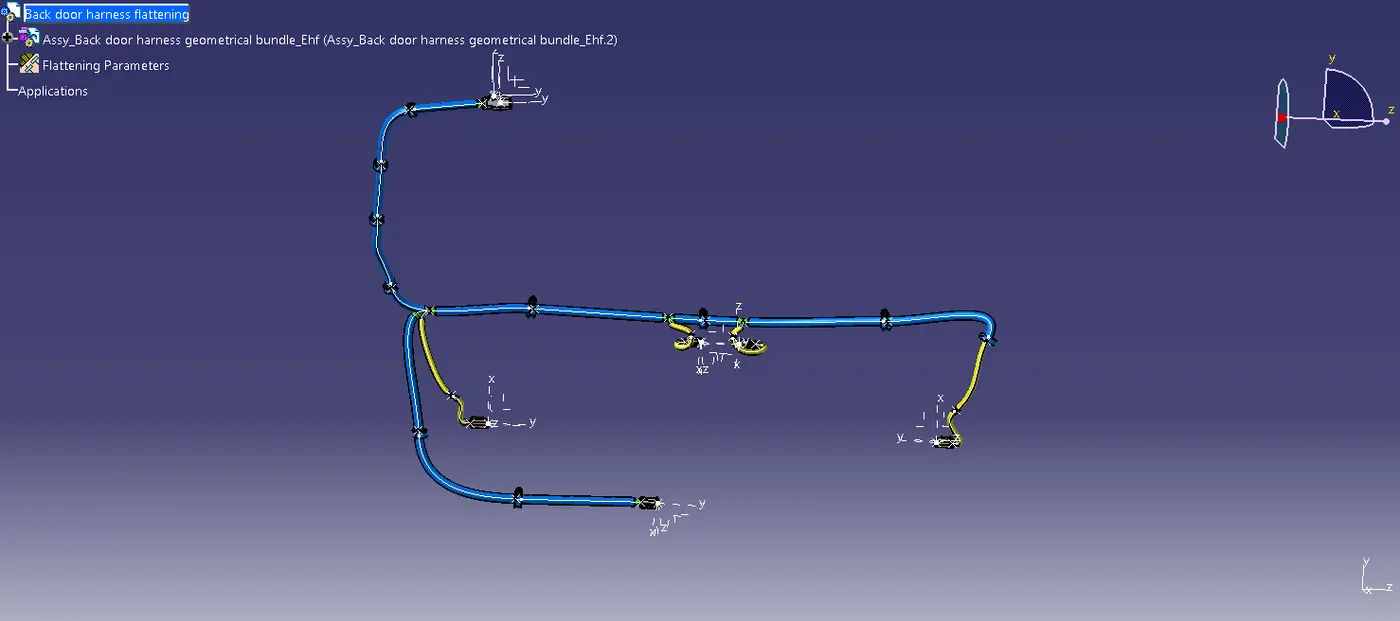
Fig :15
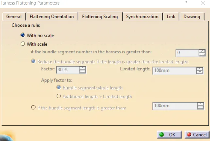
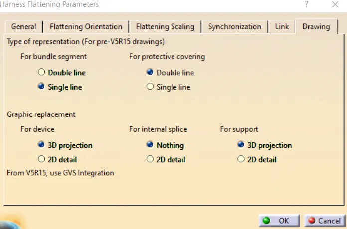
- The above fig.15 shows that the grometrical bundle is extruded into the Electrical Harness flattening with flattening parameters.
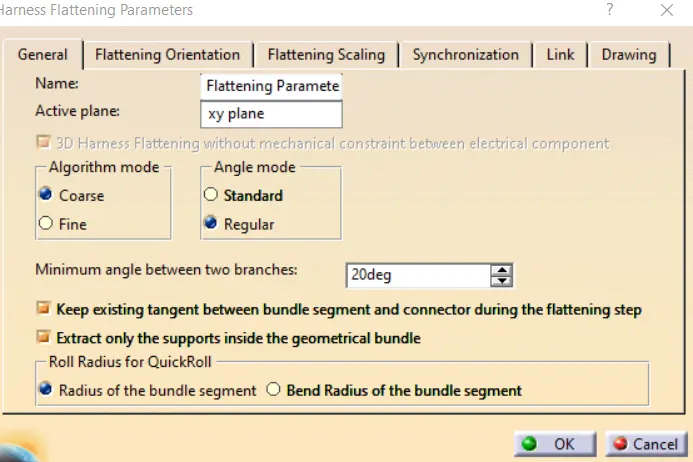
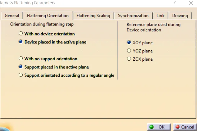
- The flattening parameters and the flatten view are shown below.
FLATTENING PARAMETERS:
FLATTEN VIEW:
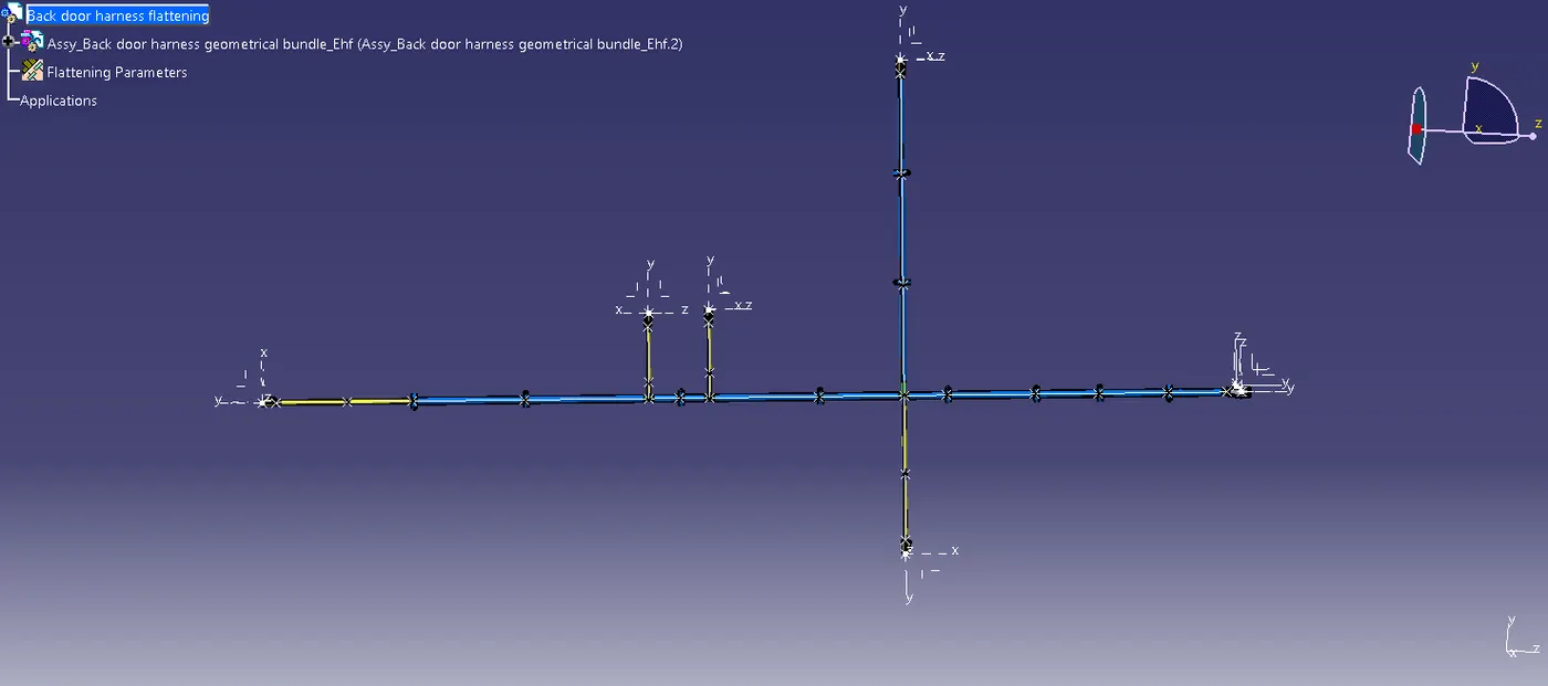
Fig: 16
- The above fig.16 shows the flatten view of the extruded geometrical bundle. By selecting the face of the interconnection connector and selecting all the branches the flatten view is created.
- Here in the flattening work bench the commands like rotate, roll, quick roll are used.
STEP 8 : DRAFTING THE FLATTEN VIEW:
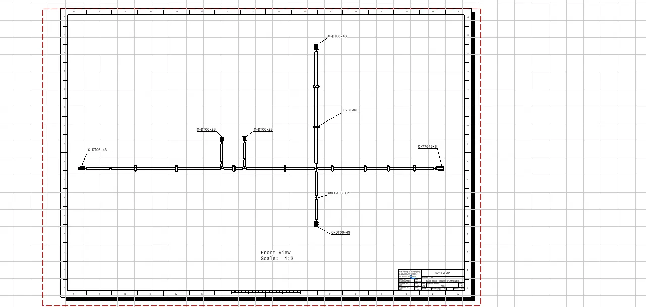
Fig: 17
The flatten view is drafted in the 2D drawing A1 sheet with scale of 1:2 and the parts are addressed.
CONCLUSION:
Hence, the wiring harness for the given Car Back door is routed and the flattened view is drafted using CATIA V5.