Project 2
1) Designing an interleaving DC/DC converter for a data centre application with the following specifications :-
- Input voltage :- 45-60 V
- Output voltage :- 3 V
- Output current :- 100 A
- Efficiency > 85%
- First we need to calculate the required parameter values to design the above converter and the calculations are shown below :-
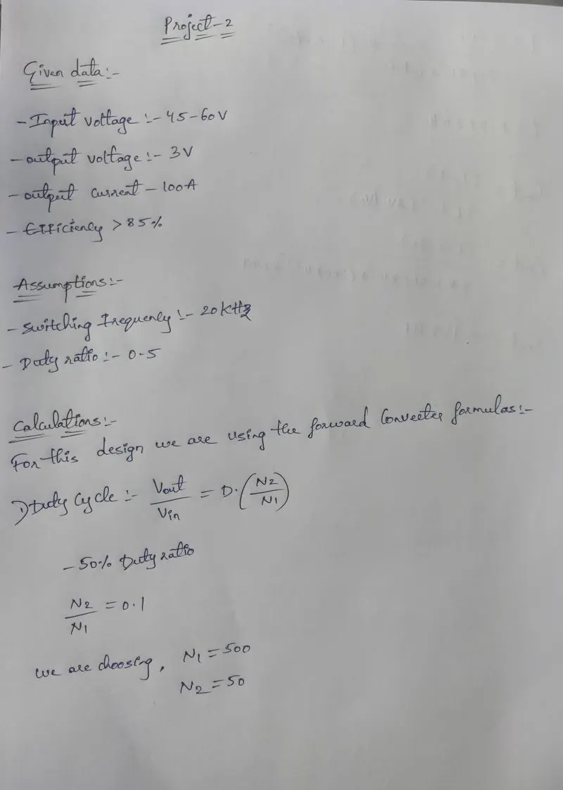
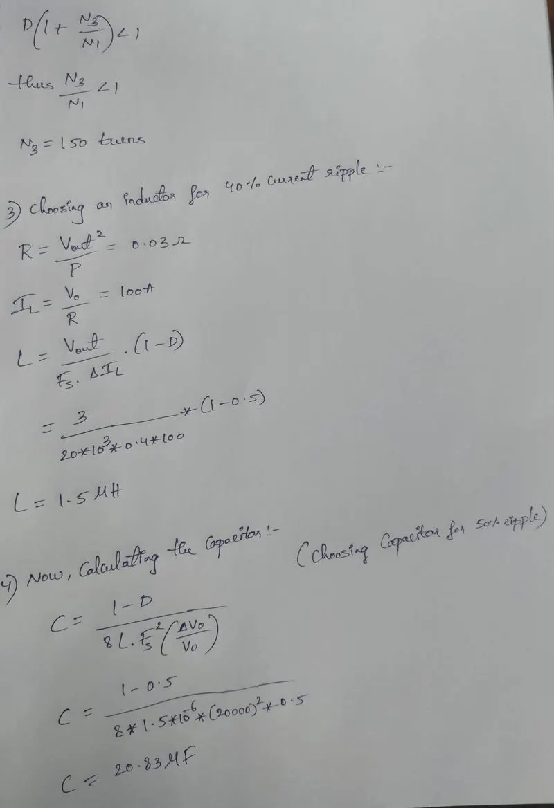
- With the above calculated parameters we design a converter as shown below :-
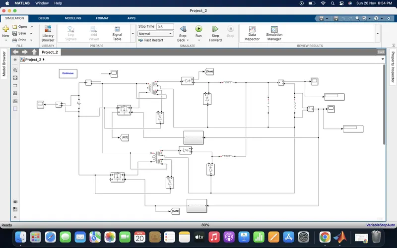
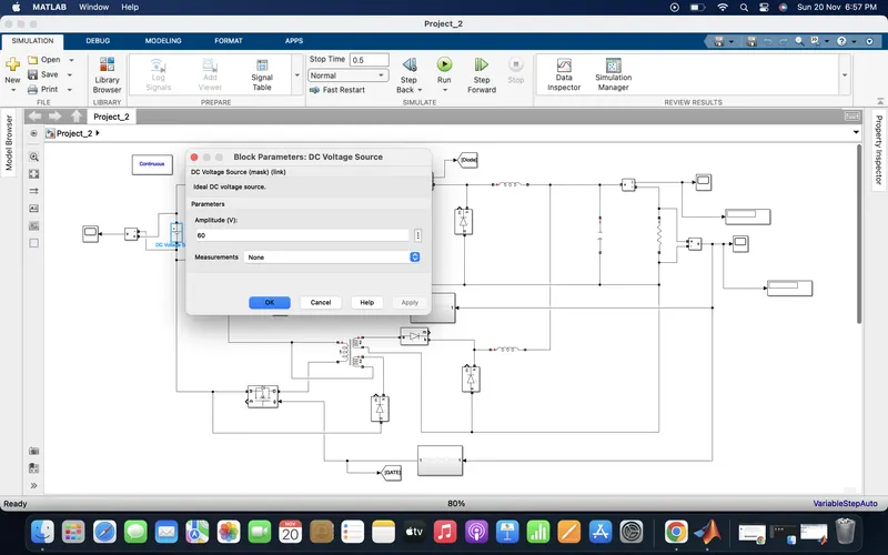
- In the above designed model all the parameter values are shown below :-
1) DC voltage source :-
2) MOSFET :-
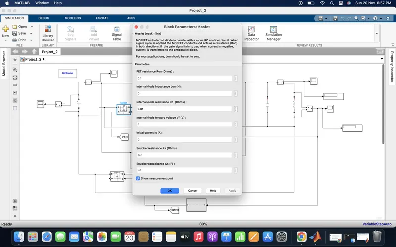
3) Linear transformer :-
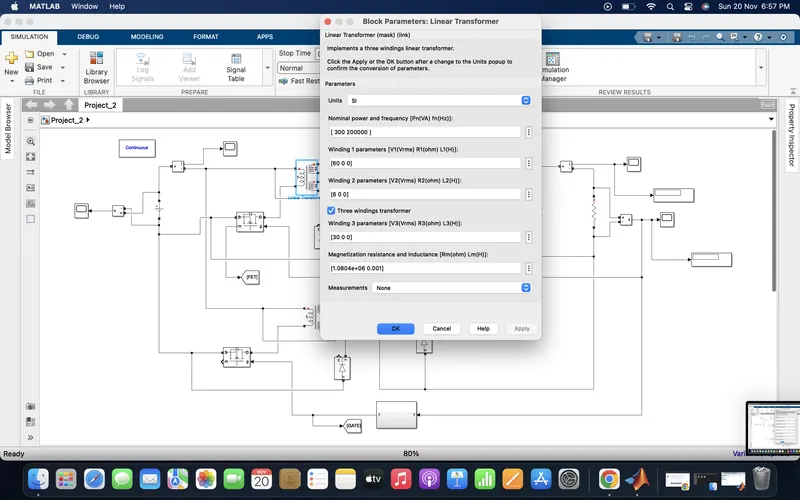
4) Diode :-
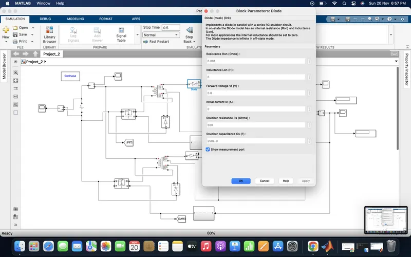
5) Inductor :-
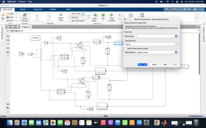
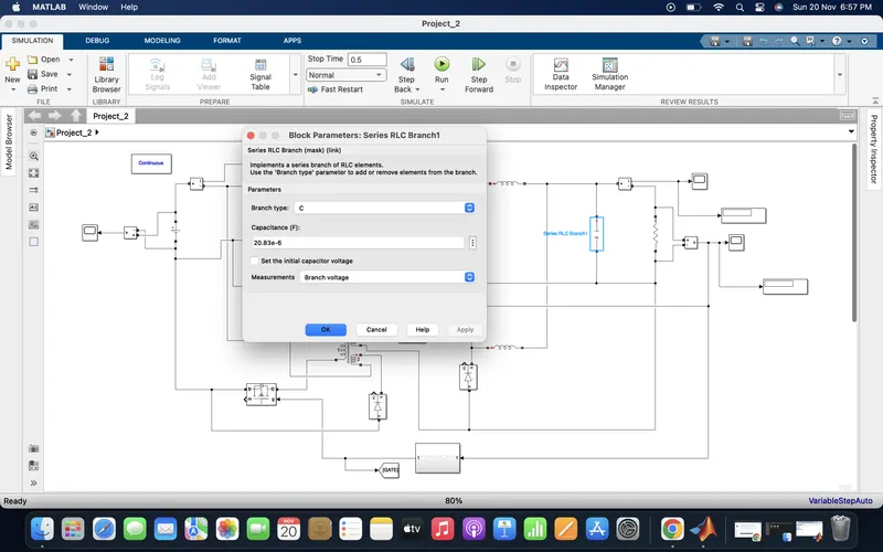
6) Capacitor :-
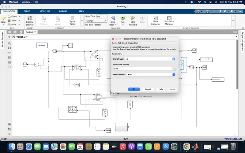
7) Resistor ( Load ) :-
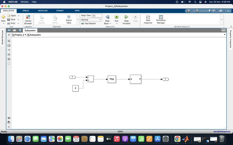
8) Feedback subsystem :-
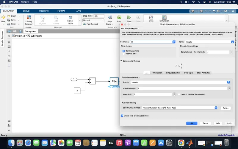
9) PID controller :-
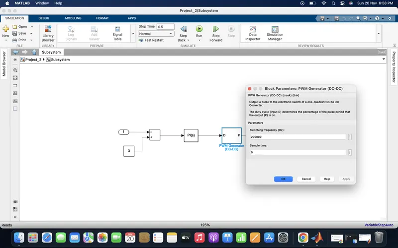
10) PWM generator :-
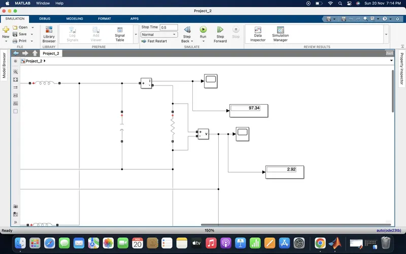
- With the above assigned parameter values the designed simulink model is run for time 0.5 seconds and the results are shown below :-
-From the below image we can see that in display we are getting output voltage of 2.92 V and output current of 97.34 A.
-Input voltage :-

- Then output power = 2.92*97.34 = 284.2328 watts.
- Given input power = 300 watts
- Efficiency = output/input * 100
= 284.2328/300 * 100
- Efficiency = 94.74 %
- We are getting efficiency > 90 % , hence we are getting more efficiency than given in the question.
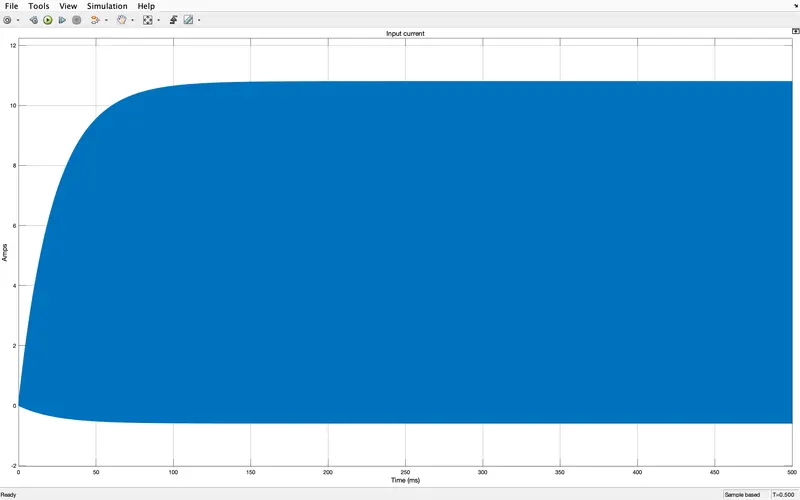
- Input current waveform is shown below :-
- Zoomed out :-
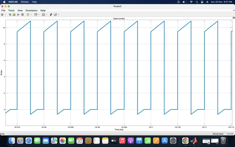
- Zoomed in :- we can see that we are getting a peak input current of 10 A, so the average input current is 5 A.
- Output current :-
- Zoomed out :-
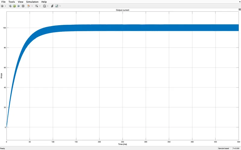
- Zoomed in :-
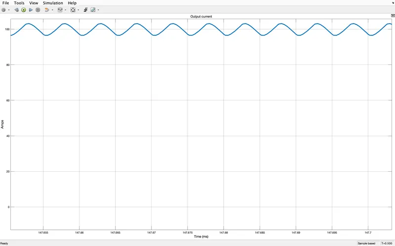
- Output voltage :-
- Zoomed out :-
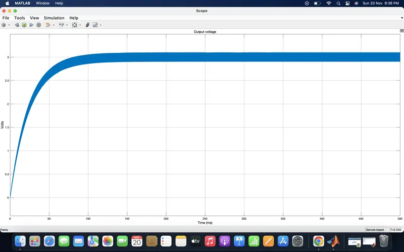
- Zoomed in :-
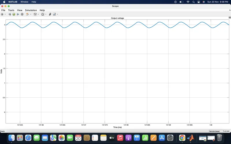
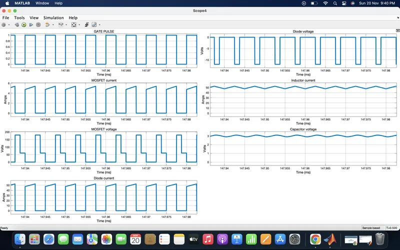
- GATE pulse, MOSFET, Diode, Inductor current, capacitor voltage waveforms are shown below :-
- Summary :-
Interleaved DC-DC step down converter :-
- Interleaving, also called multi-phasing, is a technique that is useful for reducing the size of filter components. This is equivalent to a parallel combination of two sets of switches, diodes, and inductors connected to a common filter capacitor and load. The switches are operated 180 degree out of phase producing inductor currents that are also 180 degree out of phase.
-The current entering the capacitor and load resistance is the sum of the inductor currents, which has smaller peak to peak variation and a frequency twice as large as individual inductor currents( i,e, twice the switching frequency ). This results in a smaller peak to peak variation in capacitor current than would be achieved with a single buck converter, requiring less capacitance for the same output ripple voltage.
-The variation in current coming from the source is also reduced. Thus the input and output ripples of the paralleled (interleaved) buck converter is always less than individual converter.
- The output voltage is obtained by taking kirchoffs voltage law around either path containing the voltage source, a switch, an inductor, and the output voltage.
- The voltage across the inductor is Vs-Vo with the switch closed and is -Vo with the switch open, these are the same as for the simple buck converter where output voltage Vo = VsD.
- Where D is the duty ratio of each switch.
- Each inductor supplies one half of the load current and output power, so the average inductor current is one half of what it would be for a single buck converter. At steady state, the sum of inductor currents( iL1+iL2) supplies the capacitor charging current as well as the average load current.
- Interleaving can be done with other converters as well. However, under some special operating condition, nearly zero output ripple can be achieved, but this happens with 50% duty (D) and in open loop configuration.
- Because in closed loop, the controller automatically adjusts the duty cycle to compensate for the fluctuations of input, load etc.
- Conclusion :-
- Hence to design an interleaving DC/DC converter for a data centre application with the given specifications has been designed, simulated and all the neccessary waveforms are shown successfully.