Project 2
1. Design a Warehouse Building located in Chennai using STAAD Pro Connect Edition. The specification must be as follows:
Width | 30m |
Length | 50m |
Eave Height | 9m |
Bay spacing | 6m |
Soil type | Medium |
Safe Bearing Capacity | 200 kN/m2 |
Roof slope | 1 in 12 |
Assume suitable sections for structural elements. Follow IS800:2007, IS1893 and IS 875
- Prepare a Design Basis Report for the project
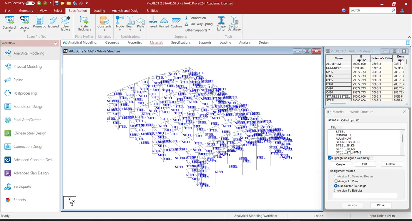
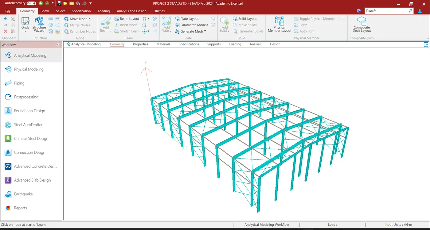
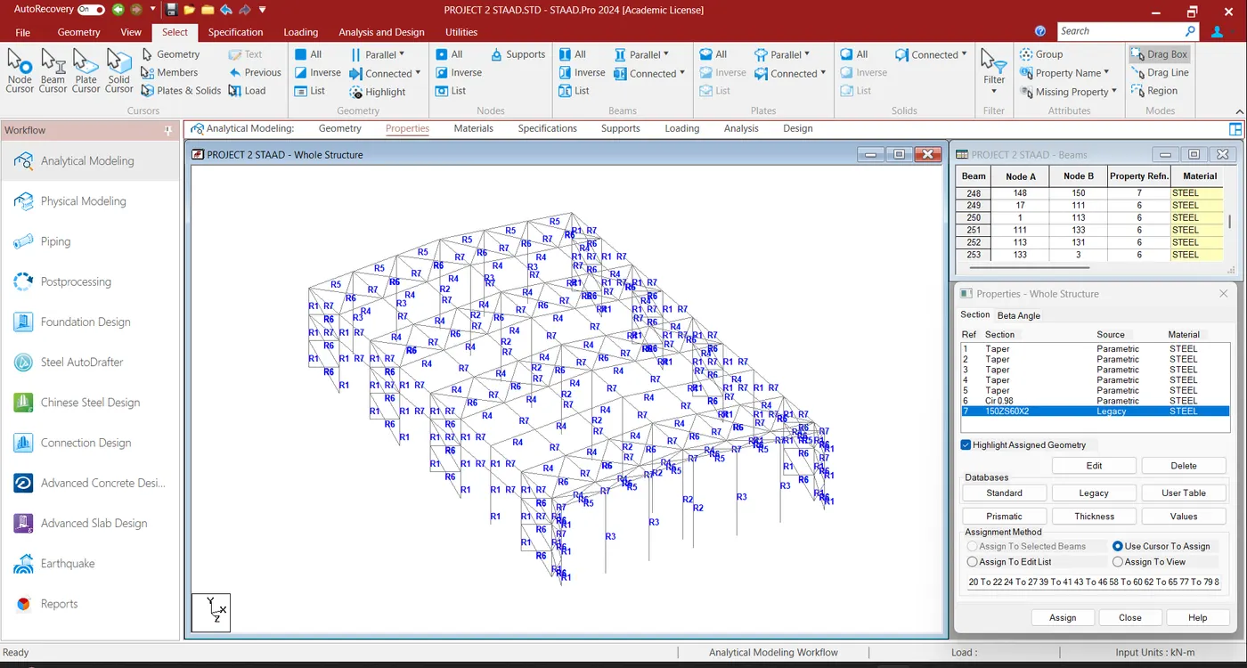
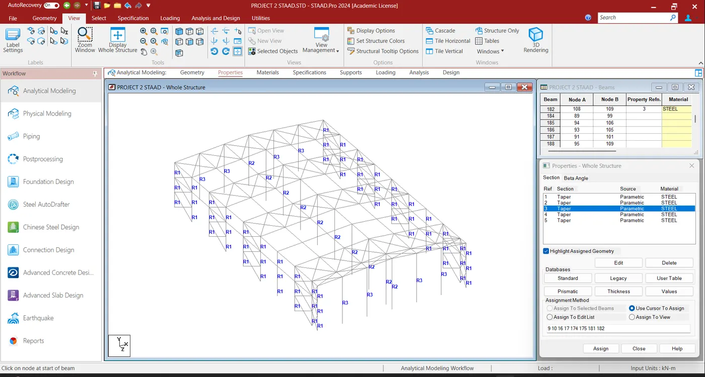
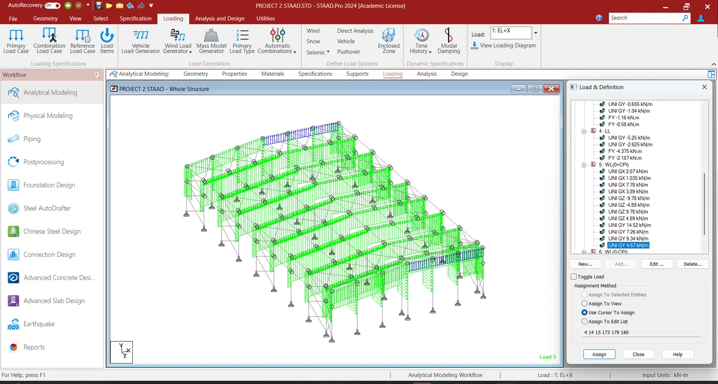
- Create structural model using STAAD Pro Connect Edition
- Prepare DL, LL, WL and EQL load calculations as per IS 875 standards
- Design using MS – Excel
- Steel column
- Rafter
- Base plate
- Pedestal
- Z- purlin
- Design Foundations using STAAD Foundation.
- Attach necessary sketches and drawings wherever required.
- All stipulations, assumptions and design parameter must adhere to Indian Standards.
Solution:
Design Basis Report for Warehouse Building in Chennai
1. Project Details
- Project Name: Warehouse Building
- Location: Chennai
- Purpose: Storage/Industrial Use
- Codes and Standards:
- IS 800:2007 (General Construction in Steel)
- IS 875: Part 1, 2, and 3 (Dead, Live, and Wind Loads)
- IS 1893:2016 (Seismic Design)
- IS 456:2000 (Reinforced Concrete Design)
2. Geometric Details
- Length: 50 m
- Width: 30 m
- Height (Eave): 9 m
- Roof Slope: 1 in 12
- Bay Spacing: 6 m
3. Structural System
- Primary Structure: Steel portal frame
- Secondary Members: Z-Purlins
- Connections: Welded and bolted connections
- Foundation: Isolated footing with pedestal
4. Material Specifications
- Steel Grade: Fe 345 (for structural members)
- Concrete Grade: M30
- Reinforcement: HYSD Fe 500
5. Loading Considerations
Dead Load (DL)
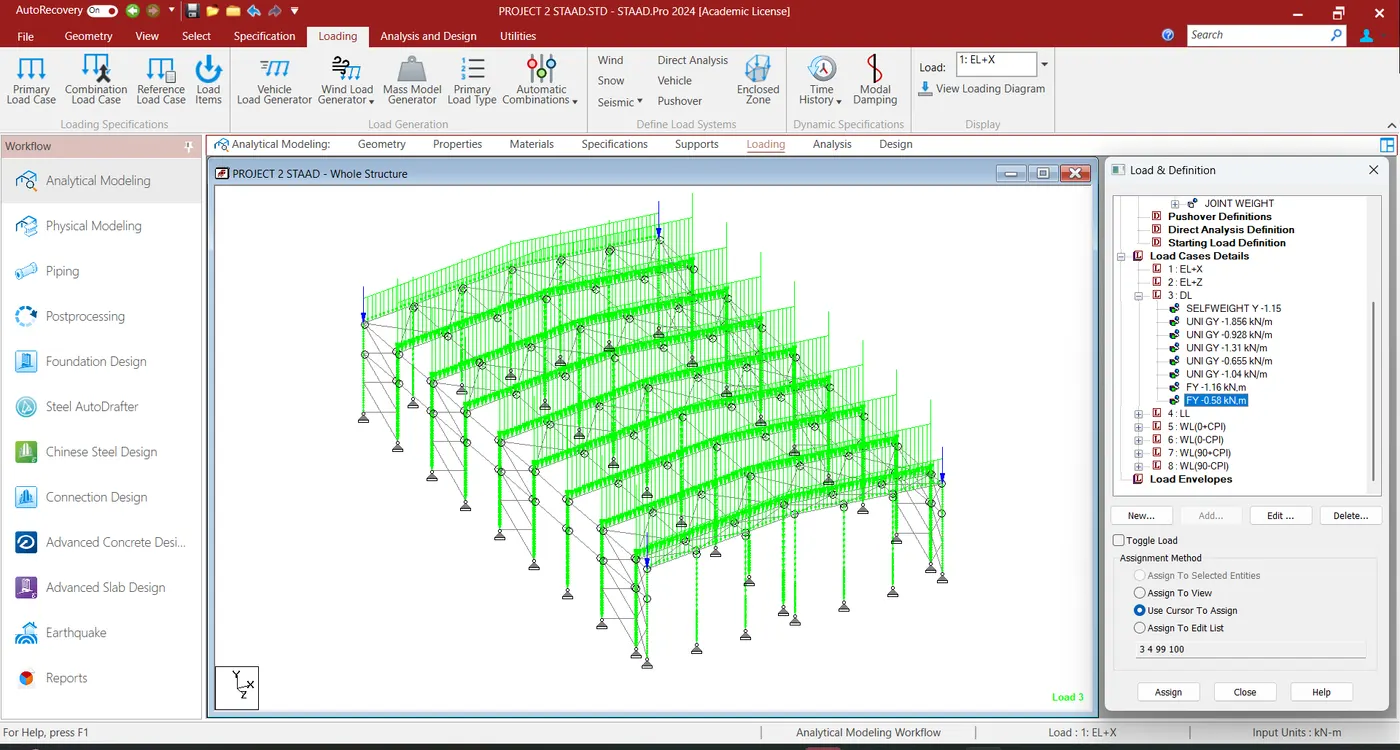
- Self-weight of steel frame (calculated in STAAD Pro).
- Roof sheeting: 0.5 mm thick GI sheeting.
- Unit weight of sheeting = 10 kg/m² = 0.1 kN/m².
- Additional dead loads (insulation, services, etc.): 0.2 kN/m².
Live Load (LL)
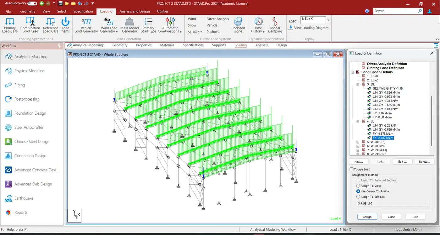
- As per IS 875 Part 2: Live load on roof = 0.75 kN/m².
Wind Load (WL)
- Basic wind speed for Chennai = 50 m/s (IS 875 Part 3).
- Wind pressure coefficient (§Cp§) as per roof slope.
Seismic Load (EQL)
- Zone factor (Z) for Chennai: 0.16 (Zone III).
- Soil type: Medium.
- Importance factor (I): 1.0.
- Response reduction factor (R): 5 (Steel Frames).
- Base shear calculation: As per IS 1893.
6. Soil Data
- Soil Type: Medium soil
- Safe Bearing Capacity (SBC): 200 kN/m²
7. Design Software and Tools
- Structural Analysis: STAAD Pro Connect Edition
- Foundation Design: STAAD Foundation Advanced
- Member Design: MS Excel
8. Design Procedure and Calculations
Step 1: Structural Modeling in STAAD Pro
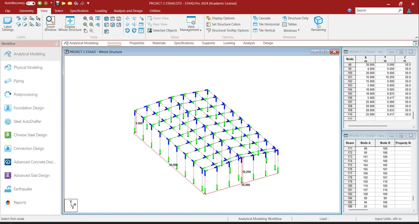
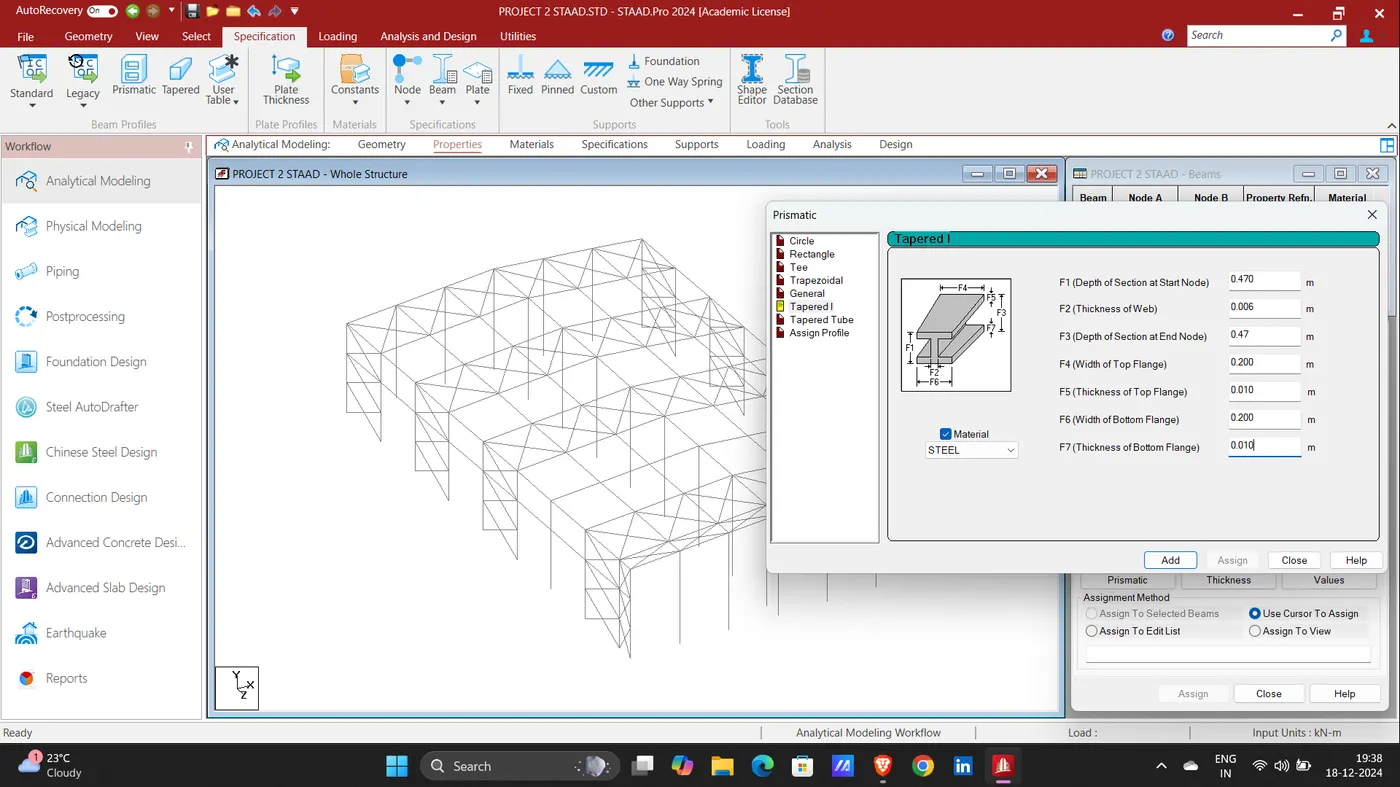
- Geometry Definition: Define the structure with dimensions: 50m x 30m with an eave height of 9m.
- Material Properties: Assign Fe 345 steel for members and M30 concrete for foundations.
- Section Properties: Assign appropriate IS sections (e.g., ISHB for columns, I-sections for rafters).
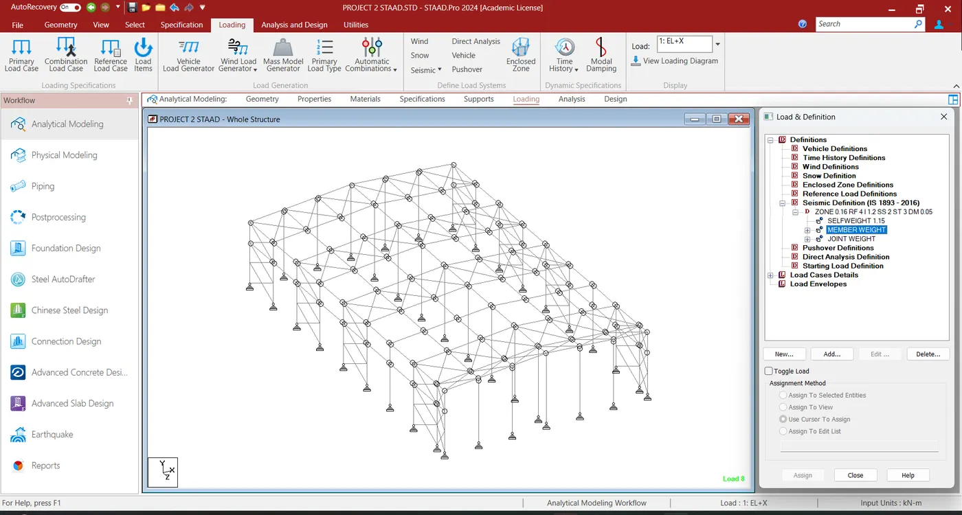
- Load Application:
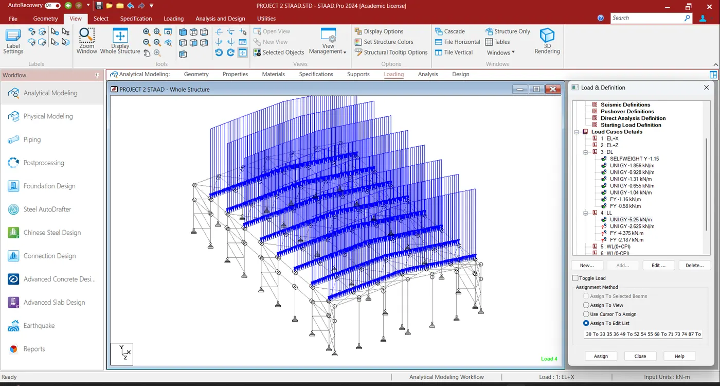
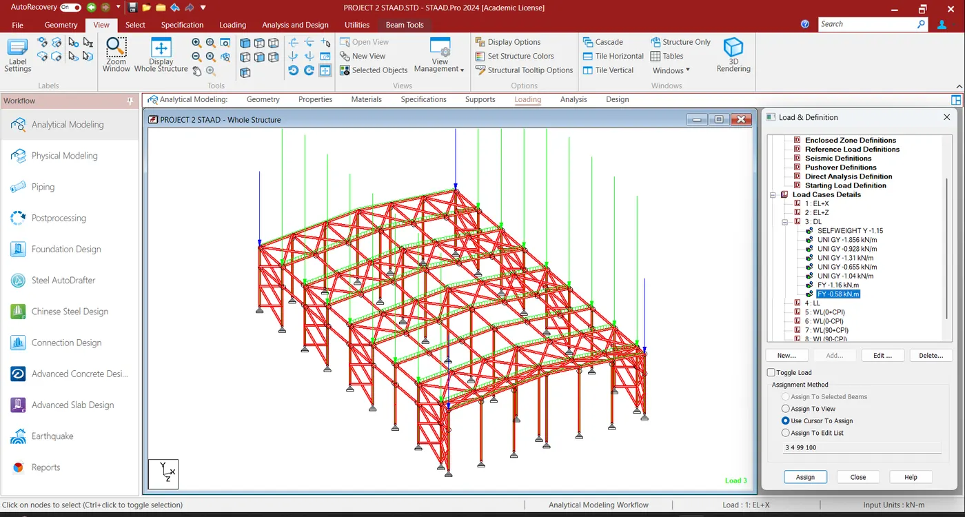
- Dead Load: Include self-weight and additional permanent loads.
- Live Load: Apply roof live loads per IS 875 Part 2.
- Wind Load: Apply wind pressures based on IS 875 Part 3.
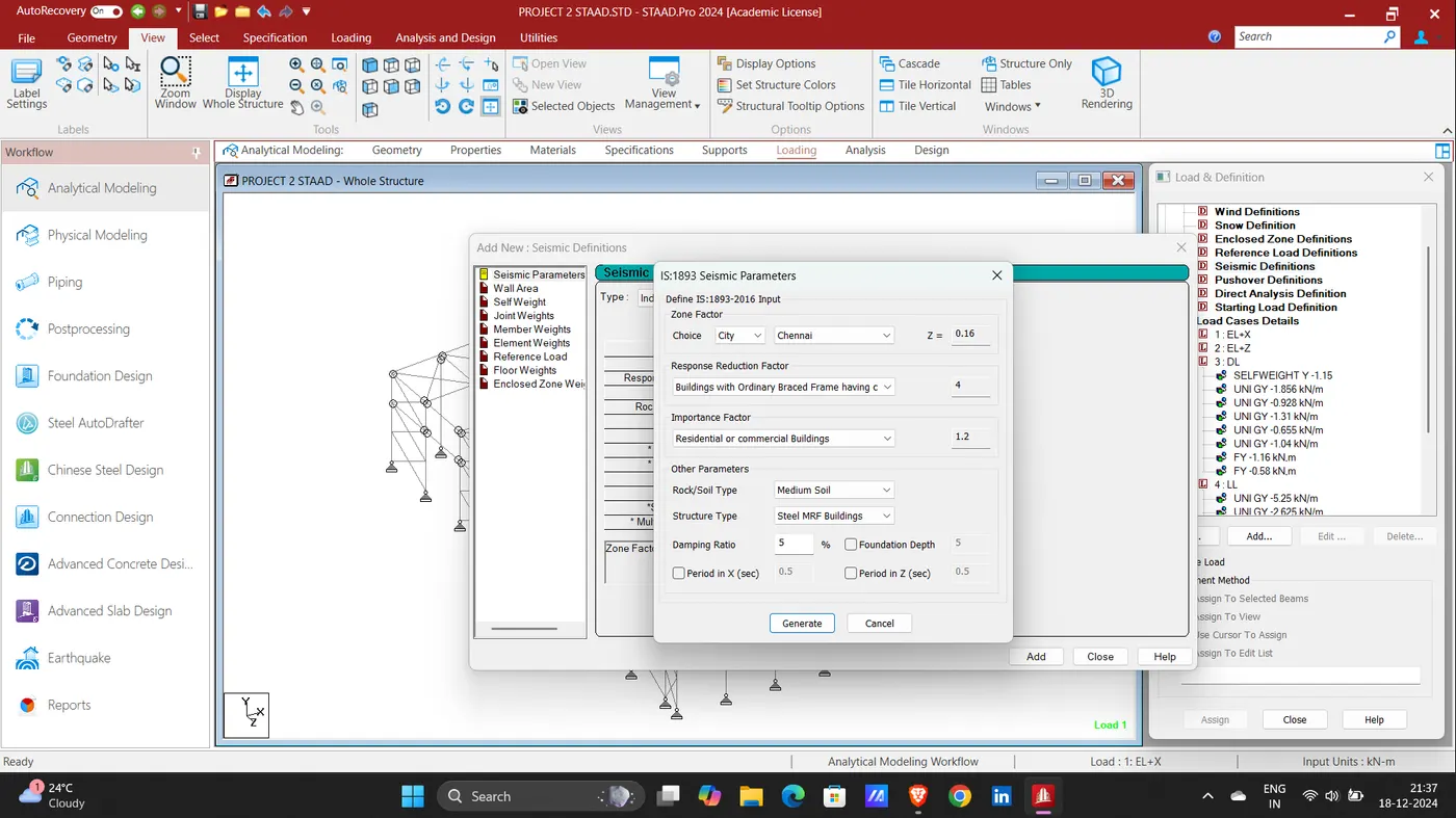
- Seismic Load: Define seismic parameters as per IS 1893.
- Analysis: Perform the analysis to extract member forces, moments, and support reactions.
Step 2: Dead Load Calculation (DL)
- Self-weight of members: Auto-calculated in STAAD Pro.
- Roof sheeting: Calculate dead load based on unit weight = 0.1 kN/m².
- Insulation and services: Add additional load of 0.2 kN/m² uniformly distributed.
Step 3: Live Load Calculation (LL)
- Apply uniformly distributed live load of 0.75 kN/m² on the roof.
Step 4: Wind Load Calculation (WL)
- Determine design wind speed (Vz) based on basic wind speed (Vb) = 50 m/s.
- Calculate design wind pressure:
- Apply pressure coefficients based on the roof slope (1 in 12) and shape of the structure.
- Distribute wind loads on the structure using STAAD Pro.
Step 5: Seismic Load Calculation (EQL)
- Compute the horizontal seismic coefficient (Ah): where:
- Z = Zone factor (0.16 for Zone III).
- I = Importance factor (1.0).
- Sa = Spectral acceleration (based on soil type).
- R = Response reduction factor (5 for steel frames).
- Apply lateral seismic loads on the structure.
Step 6: Member Design Using Excel
- Steel Column Design:
- Choose ISHB or built-up sections.
- Check axial load, biaxial bending, and slenderness ratio as per IS 800:2007.
- Rafter Design:
- Analyze for bending moment and axial force.
- Verify deflection limits.
- Z-Purlin Design:
- Calculate bending moment, shear force, and deflection under DL + LL.
- Base Plate Design:
- Determine bearing pressure and thickness of the base plate.
- Pedestal Design:
- Design for combined axial load and bending moment.
Step 7: Foundation Design Using STAAD Foundation Advanced
- Import reactions from STAAD Pro.
- Assign soil properties (SBC = 200 kN/m²).
- Design isolated footings to resist applied loads and moments.
- Check stability against overturning and sliding.
9. Structural Model in STAAD Pro
- Create 2D and 3D models of the portal frame.
- Analyze the structure for all applied loads.
- Extract results for member forces, moments, and reactions.
10. Outputs and Drawings
- Generate 2D drawings for:
- Column-beam connections.
- Base plate details.
- Z-purlin layout.
- Footing reinforcement.
- Create 3D views of the structural model for visualization and validation.
2. Design a simply supported gantry girder to carry electric overhead travelling crane
Given:
Span of gantry girder = 7 m
Span of crane girder = 9 m
Crane capacity = 250 kN
Self-weight of trolley, hook, electric motor etc. = 40 kN
Self-weight of crane girder excluding trolley = 100 kN
Minimum hook approach = 1.0 m
Distance between wheels = 3 m
Self-weight of rails = 0.2 kN/m
1. Input Data and Assumptions:
Given:
- Span of gantry girder = 7 m
- Span of crane girder = 9 m
- Crane capacity = 250 kN
- Self-weight of trolley, hook, electric motor, etc. = 40 kN
- Self-weight of crane girder excluding trolley = 100 kN
- Minimum hook approach = 1.0 m
- Distance between wheels = 3 m
- Self-weight of rails = 0.2 kN/m
2. Loads Acting on Gantry Girder:
The gantry girder is subjected to various loads, which include:
- Dead Load (DL) - This includes the self-weight of the gantry girder, crane rails, crane girder, and other components.
- Live Load (LL) - This includes the live load, which consists of the crane capacity (dead load of the crane, hook, and trolley), and other dynamic loads such as the operating load and impact factors.
a) Dead Load:
- Self-weight of gantry girder = Consider the section and material for the gantry girder and estimate the self-weight based on dimensions.
- Self-weight of rails: 0.2kN/m×9m=1.8kN.
- Self-weight of crane girder = 100 kN (excluding trolley).
b) Live Load:
- Crane load (capacity) = 250 kN.
- Trolley and hook load = 40 kN.
- Dynamic load due to crane motion: This can be considered using an impact factor (usually 1.25 for EOT cranes). So, the total crane load (dynamic) is: Total Crane Load=250kN+40kN=290kN Multiply by the impact factor (1.25): Live Load=290kN×1.25=362.5kN
3. Load Distribution:
For a simple gantry girder:
- Crane load is applied at the location of the wheels (distance between wheels = 3 m). The total load of 362.5 kN is distributed across the two wheel positions.
For a uniformly distributed load due to the crane, calculate:
w=SpanTotal Load=9362.5=40.28kN/m
4. Structural Design Using STAAD Pro:
Procedure for Modeling in STAAD Pro:
- Open STAAD Pro and create a new model.
- Modeling the Gantry Girder:
- Define the material properties (e.g., steel with a typical grade like IS 2062 or similar).
- Define the cross-section of the gantry girder (e.g., I-beam, box girder).
- Create Geometry:
- Input the span (7 m) for the gantry girder.
- Define the geometry of the crane girder as a beam structure with the span of 9 m.
- Ensure that the crane girder is placed on the gantry girder with proper supports.
- Apply Loads:
- Apply a uniform load for the self-weight of the girder (based on the calculated self-weight).
- Apply the crane loads as concentrated loads or uniformly distributed loads at the appropriate positions.
- Apply the load due to the rails and other components as needed.
- Define Supports:
- Define simply supported boundary conditions (rollers or pinned supports) for the gantry girder at both ends.
- Run Analysis:
- Perform a linear static analysis to determine the bending moments, shear forces, and deflections.
- Design the Sections:
- Use the results from the analysis to size the sections for bending, shear, and deflection criteria.
- Check the stress levels against allowable values (based on the material strength).
Example of Load Application in STAAD Pro:
- Apply the dead load for the self-weight of the girder and the crane girder.
- Apply the live load due to the crane, which is assumed to be a distributed load along the girder length.
- Apply concentrated loads at the wheel positions (3 m apart), simulating the crane's weight.
- Apply dynamic impact factors to account for crane movement.
5. Design Check:
Once the loads are applied and the analysis is complete, perform the design checks for:
- Bending Moment: Ensure the maximum bending moment is within allowable limits based on the material and section chosen.
- Shear: Verify that the shear stress is safe.
- Deflection: Check for deflections, ensuring they do not exceed allowable limits.
- Crane Hook and Trolley Support Design: Ensure the gantry girder can safely support the hook and trolley loads.
6. Final Section Selection:
After the analysis in STAAD Pro, the program will output the maximum bending moment, shear forces, and deflections. Based on these results:
- Choose the cross-section of the gantry girder (e.g., I-beam, box section) based on strength and serviceability requirements.
- Perform additional checks such as for stability, fatigue (if needed), and other relevant factors.