Project 2
- The SOC of the battery at 2 *104second of the battery operation
answer :
blocks used :
1) Battery :
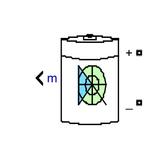
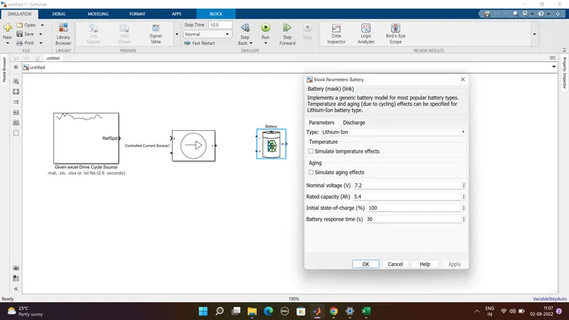
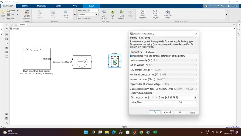
- Here the battery block can be found in the director of electrical/specialized power systems/electrical drives/extra sources
- Here we used default values of the Li-ion battery.
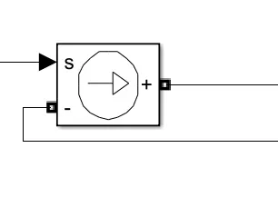
2) Controlled voltage source:
3) Bus selector
4 Dri 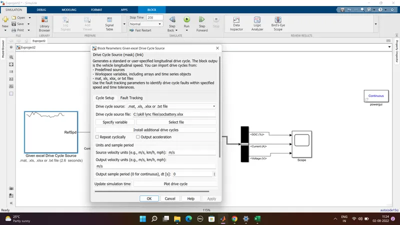
Drive cycle input plot:
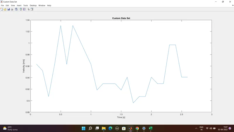
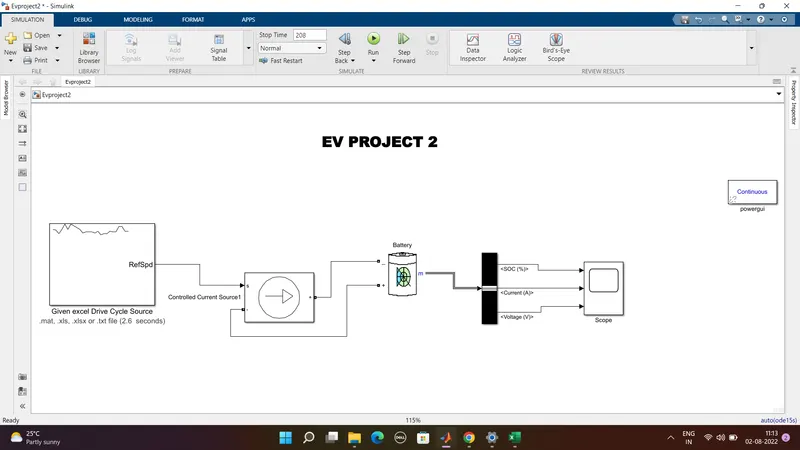
- This current cycle is given as the input to the model through the drive cycle input block i.e excel file wich is given in the question
- Here the drive cycle stop time is 2*104 i.e 208sec
- so the simulation run time is 208sec
- Here the output of the drive cycle is given to the current controlled source which is connected to the battery as a load
- so here the battery is dicharged accroding to this siginal given by the data which is excel data input drive cycle data
- Here the power gui block is rquired for any simulation of the simulink model
- It mainly used to store the equivalent simulink circuit which represents the state space model
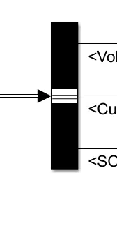
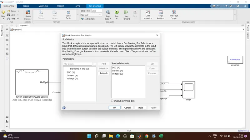
- The ouput of a battery is given to the scope through the bus selector the bus selector outputs the battery siginals to the scope
Output results:
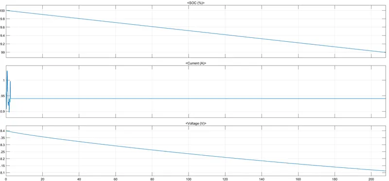
The above graph gives the results of SOC voltage and current
Here we operated the soc of battery at 2*104
And we can also see that how the soc of the battery changes it mainly decreases from the 100 to 99 and voltage aslo dcreses
The maximum heat generation in the battery pack
Max heat generation = Max Joule Heat + Entropy factor
Max Joule Heat = I^2 *R*t
Max Joule Heat =
Joule Heat =
Max heat generation = 0.0006823936 + 2 = 2.0006823936 Jouls
The Max heat generation is 2.0006823936 Jouls