Week - 4
solution 2: Make a Simulink chart for the “Gear shift” logic as per below conditions
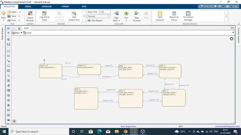
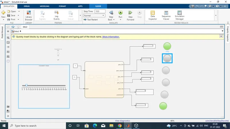
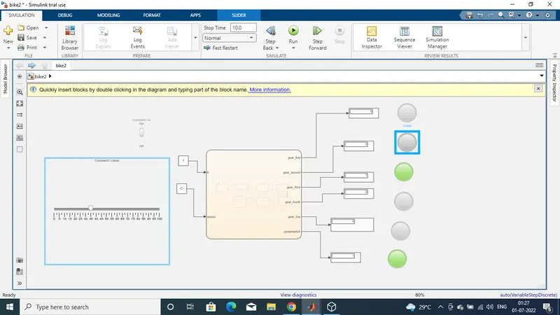
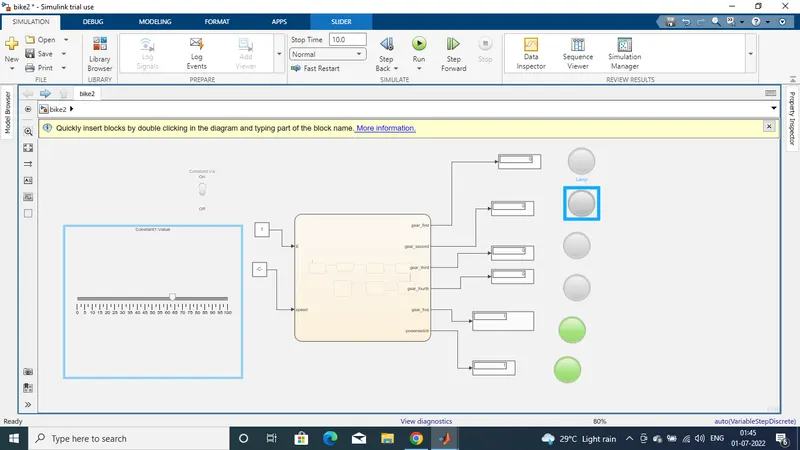
Logic : In this system given speed range is 0-100 so we use slider block for the given input speed . The first gear speed range is 0 to 15 so the entry of state for the 1st gear is 0 < -speed and 15 - speed it is the exit condition of gear in speed greater than 15. In gear 2 entry state is 16 - speed and 25 < -speed the exit condition is between speed 16 to speed 25 Same conditions are applied in all gears and the output is gives from lamp and dispaly block Stateflow Chart :
- Implement control logic of a “washing machine” using Stateflow as per given sequence
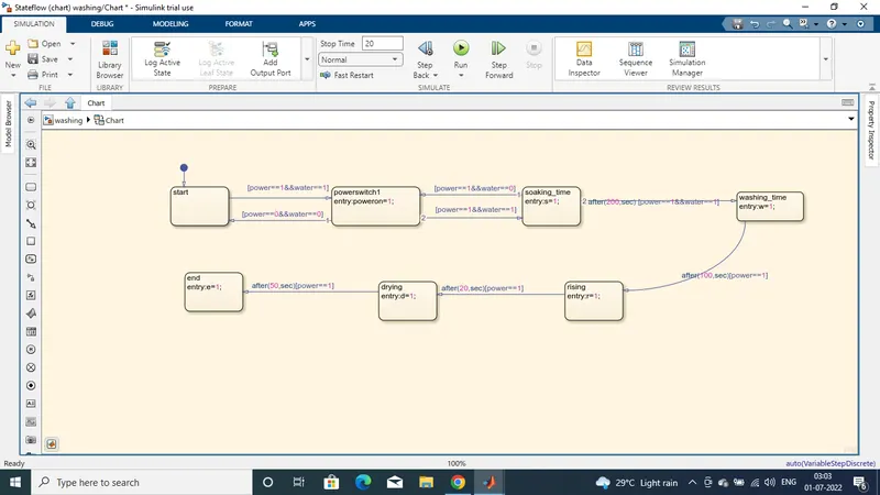
in the above control logic first created two states 1 ] Power -- 1 / Power == 0 its use for activation of supply to system . Power == 1 it means Power on and Power -- 0 it means Power off . 2 ] W == 1 / W = -0 its for to know water is available or not . When both are activate then machine start to process run Then next four states are created for the flow order of the Soaking , Washing , Sinking , Drying with their time of operation for soaking 200 sec , for washing 100 sec , for rinsing 20 sec and for drying 50 sec . Then create exit condition of the state kept as zero at the enter of state then the operation state is zero and when its complete the is one . after all process done then its all shows through Lamp , and then we can shut the machine off
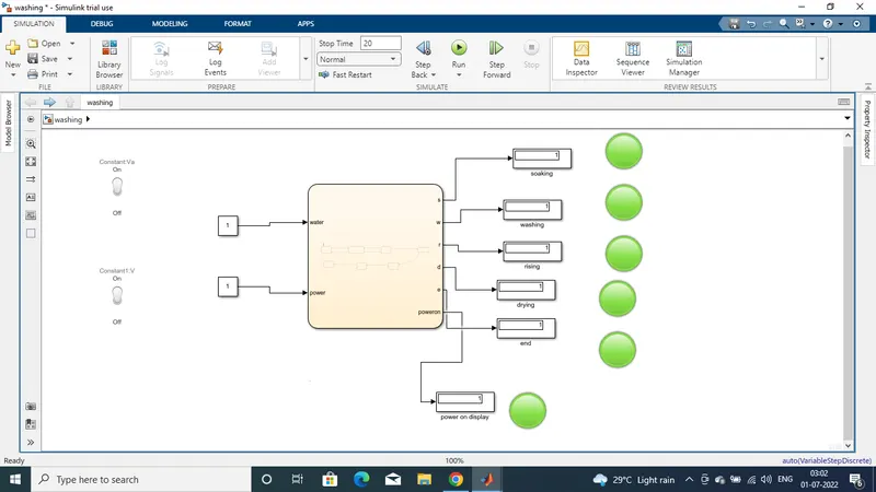
In this model the power and water control switch are on so full system are run and they indicate through lamp . It completes a cycle through as first paking for 200 sec then washing for 100 sec and then the use water goes out from machine new fresh water enter in machine it all shows through lamp indicator then rinsing will be done for 20 s and the drying for 50 sec and then the cycle is end and it also indicate through lamp .