Designing of Tail Lamp for a vehicle
Design and modelling of Tail Lamp for SUV vehicle
AIM
The aim of the project is to build a complete assembly of tail lamp which consists of lens, reflectors, housing, wiring harness and other attachment features on the housing in order to fix the Tail Lamp with the vehicle. Catia V5 is the software used to make the complete design of this project.
INTRODUCTION
Tail Lamp is present at the rear side which basically tells the presence of a vehicle to let the other drivers know the approximate size and shape of the vehicle. It is one of the most important safety factors for a vehicle. The colour of the tail lamp is mostly red as it should be visible clearly to the other drivers. The lens and the housing of the Tail lamp are designed as per the industry standards by checking all the regulations while designing the reflectors and making sure that there is no bleeding of light happening inside the casing of the Tail lamp. Anti-fog condition is also been taken care of so that condensation does not happen inside the reflector region. The bulbs which are used in the lighting industry are taken as input and placed at appropriate position in the reflectors.
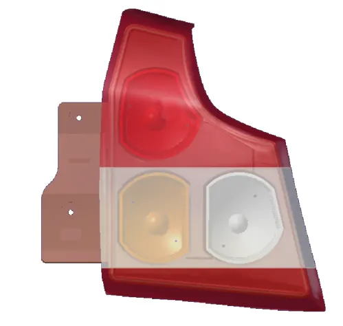
The Tail lamp designed is this project is shown below:
Front view:
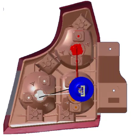
Lens assembly back view:
Lens assembly side view:
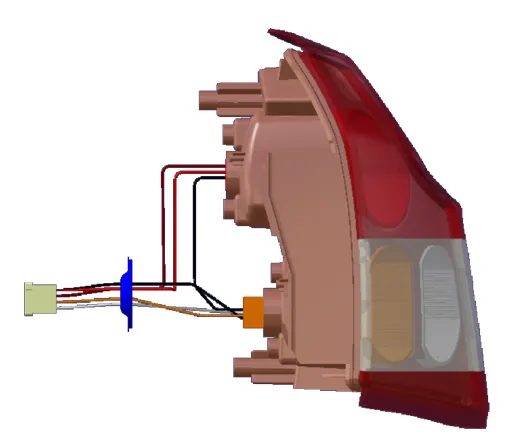
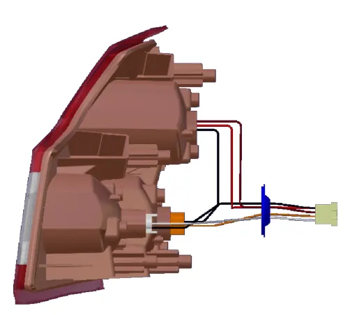
The general position of tail lamp is shown below:
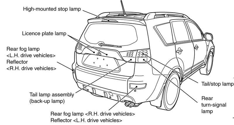
The steps involved in making the Tail lamp assembly are:-
1. Designing the solid body of the lens along with the welding track.
2. Determining the shape and positions of the tail stop, turn and reverse reflector.
3. Designing the solid body of the reflectors.
4. Designing the solid body of the housing for the lens along with welding track for the housing.
5. Make screw bosses for the reflector and the housing.
6. Creation of red and clear lens for the tail lamp.
7. Presenting the final product.
8. Drafting of the assembly of the tail stop lamp.
9. Bill of material.
PROCEDURE:
1. Designing the solid body of the lens.
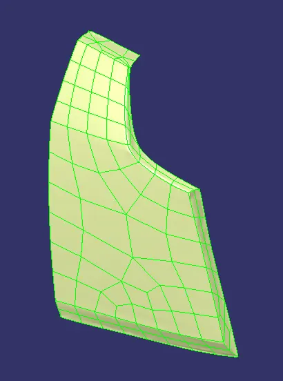
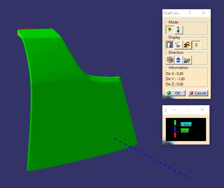
The tooling axis for the input lens was determined and it was checked whether the lens will clear along all direction using the draft analysis feature.
The surfaces of the class A provided was irregular around the edges and the surface quality was also not good, so some modifications had to be done around the edges to work with the class A and rough surface offset feature was used to make the class B surface for the thickness of the lens. The class C surface was also made after making the class B surface and the all the surfaces were closed.
Close surface feature was used to make the solid body of the lens.
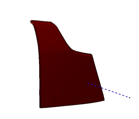
From the draft analysis we can observe that the lens designed can be produced along the tooling direction, which is shown below:
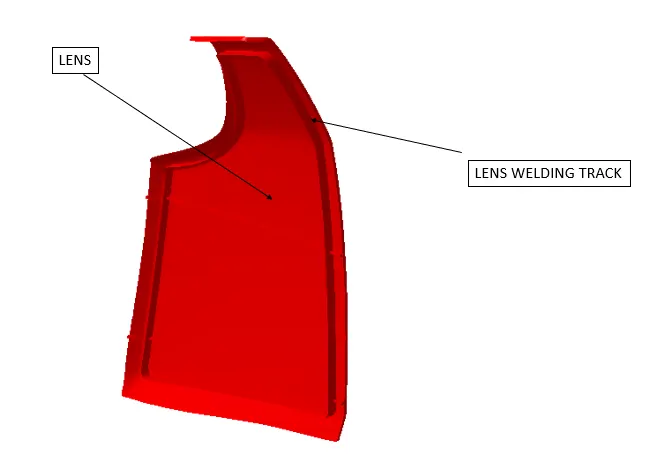
The next step is to design the welding track for the lens, which is then union trimmed with the lens solid body to attach it with this. Below image shows lens along with welding track
2. Designing the reflectors for the lens.
The tail lamp will consist of 3 functions.
1. Tail stop function
2. Turn function.
3. Reverse function.
The tail stop function will glow the red light when required, turn function will be activated when the driver presses the turn direction button and the reverse function will be activated when the vehicle will be moved in reverse direction.
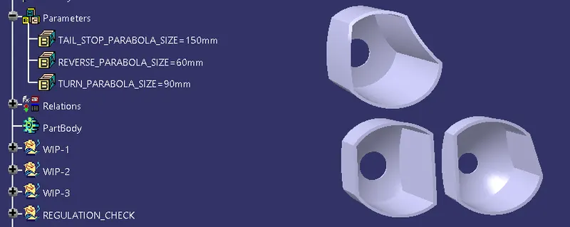
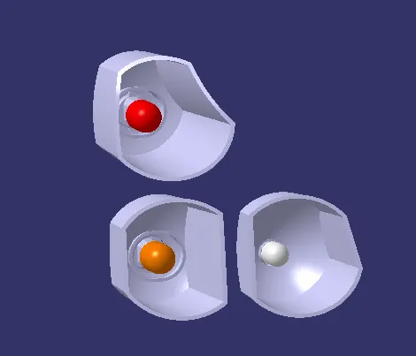
In order to design the reflectors a parabola is first designed for the back side and then circular surface was made by taking focal point as the centre, both of them were split together to get desired shape and position of the reflector. Parameters and relations feature was used to specify the diameter of the parabola so that in future it can altered easily as per requirements by the future industry.
The next step is to place the bulbs at the focal point of the reflector. Bulbs were first imported into the workspace and then translation feature was used to position them at required positions. The bulbs that were used for each functions are mentioned below:
Tail Stop reflector - W21/5W Bulb
Turn reflector - W21W Bulb
Reverse reflector - W16W bulb
Along with the bulb, bulb holder and their seating area were also imported. With the help of bulb holder seating area the reflector was union trimmed so that a circular hollow shape can be made on the reflector for placing the bulb at the focal point position.
Placing the reflectors at the required position in the lamps is the most important step in designing the reflectors. As per industry certain rules are followed which specifies what should be the minimum and maximum distance at which each function should be placed. By considering all these factors the reflectors were positioned at required position following all the industry standards.
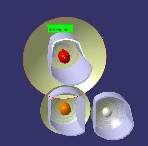
Fig 1
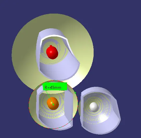
Fig 2
Fig 3
In the above figures 1,2 and 3 the parabolas were designed with a radius of 75 mm for tail stop reflector, 45mm for turn and reverse reflectors as these are the standards followed in the industry.
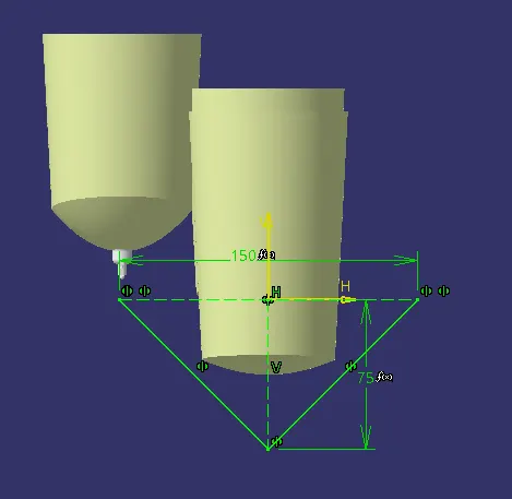
Fig 4
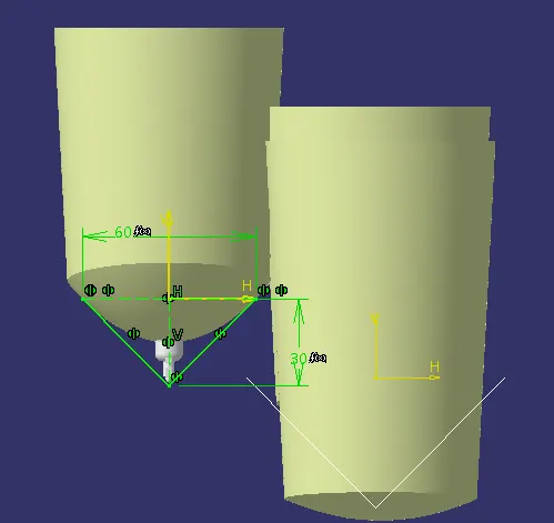
Fig 5
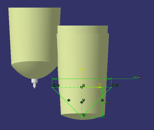
Fig 6
The above figures 4, 5 and 6 shows the sketches which were made in the initial stage for making the parabola's.
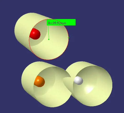
The circular surfaces of each reflector were made with same radius of approximately 40 mm as the minimum distances that should be maintained above the focal point should be above 30 mm and below the focal point should be 20 mm. Along the sides the minimum distance should be 20 mm. By taking 40 mm as the radius all the regulations are being followed along all direction and the reflectors are then designed in the circular shape which is shown below:
The below image shows that the back portion of the reflectors which were made using a parabola are dimentioned by using parameters and relations, which will be very usefull in the future when any change is required to be done.
After making the solid of the reflectors the bulbs are placed at their respective places.
1. W21/5W bulb is placed at the focal point of the tail stop reflector.
2. W21W bulb is placed at the focal point of the turn reflector.
3. W16W bulb is placed at the focal point of the reverse reflector.
3. Designing the housing for the lens.
The first step in designing the housing is to create the master section for the purpose of reference. In order to create the master section projection of the surroundings, welding track of housing and lens, lens solid body were taken into consideration and then sketch was developed by referring to which the housing can be designed.
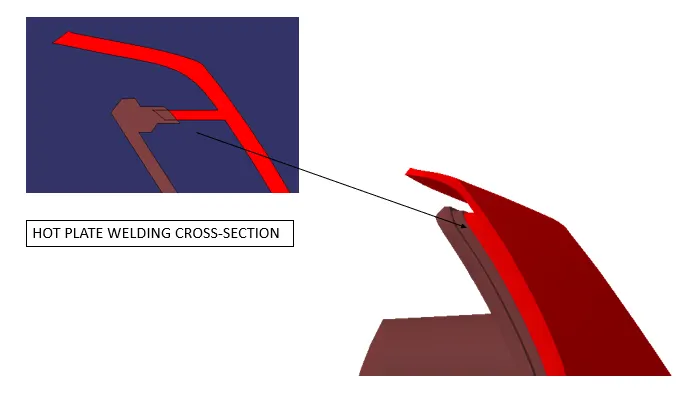
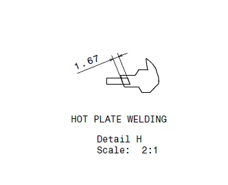
Hot plate welding technique was to be used to attach the housing with the lens, to accommodate this both the lens and housing welding track were designed as per hot plate section.
While creating the housing many industry factors were also taken into consideration making sure that there is no light leakage happening inside the lens.
Master section images
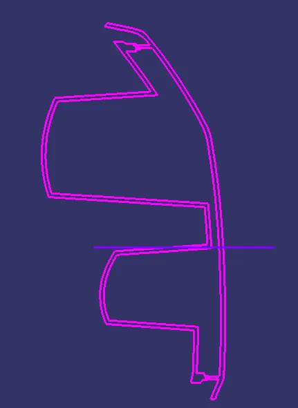

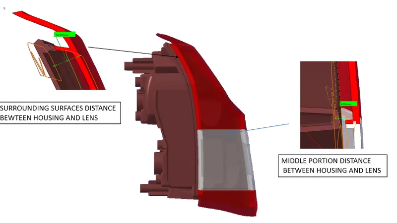
In the designing of housing a distance of 15 mm is maintained between the housing outer surrounding surface and the lens inner surface so that when hot plate welding operation is performed it does not affect the housing surfaces. The below image shows the approximate distance of 15 mm maintained. In the middle portion of housing is designed by taking into consideration that only 5mm distance should be there between the housing middle portion and the lens. This is made like this in order to avoid the phenomenon of Light Bleeding.
Light Bleeding : When there are more than one reflectors present in one housing than the lens should be designed in a way in which light bleeding should not happen. Bleeding of light happens when one colour of light intersects with another colour of light placed in same housing. If this happens clear colour of light won't be visible and thus the lighting will not give desired output.
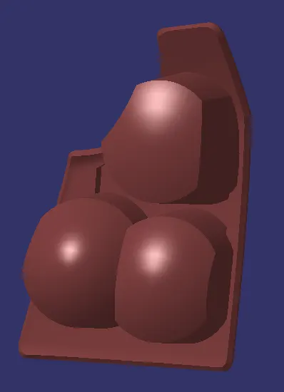
Housing front view image:
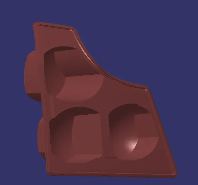
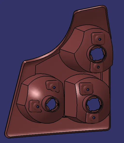
Housing back view image:
Hot plate welding cross-section image
Draft analysis was performed on the housing of the lens to check if the lens can be tooled along the tooling direction of the lens. A draft of 3 degrees was given on surfaces of the reflectors and the housing along the tooling direction so that the plastic component can be tooled easily.
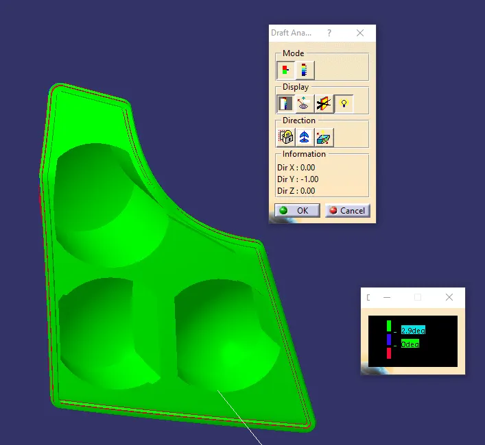
From the above draft analysis we can observe that the housing and reflectors designed on the housing can easily be tooled along the housing direction without any undercuts.
4. Designing the attachment features on the housing.
In order to fix the reflectors to the housing screw bosses were designed in a separate part called mounting and then after designing them they were placed at appropriate position and then union trimmed with the housing.
The below image shows the screw bosses fixed with the housing.
The cross-section of the mountings designed to fix the housing with the reflector is shown below:
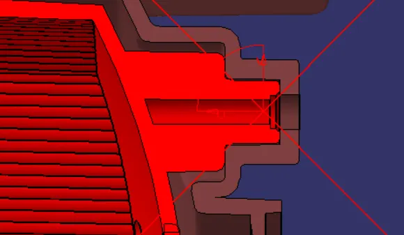
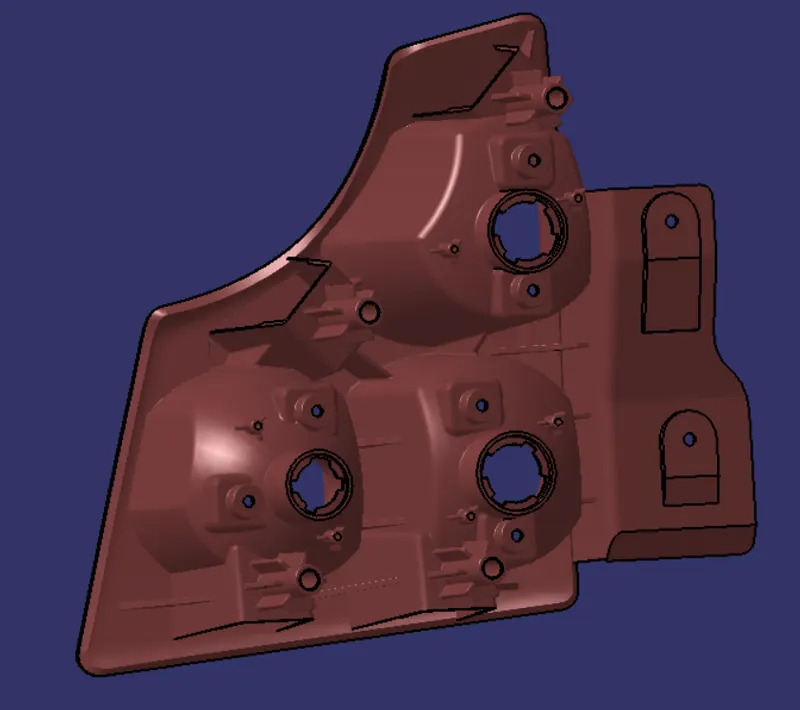
Fixing the lens assembly with the housing also requires screw bosses, for this purpose screw bosses which can insert M4 screws were also designed on top of the dog houses so that there are no plastic defects happening on the solid body of the lens after moulding process.
The below image shows the dog houses and the screw bosses.
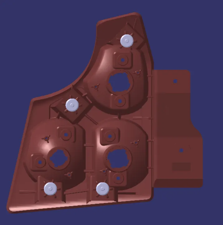
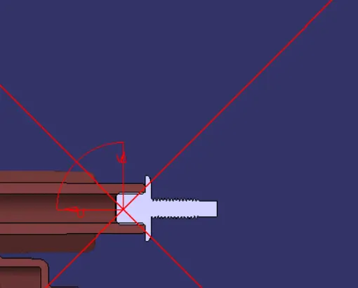
On top of the screw bosses of the dog house studs will be placed on it to fix it with the vehicle, screw boss along with the studs is shown below:
The cross-section view of the stud and screw boss is shown below:
It is also made sure that the dog house created should clear along the lifter tooling direction so that they can be tooled easily along this direction. The below image shows this through draft analysis performed on the dog house.
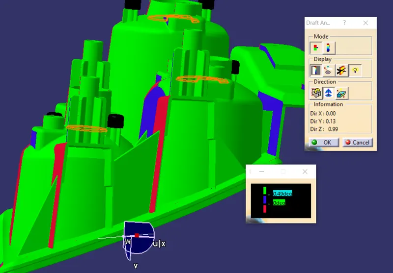
From the above draft analysis, we can observe that the dog house designed can easily be tooled along the lifter tooling direction as a draft of 0.5 degrees was given on each inside face of the dog house.
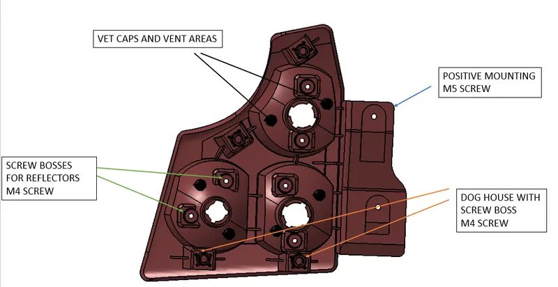
Positive mounting was also designed at one side of the housing which can be used to fix the housing with the vehicle with a M5 screw.
One of the major factors that needs to be considered while designing the lens is avoiding the phenomenon of condensation. Condensation occurs inside the lens housing due to the heat generated due to the bulbs and when there is a temperature difference between the surrounding then the lens will become unclear from inside. To avoid this situation vent areas are developed on the reflectors so that the heat generated can easily combe out from the back side of the reflectors and the temperature does not become high at those regions.
The placement of vents are also taken into consideration, which depends on these factors.
1. It should not be visible to the customer.
2. It should be easy for them to perform their functions.
3. It should not obstruct the flow of light or the light reflection.
Ribs are also designed on the required positions so that it can provide strength to the different mountings and reflectors present on the housing.
Positive mountings, vent areas along with the vent caps and ribs are shown below:
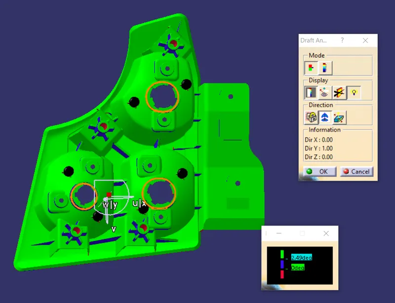
After completely making the housing and the adding the attachment features on the back side of it was also made sure that all these are made by giving draft on each outside face of the features so that they can be easily tooled along the housing tooling direction.
The below image shows the draft analysis performed on the back side of the housing by giving draft degree input as 2.49 degrees and it was concluded that the housing can easily be produced.
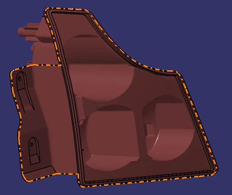
After performing the draft analysis parting line is made for the housing.
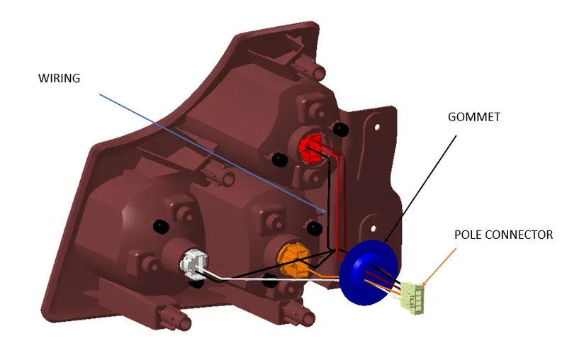
5. Designing of wiring harness
Every vehicle provides one wire each for 1 tail function, 1 ground, 1 turn function, 1 stop function, 1 reverse function. In our project we are being provided with 4 pole connector which provides all these wires coming out from it.
Colour of wire for each function
1. Tail stop function- 1 brown wire for tail function, 1 red wire for stop function, 1 black wire for ground.
2. Turn function - 1 orange wire for turn function, 1 black wire for ground.
3. Reverse function - 1 white wire for reverse function, 1 black wire for ground.
A Grommet is designed at the back side of the housing which functions as a connector between the pole connector and the wires coming out from the housing. At grommet additional wire can also be fixed to give more functions to the tamp.
The below image shows the wiring harness for tail lamp.
6. Final Products
- Lens final
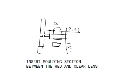
In order to incorporate all the three functions in the tail lamp, a clear lens is also designed along with the red lens, in order to make both the lens insert moulding technique will be used so that all the functions can be clearly visible and perform their function accurately.
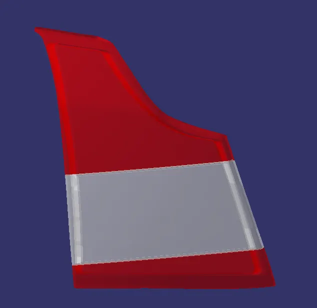
The insert moulding section of the two lens is shown below:
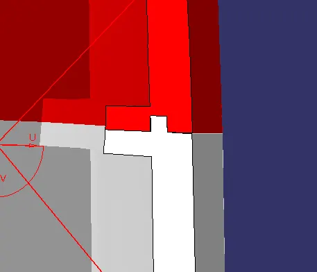
Insert moulding specification is shown below:
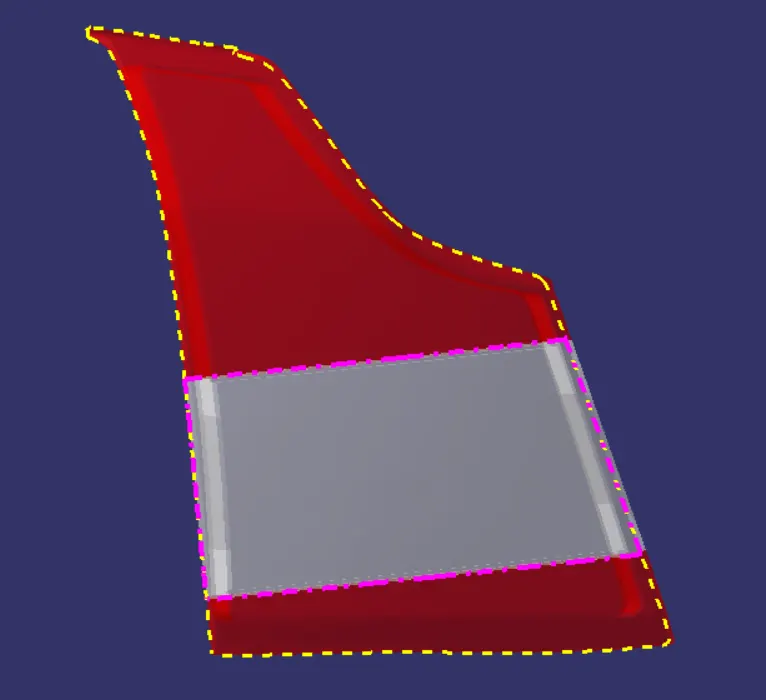
Parting line of the lens is made which will be used as the reference to separate the core and cavity while the moulding the lens. The below image shows the parting line of the lens.
2. Reflectors final
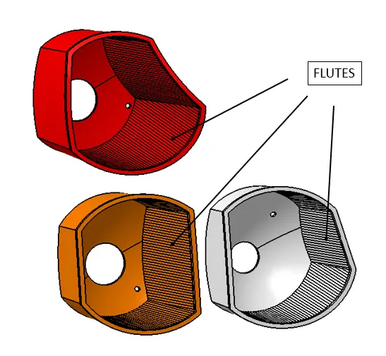
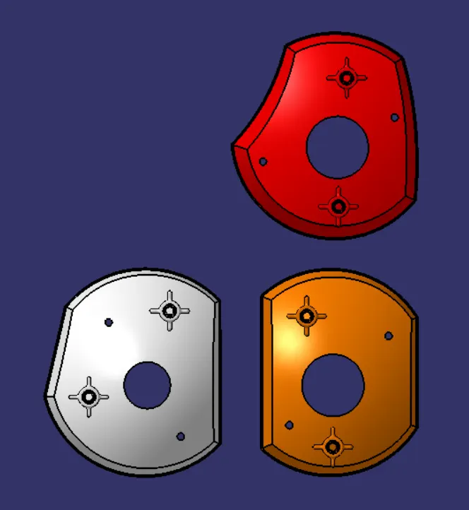
The light spreads in all the direction inside the reflector, in order to project most of this light rays outside flutes are designed on each side surfaces of the reflector so that all the light can be emitted in the outwards direction.
Reflector back view:
7. Assembly and child parts drafting:
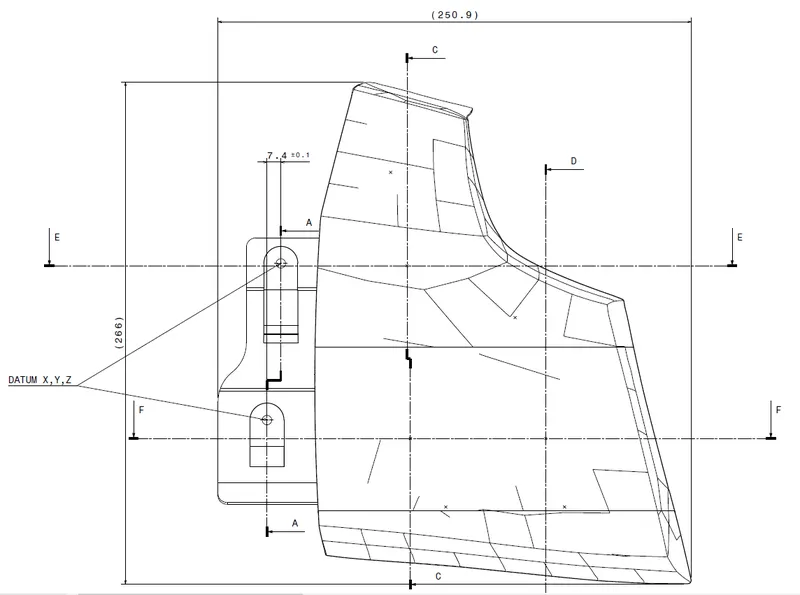
Dimensions and regulations for each part is shown through drafting
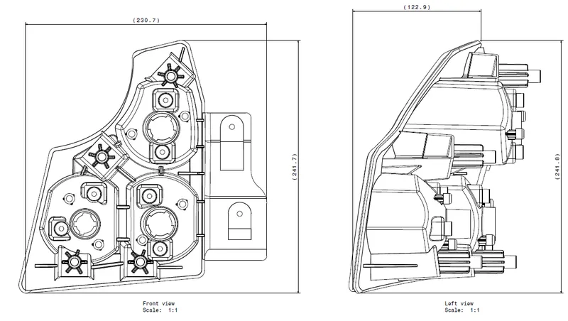
The casing dimensions of the les is shown below:
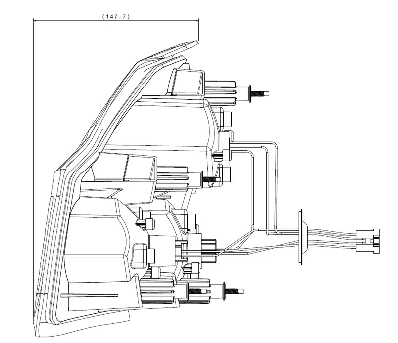
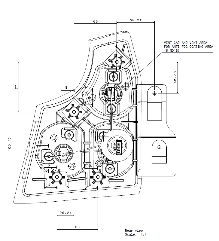
The regulations and important information that needs to be represented on the reflectors is shown below:
Tail stop lamp horizontal view:
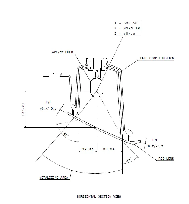
Tail stop and turn reflector vertical section is shown below:
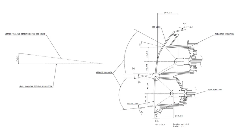
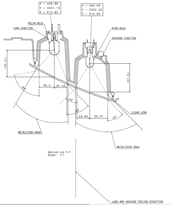
Turn and reverse reflector horizontal view is shown below:
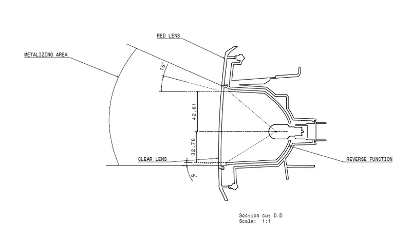
Reverse reflector vertical view:
Hot plate welding specification is shown below:
The specification of casing of housing is shown below:
Reflector child part drafting is shown below below:
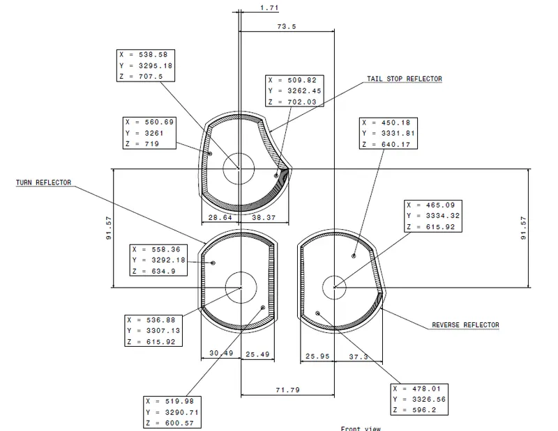
8. Bill of material
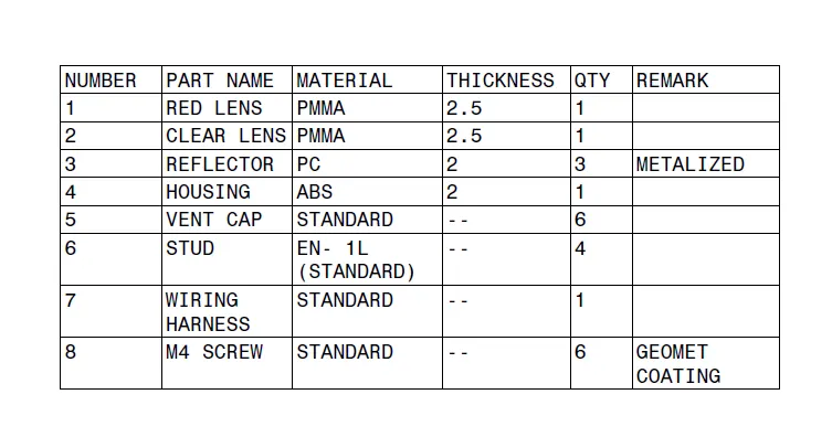
A bill of materials or product structure is a list of the raw materials, sub-assemblies, intermediate assemblies, sub-components, parts, and the quantities of each needed to manufacture an end product.
The below image shows the BOM for the Tail stop lamp
9. Tree Structure:
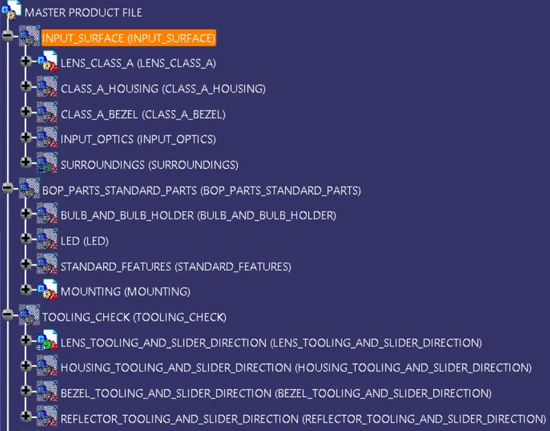
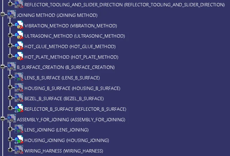
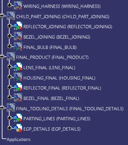
The detailed tree structure that was used to make each part of the Tail stop lamp in an organised manner is shown below:
CONCLUSION:
The assembly of the of the lens and housing was made successfully by following all industry standards.
1. The solid of lens and housing was made which can be attached together with hot plate welding.
2. Attachment features like mountings and screw bosses were designed at the back side of the housing to attach the housing to the vehicle and the reflector to the housing.
3. Draft analysis was performed on each stage to cross- check if the parts made can be easily tooled by giving draft on required faces of any part.
4. Drafting of the lens and housing assembly was made to represent the specifications of each part.
5. Bill of material was also presented to know all the information of the tail stop lamp.