Project 2
AIM : To Design and Develop a simulink model to understand Energy analysis of EVs on different driving cycles
OBJECTIVES : To prepare a technical report about the EV model including -
- System level configurations
- Model parameters
- Results
- Conclusion
THEORY :
- An Electric Vehicle (EV) is a vehicle that uses one or more electric motors or traction motors for propulsion.
- An electric vehicle may be powered through a collector system by electricity from off-vehicle sources, or may be self-contained with a battery, solar panels, fuel cells or an electric generator to convert fuel to electricity.
- EVs include, but are not limited to, road and rail vehicles, surface and underwater vessels, electric aircraft and electric spacecraft.
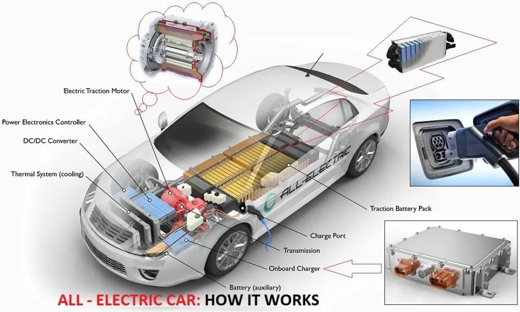
BLOCK DIAGRAM OF ELECTRIC CAR:
MAIN PARTS OF ELECTRIC CAR:
1)Motor:
In ICE vehicles gasoline engine as number of moving parts but in Ev insread of number of moving parts motor as only one moving part here the motor is choosed based upon the car system voltage AC motors are less expensive and aslo light in weight compared to the DC motors.
2)Battery:
The batteries are charged through the speciallly estabilshed power stations ,mainly in the Ev lithium ion batteries are used because of there performance and there price and lighter weight compare to other type of batteries,and aslo in ev other batteries like lead acid nickel batteries are used becuase of there advantages compare to that of the lithium ion batteries and lead acid batteries are used again and again like recycle
- Lithium-Ion Batteries : This battery technology gives extra performance and range. However, it also carries the highest price tag. Lithium-ion batteries are lighter than Lead acid and Nickel metal. These are also the batteries used in digital cameras and smartphones.
- Lead Acid Batteries : This battery technology is the most popular. It is also the cheapest among the battery technologies. What’s good about it is it’s 97% recyclable.
- Nickel Metal Hydride Batteries : This battery technology provides higher output and better performance but it costs much more than lead-acid batteries.
3)Power converters:
Here it used to convert the power which is required according to the vehicles performance and the system voltages
4)Motor controller:
This componet used in complete operation of the electric car and it mainly distribute the power at required moment in indicates al the vehicle operators like motor battery it consist of micro processor there are aslo different controllers which gives better results
5)Transmission:
Transmission is nothing but it is the flow of energy and it flows from the battery to the motor or engine
MATLAB MODEL OF ELECTRIC CAR :
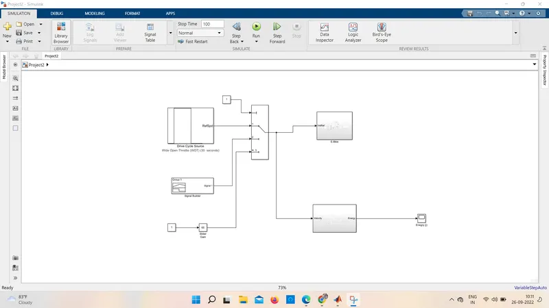
- Here the simulation run time is 2474 sec because this is the total time required for the input drive cycle source
- As we all know the scope are connected to know the results
- Here to convert the velocity from m/s to kmph we have used gain block
BLOCKS USED ABOVE MATLAB MODEL:
- Drive cycle source
- Controlled PWM voltage
- Longitudinal driver
- H- bridge
- Vehicle body subsytem
- DC motor
- Battery pack
- Battery state of charge
1] DRIVE CYCLE SOURCE:
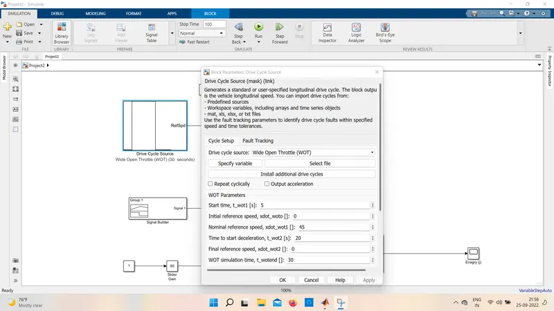
- Thedrive cycle source block is mainly used to give the reference speed to the simulation it mainly generates the specified longitudinal drive cycle to the user.
- It aslo consist of different cycle source like FTP75,wide open throttle workspace variable
- But here we selected drive cycle is FTP75
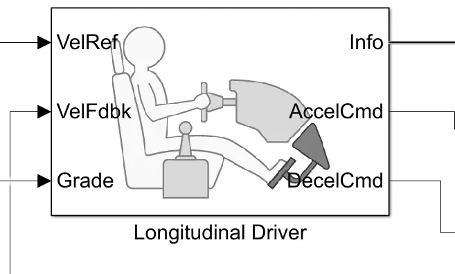
2] LONGITUDINAL DRIVER:
- This longitudinal driver block is in built block which is avaliable in the power train blockset
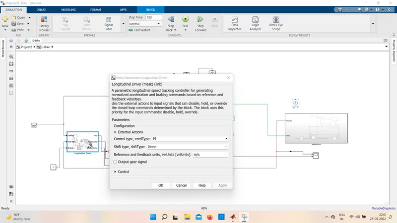
- It is mainly used as speed tracking controller for generating the acceleration and deacceleration commands i,e depends upon the reference and feedback.
- It mainly consist of 6 ports i,e 3 input ports and 3 outports
- VelRef port is mainly act as the reference port i,e wher the input is taken from the input drive cycle data is given
- VelFdbk port act as the feedback port to the longitudinal driver it is responsible to the feedback velocity here the actual velocity output given by the vehicle body is connected here it working as by comparing the actual velocity with the reference velocity it generates the acceleration and deacceleration commands.
- Grade port used mainly for the grade angle but here we are not considering any inclination so it is connected to the constant block zero
- AccelCmd and DecelCmd ports are responsible for the acceleration and deacceleration signals and further this ports are connected to the controlled PWM vlotage block
- Info port mainy used to give the output for the bus siginal for different calculations
Here we have used PI control type it mainly implements control with the tracking and feed forward and control gains are used as default as shown in below figure
3] H-BRIDGE CIRCUIT :
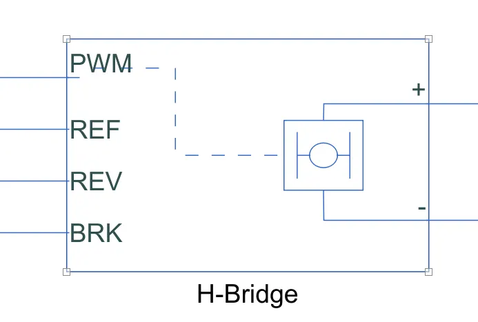
- The above block shows the H- bridge circuit this block can be run by the controlled pwm volatge block
- It consist of 6 ports i.e 4 inputs and 2 outputs
- Pwm port is act as when the motor is powerd if the given voltage is higher the threshold voltage then it is enable
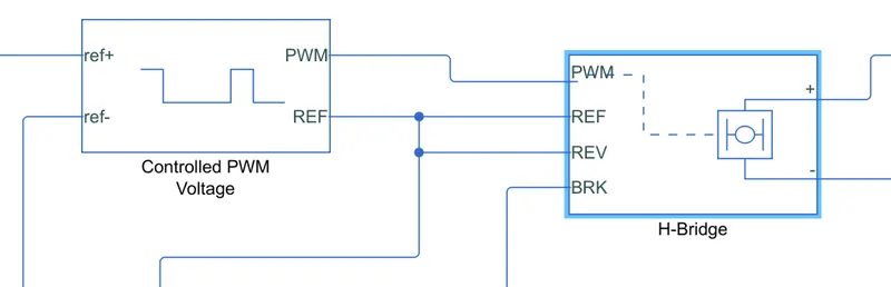
- Ref is act as the reference input port the combination of ref and pwm port gives the pluse input the H- bridge here ref is directly connected to the ground i.e electrical reference
- Rev port act as the reverse operation of the motor which is used in backward motion condition of the vehicle here we are not using any backward motion of the vehicle so this port is directly connected the ground i.e electrical reference
- Brk port is used for the barking of the vehicle
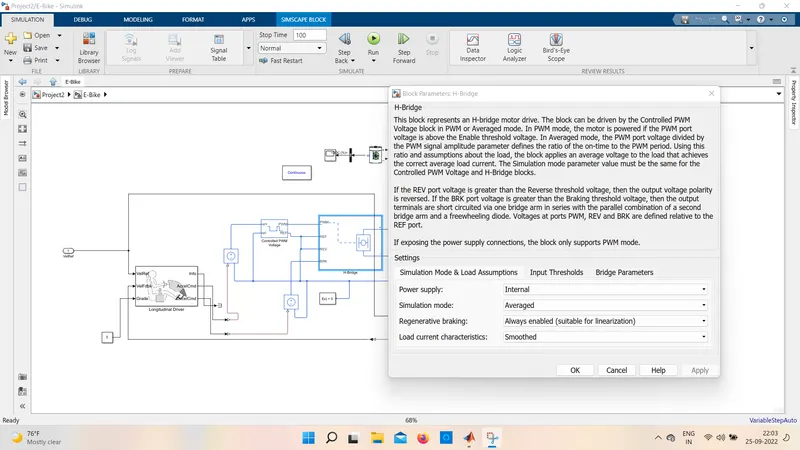
- Here the PWM mode takes much time in simulating the results so we have used averaged mode for the simulation and also load characterstics are taken as smoothed
- The regnerative braking option is taken as the always enabled which is suitable for the linearization
- when Brk input is conncted to the controlled voltage source it will genrates the emf which is responsible for the brakes applied
- The bridge paramters are taken when the ouput voltage amplitude is 300 and total brideg on resistance is 0.2 ohms aslo the freewheeling doide on the resistance is taken as 0.1 ohms
- The input thersholds are taken as default values as shown in below figure
- The combination of PWM voltage source and H-bridge is called as motor control unit
Motor control unit:
4] VEHICLE BODY SUBSYSTEM:
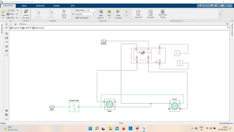
- Here for the above subsystem the input is taken as the rotational speed then this speed is given to the front axle through the simple gear block the drive ration is 3.7
- In tgis the rotaional direction of output is same as of the input
- And no meshing losses and viscous losses are not consider in this simulation
Main blocks of vehicle body subsystem:
- Tire
- vehicle body
1) TIRE:
- In this operation we used 4 tires i.e 2 front wheels and 2 rare wheels
- The tire as 4 ports like 2 inputs 2 outputs
- Here the N port tire act as the normal reaction and The A port act as the mechanical rotational port for the wheels so the two wheels on the same axle should have a connection through the port A
- The port H act as the mechincal translational port for the wheels so all the 4 wheels are connected to the H port and then to the vehicle body
- The port S indicates the slip of the tire
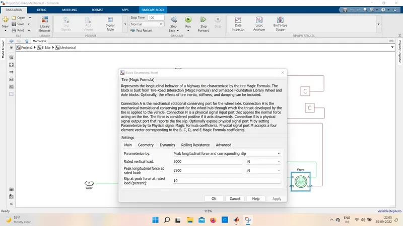
FRONT TYRE:
BACK TYRE:
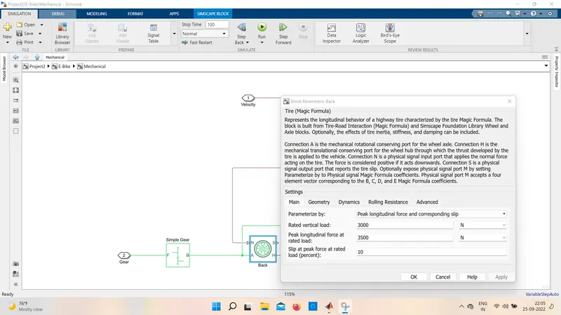
- Here the tire parameterize by the peak longitudinal and corresponding slip
- The rated vertical load and peak logintudinal force at rated load ,and slip at peak force at rated load are set to default values
- The paramters of the dynamics and rolling resustance are given as default i.e the tire is taken as 1kg-m^2 and radius is 0.3m the rolling resistance with constant coefficient is taken as 0.015
2) Vehicle body:
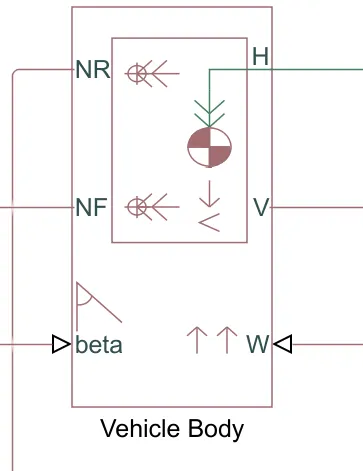
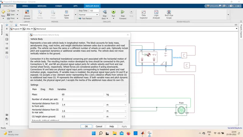
- The above 4 wheels are now connected to this vehicle body block
- This block in the system is used as the two axel longitudinal motion
- It consist of 6 ports as 3 inputs and 3 ouputs
- The NR and NF port indicates to output ports for the normal reaction forces on the front and rare axle
- The beta port is used as the inclination angle
- The port H indicates that the mechincal translational port
- V port indicates the real output of the translational velocity
- W port indicates headwind speed which is opposite in direction to the vehicle.
- Here the mass is taken as the 1200 kg default value as shown in above figure
- Drag force paramters are shown below
- And here the pitch and variables paramters are not considered in this simulation
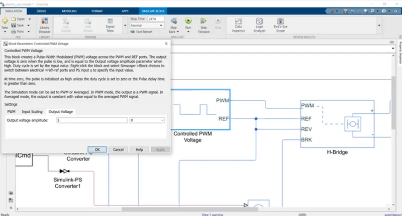
5] CONTROLLED PWM VOLTAGE:
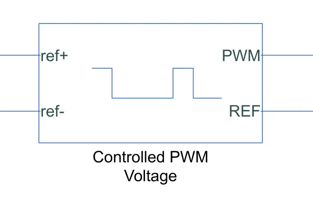
- This controlled pwm block is mainly used to provide the proper input siginals to the H- bridge block
- It mainly consist of the 4 ports i.e 2 input and 2 ouput
- The pwm and ref ports are directly connceted to the H- bridge circuit
- ref+ and ref- are the reference inputs responsible to the throttle inputs which are given by using driver this block mainly generates the required pluse width as per the given inputs
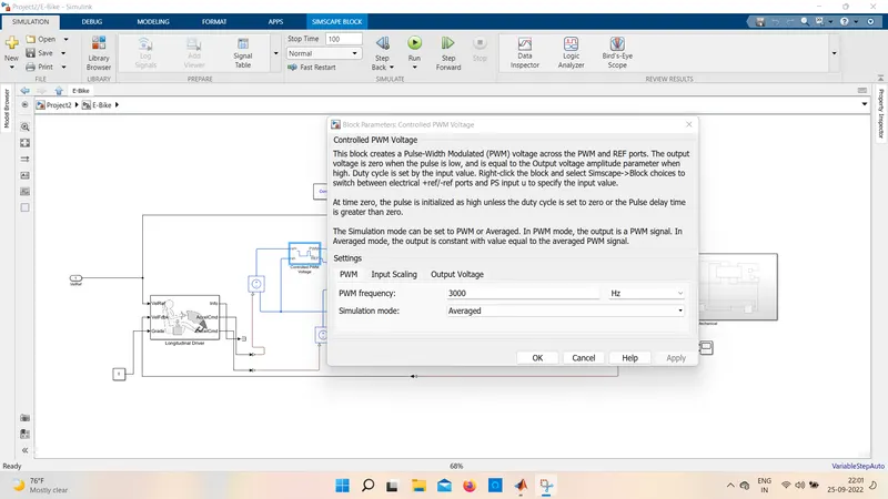
- In this the PWF frequency is 1000Hz and the simulation mode is average as shown in below figure
PWM:
Input scaling:
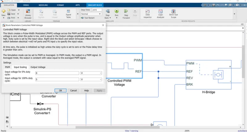
The input scaling is given as, for input volatge for 0% duty cycle is : 0 and for the input voltage for 100% duty cycle is : 5v
Output voltage:
6) DC MOTOR:
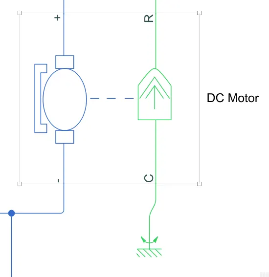
It is also a in bulit block which is used to convert the electrical inputs to mechanical outputs As seen in above figure it consist of blue colour on left side and green on right side. this indicates the left side blue colour indicates that it is a electrical input and green indicated as mechincal ouput
The below values shows the electrical torque paramters i.e feild type is taken as the permanent magnet and the model paramterization is taken as by rated load and speed
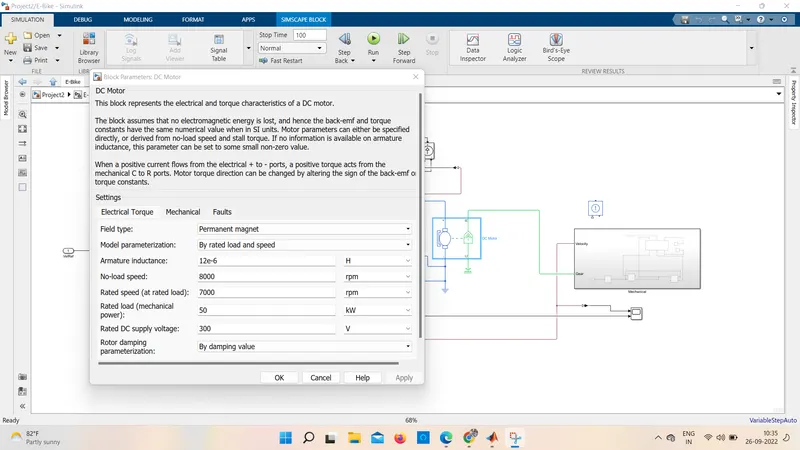
And here the mechanical paramters are taken as default
- In the dc motor block the R point indicates the rotor ouput and C indicates the casing so the R port is then connected to the input side of the vehicle subsytem and the C port is directly connected to the mechincal reference.
- similarily the postive and negative terminals are connected to the motor control unit i.e pwm volatge source and H- bridge if it is directly connceted to the battery the dc motor will run rated capacity so this eill results in no control of the DC motor and vehicle goes to top speed entrie simulation period so here the motor controller is very much neccessary
7) BATTERY PACK:
1)For this simulation we used a simple battery block because if we use other block the simulation time will be increased
2)In the above battery the option choosed is the charge capacity is finte if the chossen option is infinte then the voltage soucre would have been constant
3)And aslo here self discharing option is disabled
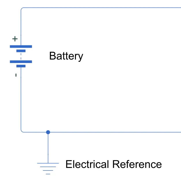
- The battery voltage is taken as 400v and amper hour rating is set default 50 v and remaining all values are set to default
- Here to get the battery supplies current as per the requriment of the motor controller not the rated current
- And here the current sensor and controlled current are combined and connected as shown in the figure
8)BATTERY SOC:
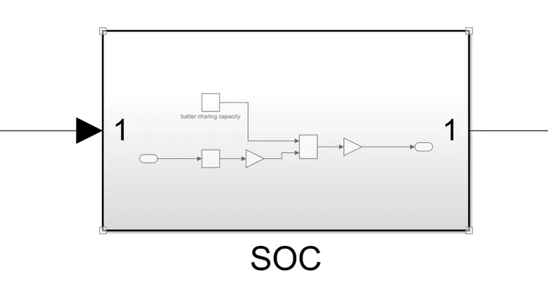
- Here for the calculation of SOC we have created a subsytem this subsystem takes the batteries current as input
- The process to calculate the Soc is to substract the charge from the rated capacity of the current
- Now this current is integrated by the integrator block with respect to the time
- And then the value now converted into ampere hours from coulumbs so the capcity of the battery becomes 0.06Ah
- Then the reamaining charge is converted in the percenatge of the battery charing capcity
RESULTS:
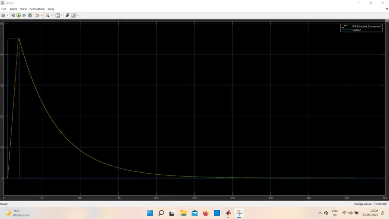
1)E-BIKE SCOPE:
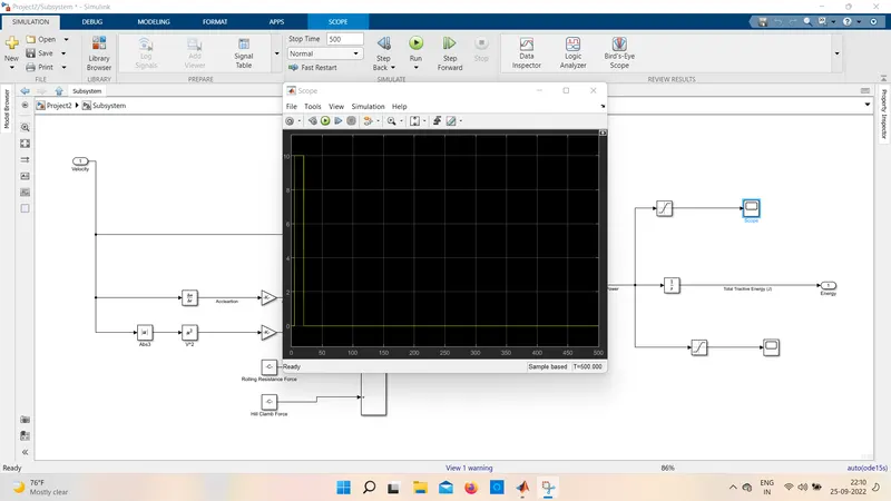
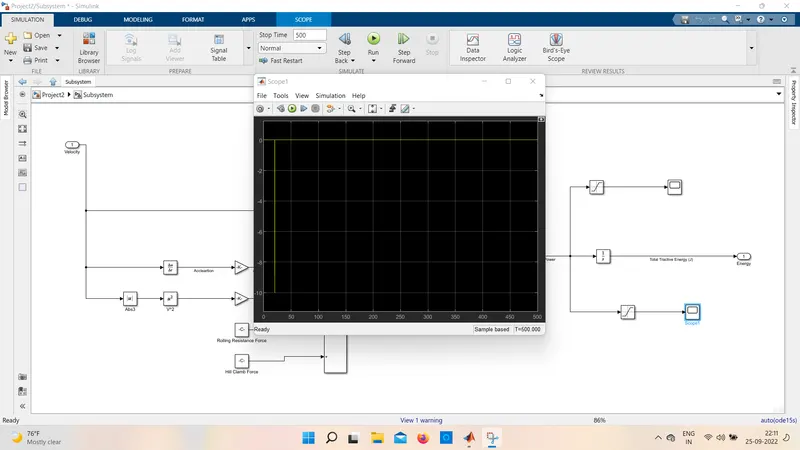
2)SUBSYSTEM SCOPE 1:
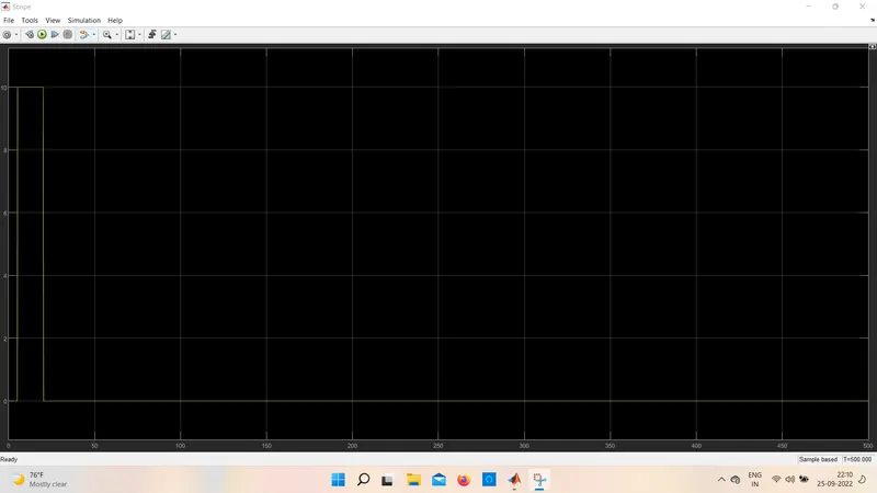
3)SUBSYSTEM SCOPE 2:
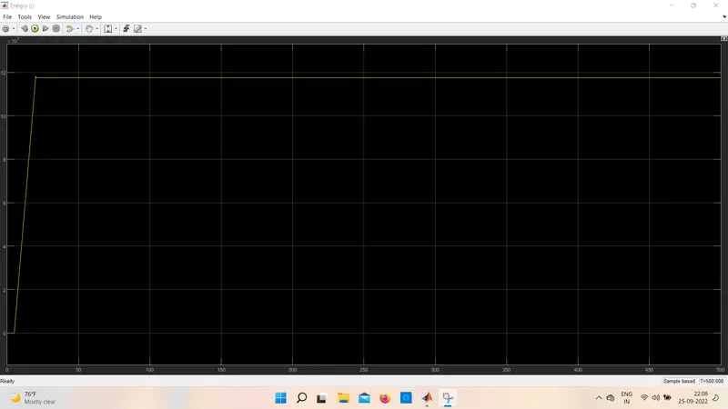
4)FINAL SCOPE:
CONCLUSION:
we have succesfully complete the given project
Design and Develop a simulink model to understand Energy analysis of EVs on different driving cycles