Pre-processing of a rear suspension model of an automobile in ANSA
AIM
The aim of this project is to perform pre-processing operations on a rear suspension model of an automobile. Pre-processing stages include geometry cleanup and topology optimization followed by mid-surface extraction if required post to which the model is meshed either using shell or volume mesh based on the model. Finally, necessary connections have to be created to set-up the model to behave accurately during the solver and post-processing stages
PROCEDURE
1. IMPORT REQUIRED MODEL FILES
The CAD geometry of rear suspension model in the format of .iges, .sldprt, .x_t, etc.. can be imported on ANSA using the File - Open command.
2. TOPOLOGY OPTIMIZATION
Initially, every model has to be checked for geometrical errors. Prior to this, it is best practice to perform a topology clear up to make sure that continuity is maintained between every cons and that it doesn't display double cons as single cons.
Prior to checking the model for geometrical errors, the hot points in the model are refined to a nodal spacing (average target length) of 3 for both the perimeter and macro part of the model
Then a topology cleanup is performed on the model using the topo operation in the FACES block of the TOPO module.
Finally, the model is checked for geometrical errors in the check manager. If any errors in triple/single cons arise, ANSA in most cases would be able to clear it using the FIX command.
ANSA can give a layout of all the geometrical error from our component model.
To perform geometric checks, Checks - Geometry - Select required params
ANSA is also capable of clearing small geometrical errors if it's within its capability and based on memory allocated for it. IF the model passes for topology cleanup the following image can be then visualized.
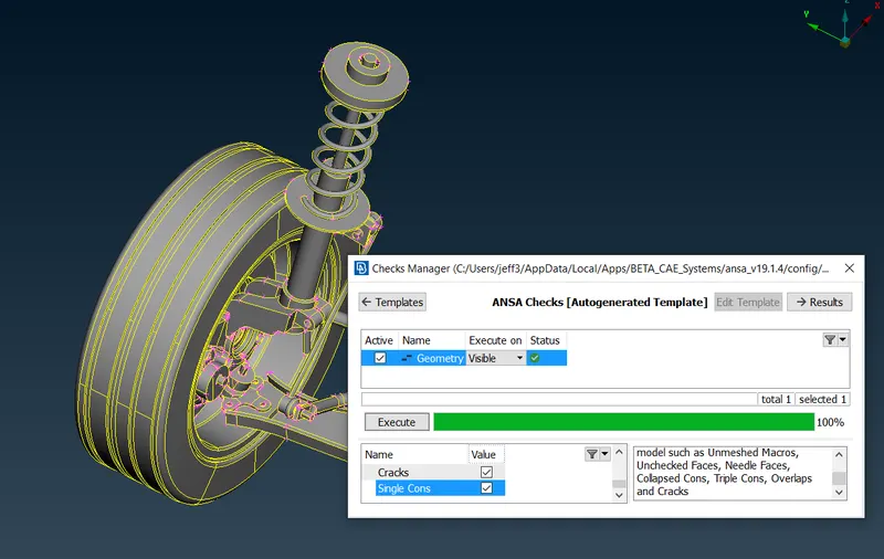
Fig 1: Geometry checks
3. MID-SURFACE EXTRACTION
Since this model contains many components with each component having a thickness that varies from others, it is recommended to segregate them into individual parts. This segregation can also be useful when extracting the mid surface of a component. Since all components have varying thickness it is perfereable if some of the compoennts or features can be extracted for mid because simplifying a geometrical feature is a more useful way of solving the model in the solver stages.
In our case, the thickness of components that are less than 5mm will be extracted for mid surface since the underlying principle is that if the thickness of the feature is negligible compared to the other two dimensions then mid surface is preferred for simplification.
Each model can be seperated from the rest using the !NOT command while the PID region option is highlighted.
Initially the model comes with 3 PIDs segregating the wheel, rim and the suspension. We segregate the suspension mechanism individually then measure the thickness using the measure command. Finally any component that falls within our user defined tolerance limit i.e 5mm can be extracted for mid either using the Offset command or the Middle command if the model is symmetrical.
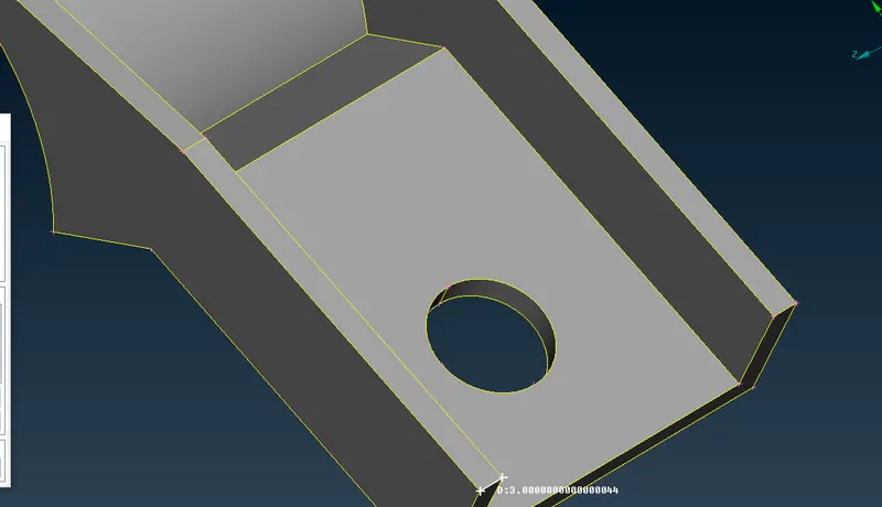
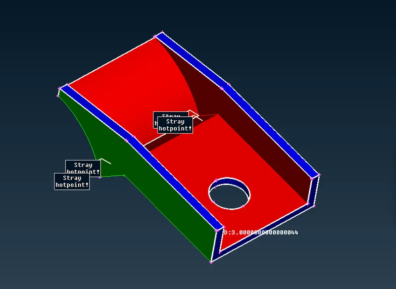
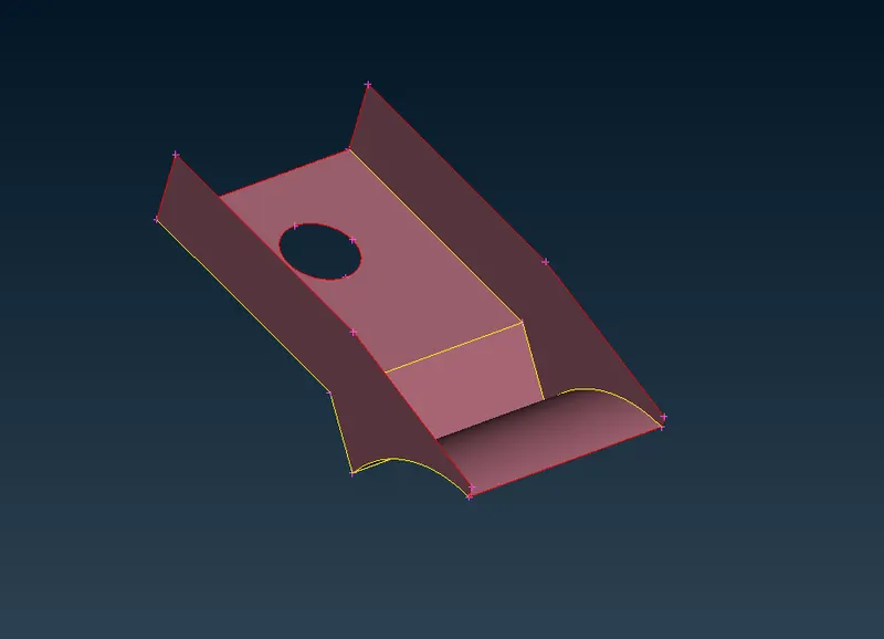
Fig 2: Mid-surface extraction of bracket
4. ASSIGNING PID
Similarly any other PID regions or Entities can be excluded from the rest and measured for thickness and whichever falls within our tolerance limit of 5mm can be extracted for mid using offset or middle command or even mid-surf - skin command.
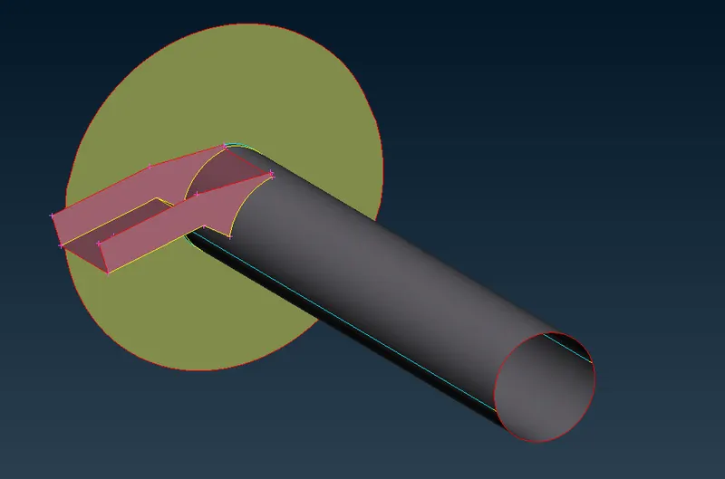
Fig 3: Mid surface extraction (for t< 5mm)
In total 4 components have been well within 5mm of thickness and have been extracted for mid-surface and assigned respective PID's with individual thickness
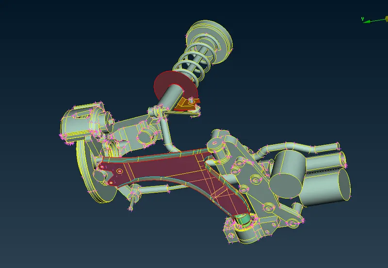
Fig Mid-surfaced components
5. SHELL MESHING
Prior to meshing the user has to define the required mesh parameters. ANSA tries to follow this input data to give a more precise mesh. However, in some cases, these mesh characteristics of the generated mesh may deviate from the user-defined parameters. Hence, to obtain a more accurate mesh we set up the quality criteria to check for those elements that fail the defined parameters.
These failing elements can then be reconstructed using ANSA's efficient mesh refinement algorithms in the MESH module.
Only features and components whose mid-surface are extracted are meshed only using shell mesh or 2D mesh elements like quads and trias. The set mesh parameters are of a target length of 4mm.
Hence the perimeter and macro lengths are set as 4mm in the mesh module then using spot mesh mixed mesh consisting of both quads and trias are formed.
In case of braket, since it has a hole, frst the number of nodes on its perimeter of the hole must be made even.
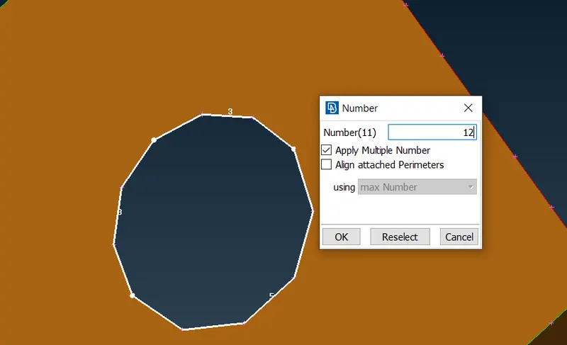
Fig 4: Setting even no nodes at hole edges
Then for holes, a zone cut is created prior to mesh generation in the Topo module. A zone cut equivalent to the length of the target length is made with a single layer as shown below
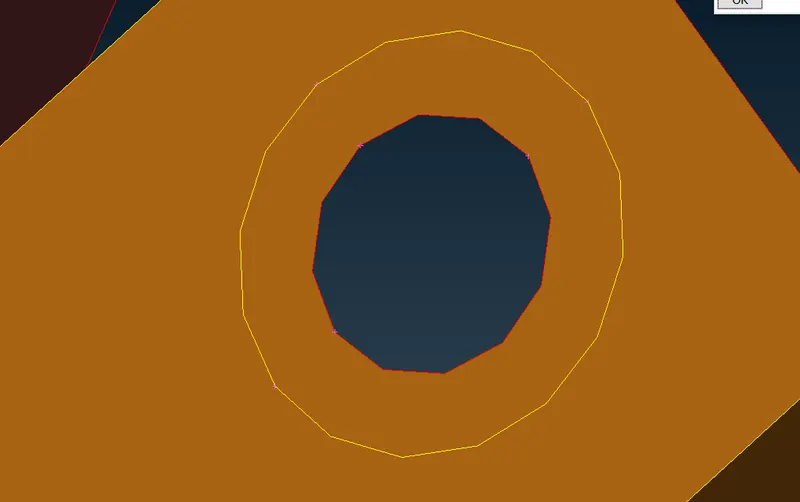
Fig 5: Zone cut
Then the mid surface is meshed using spot mesh method and reconstructed to get a more accurate result. Simultaneously any element that could eventuall fail are corrected and trias at edges of holes are swaped to its above quad element and back to back trias are similarly swapped or joined.
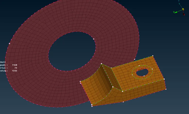
Fig 6: Shell mesh on mid surface
To check for deviating elements, the quality criteria for min and max length are chosen and its values are 1 and 5 respectively. Similarly, the tet collapse of the to-be generated volume mesh is also selected for error checks with a value of 0.2. Hence, any mesh that doesn't fall in the above-defined shell or solid mesh criteria can then be refined using any one of ANSA's inbuilt features.
Right after the shell mesh is generated these mesh elements are checked for quality based on the below requirements
Minimum Length
2
Maximum Length
6
Aspect
3
Warpage
15
Skewness
45
Jacobian
0.7
Minimum Quad Angle
45
Maximum Quad Angle
135
Minimum Tria Angle
30
Maximum Tria Angle
120
- Performing another reconstruct operation on violating elements towards a zone of 1 will clear most off elements
- Elements that fail for aspect/min or max length can be cleared using split, swap or join commands
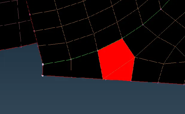
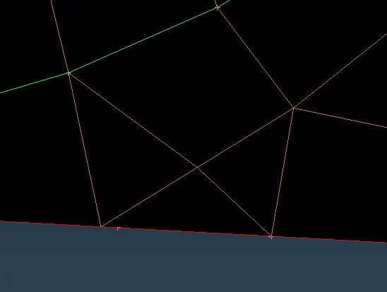
Fig 7: Shell mesh refinement
To generate the mesh we make use of the spot mesh generation feature in the MESH module. This feature allows us to capture certain regions or surfaces of the component that are enclosed within the cons. This helps us generate both trias and ortho trias at required surfaces thereby the whole components don't necessarily have to be modeled just by one.
Finally every mid-surfaced component are meshed using tria and quad elements and refined to pass the set quality criteras.
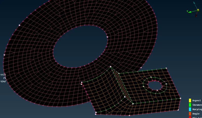
Fig 8: Refined shell mesh
Similarly other components can also be extracted if t< 5mm
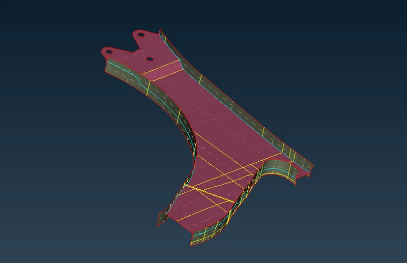
Fig 9: Mid surface component
DEFEATURING must be performed prior to meshing the component. Defeaturing using macros - cut feature is useful and can create a more appropriate mesh flow. Also creating zone cuts at appropriate areas.
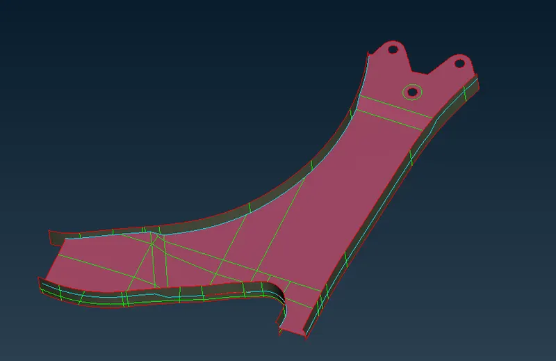
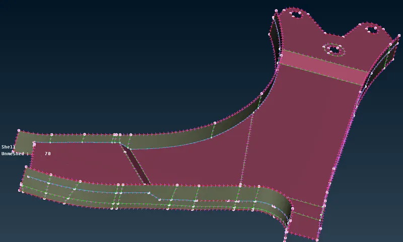
Fig 10: Defeaturing
Finally all the mid-surface components were defeatured and meshed using shell elements
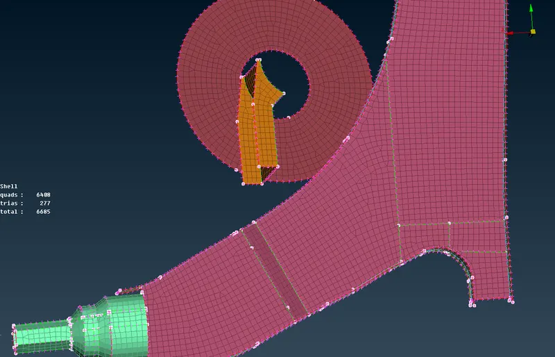
Fig 11 Shell mesh on mid-surface component
Meshing other components that haven't been extracted for mid-surface is less tedious compared to the above process. Each part like Rims, Tyres have different mesh parameters and quality criteria.
In case of Tyre, the required mesh target length is about 6.5mm. This can be accomplished by changing the required parameter and using spot mesh to generate mesh elements. Since the tyre is a fairly large model, it is very easy for ANSA to generate more quad than tria elements on the model.
Any element that fails for quality criteria for min/max length and skewness can be corrected easily. For ex: Elements that fail due to improper length (max) can be cleared by inserting a cut operation (as shown below)
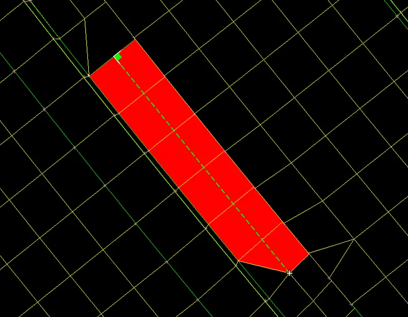
Fig 12: Mesh refinement on tyre component
In case of the rims, a washer cannot be inserted on the surface around the bolt holes as it would cause errors at min length since the nodal spacing would interfere with the washer area. However the number of nodes at these holes must be ensured they stay at even and its edges must be parallel to a adjacent surface con.
Finally the Tyre and Rims are mesh using the same mesh parameters only on the surface.
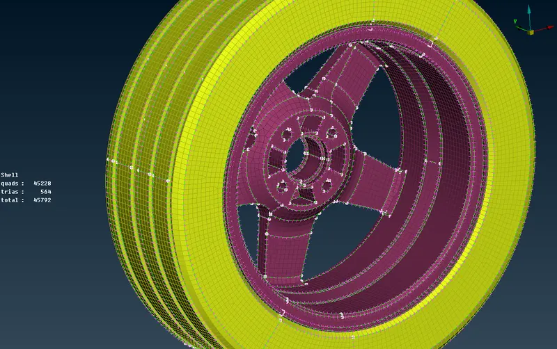
Fig 13: Shell mesh generation on Tyre and Rim
6. VOLUME MESH
To create a solid mesh using the ANSA inbuilt unstructured mesh command, a volume has to be defined prior to mesh generation. The basic process by which a mesh is generated across the volume is by mapping the surface meshed elements on either side of the component.
The parts and components that have been meshed using the 2D elements and refined in the MESH module are then defined as a seperate volume to create a volume mesh using tetra elements
- In the Volume module, define the volume of the component. Prior to this the component has to be made of closed volume. Then using the auto detect feature the visible component can be defined as a individual volume
- The closed defined volume is remeshed using any of the volume mesh algorithms - Tetra Rapid or Tetra FEM.
- The tetra mesh is generated by mapping each component to its opposite surface
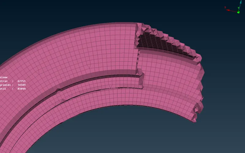
Fig 14: Volume mesh on tyre
Finally as done for surface meshing, the solid mesh elements should be check for quality errors. The main mesh quality criteria for a tetra mesh element is tet collapse (in this case, a value of 0.2)
The default value that most solvers check for is 0.75. However, a value of 0.2 is respectable in most cases depending upon the model and its application.
If any tet collapse failure occurs it can be cleared using the Fix quality operation or by moving the grid.
SImilarly the same is done for the Rim component.
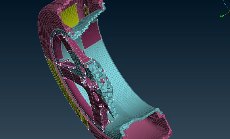
Fig 15: Solid meshing on Tyre and Rim
Similarly other components in the mechanism are seperated individually and meshed first using shell elements and then using solid mesh elements like tetras.
The mesh parameters for the other components vary to the ones modeled with the tyre and rim component. For these components a target length of 4mm is set.
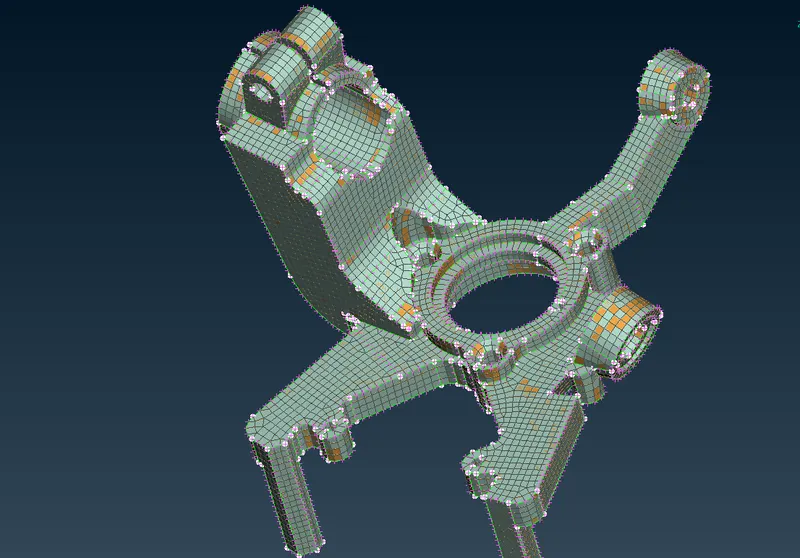
Fig 16: Solid mesh of steering knuckle
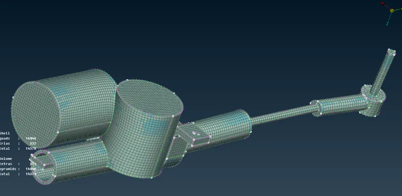
Fig 17: Volume mesh of Tie rod
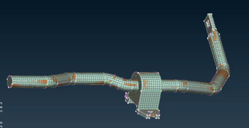
Fig 18: Volume mesh of sway bar
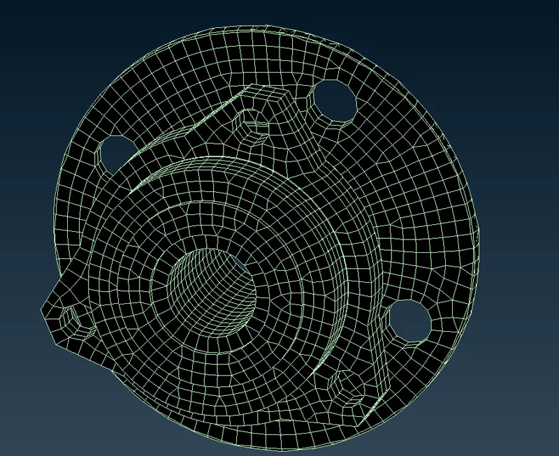
Fig 19: Solid mesh of Wheel hub
Finally every componet has been meshed using both shell and solid mesh elements.
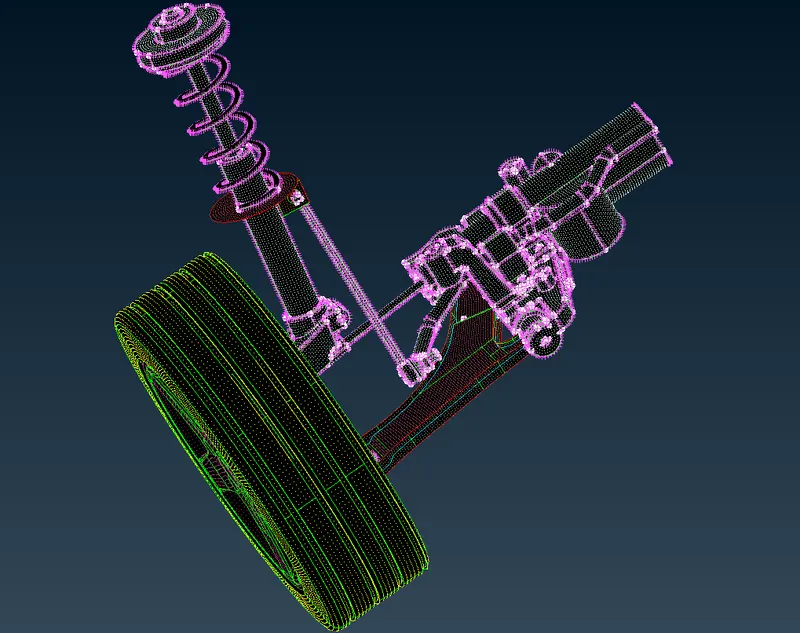
Fig 20: Volume mesh
7. CONNECTIONS
Pre-processing softwares like ANSA, HM come with in-built solver decks which contain the necessary features that are present in the original solver like LS-DYNA, NASTRAN. However these in-built decks are in no ways a mean of replacement for the original software since the solver algorithm is not in-builit in them rather they act as a means of making the model prepared (pre-processing) to export it onto the real solver for computation.
The type of solver deck chosen is mainly dependent on the type of application the model is used to perform. For ex, NASTRAN is widely popular in the NVH domain hence, our case, which involves a car door is pre-processed using NASTRAN elements so that it can finally be exported onto the NASTRAN solver for NVH analysis.
Connections can be made using the NASTRAN deck. However there are many other solver decks that are available and the preferred one puerly depends on the application i.e durability, NVH, crash etc.
The spring element can be modeled as a CBAR element. To accomplish this the alignment of the spring has to be made out using curves.
- Create a curve between the middle of the edge of the cons of the spring. Curves - Middle - select 1 group - select the 2nd group.
- The using the connect - multi option the curve can be joined into one.
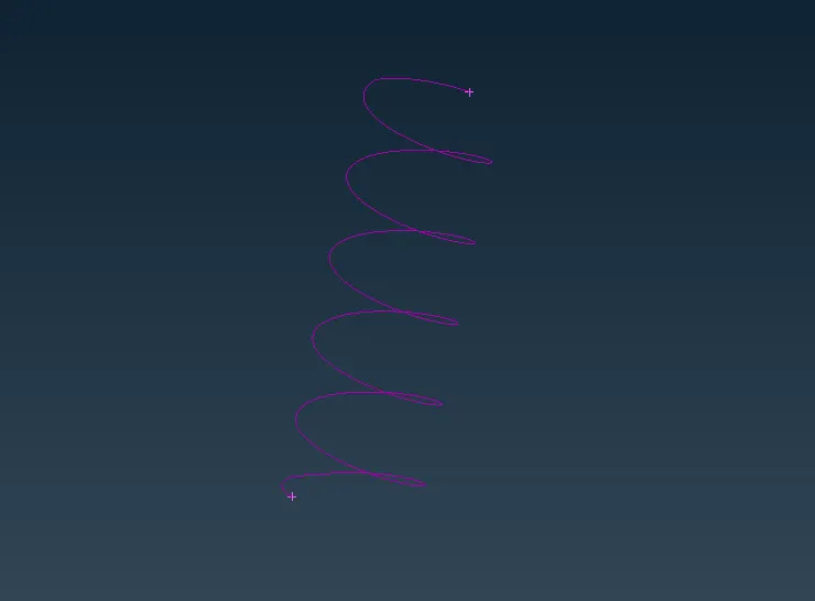
- Then the CBAR element from the NASTRAN deck is selected and the defined curve is selected.
- A new property for the 1D bar is created and a new CBAR is then created specifying the number of elements in the spring element.
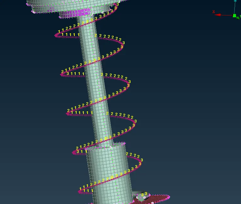
Fig 21: Spring modeled as CBAR element
Seam welds can be deployed as follows,
- Create a curve using create or cons2curve command to define the length and shape of the seam weld
- Use convert to curves option to convert into a seam line
- From the connections manager select a OFFSET SHELL weld element and defined the property of the 2 components where the weld of the element has to be deployed
- Specify the search distance, weld type, zone length etc.
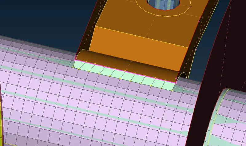
Fig 22: seam weld
To model a bolt connection two RBE2 elements can be created at the ends of the component and the washer can also be included and finally a RBE2 using 2 nodes can be used to model the stem segment of the bolt.
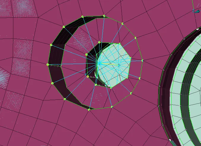
Fig 23: BOlt connections
Similarly, other RBE2 elements can be deployed as a means of multi-point constraint feature at edges and holes.
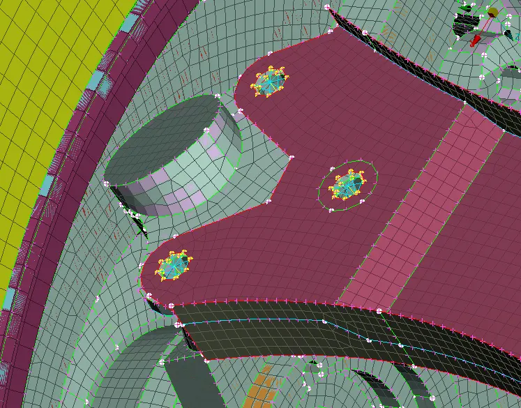
Fig 24: RBE2 elements
Finally all the connections have been made and all mid-surfaced component and volume components were meshed using shell and solid mesh respectively.
Now that a half-part of the model has been pre-processed completely we can use the symmetry transform command to copy the half part of the model onto the other side.
To accomplish this:
- In the transform command - select symmetrical
- To specify the orientation of the plane, select Mirror 3 points plane.
- Select 3 points that are parallel on the right end of the model. The 3 points must be parallel so that the plane isnt created as inclined rather parallel to the model end surface.
The final model is shown below.
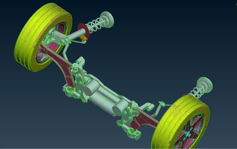
Fig 25: Pre-processed model
CONCLUSION
Hence the following operations have been performed on the rear suspension model:
- Cleared for geometrical errors
- Topology optimization
- Mid-surface extraction
- Shell meshing using trias, ortho trias and quads
- Volume meshing
- Creating connections like rigid elements and welds using the Nastran deck
- Mirroring the model half
LEARNING OUTCOMES
Gained knowledge on,
1. Extracting mid-surface using offset, mid-surface and middle command
2. Shell meshing using quads and trias
3. Volume mesh generation using Tetra Rapid and Tetra FEM method
4. Creating connections using the Nastran deck
MODEL FILE:
https://drive.google.com/file/d/14Brw9zx0LJVCpPb_FMTuvLl_dh9-C4Qv/view?usp=sharing