Project 2
Introduction
The interior permanent magnet synchronous motor (PMSM) can offer many advantages, including high power-to-weight ratio, high efficiency, rugged construction, low cogging torque and the capability of reluctance torque.
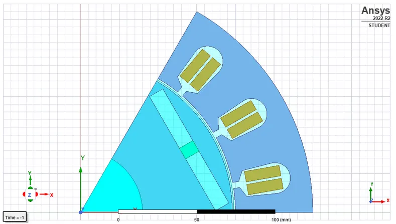
18 slots were assigned for the stator and 3 pole pairs for the rotor.
The first thing is the consideration of torque and speed requirements. Since this is a 10kW motor, it is used for HEV (mild hybrid) applications with a low degree of hybridisation. And can be operated by a 24V 400Ah battery (say).
Usually starting torque is provided by the motor (note that this is also not a self-starting motor),
And torque requirement = 150Nm
Motor Torque: 150Nm
Motor Speed: 636.619 rpm
Designing Motor
Stator Parameters
| Outer Diameter | 300mm |
| Inner Diameter | 200mm |
| Length | 300mm |
| Stacking Factor | 0.95 |
Slot Parameters
Number of Slots: 18
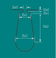
| Hs0 | 4mm |
| Hs1 | 3.5mm |
| Hs2 | 20mm |
| Bs0 | 4mm |
| Bs1 | 17mm |
| Bs2 | 20mm |
Winding Parameter
| Winding Layers | 2 |
| Parallel Branches | |
| Conductors per slot | 12 |
| Number of Strands | 1 |
| Coil Pitch | 1 |
Pitch of the slot, p = pi * inner diameter / Number of slots
Design Considerations;
- 3p<Hs2<7p (need to make sure that it fits in the given specifications stator parameters)
- 0.4p<Bs1<0.6p
- 0.1Bs1<Bs0<0.5Bs1
- 0.1Bs1<Hs0<0.5Bs1
- 0.1Bs1<Hs1<0.5Bs1
Rotor Parameters
| Outer Diameter | 196mm |
| Inner Diameter | 80mm |
| Length | 120mm |
| Steel Type | M27_29G |
| Stacking Factor | 0.95 |
Outer diameter was designed assuming an airgap length of 2mm.
Pole Parameters
| Embrace | 0.88 |
| Bridge | 2mm |
| Magnet Type | VACODYM 764TP |
| Magnet Width | 8mm |
| Magnet Thickness | 10mm |
- Embrace was chosen by iterative design, observing the picture generated by RMXprt, making magnets as close as possible.
- Magnetic thickness was designed using TRV calculation where Length of core*inner Diameter^2 / torque was set to 20.
Simulation
The model was simulated in ANSYS student RMXprt, results were obtained and files are attached.
(Note: ANSYS student does not support Maxwell transient simulations)
Results
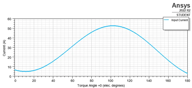
Current vs torque angle
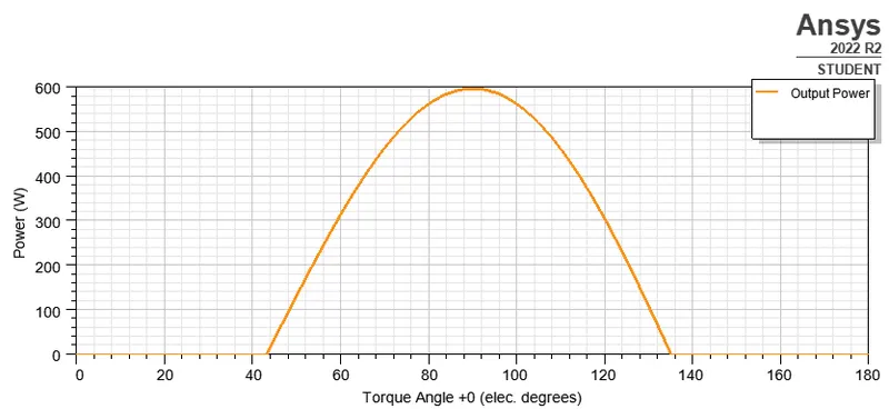
Torque Angle vs Power
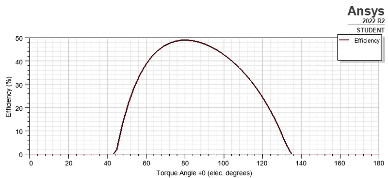
Efficiency vs Torque Angle
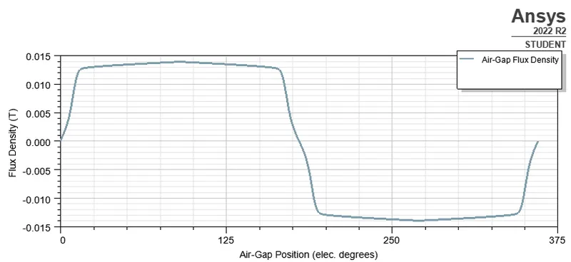
Flux Density vs Position
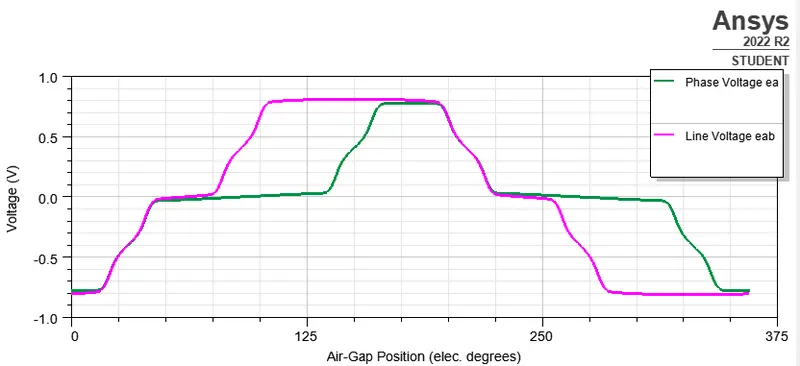
Induced Voltages at Rated Speeds
References
- https://ieeexplore.ieee.org/document/8728442
- https://iopscience.iop.org/article/10.1088/1755-1315/100/1/012160/pdf
- https://ieeexplore.ieee.org/document/9304526
- https://ieeexplore.ieee.org/document/8493159
Remarks
- Due to the less time available, the design choices were not perfect. (I could explore more on windings, magnetic material and also design of inner rotor diameter which can be measured using failure analysis on shaft with the torque considerations etc.)
- Ansys student does not support Maxwell transient analysis, so those results were not obtained.