Midsurface extraction and 2D meshing for floor panel of a car
Objective:
The objective here is to extract the midsurface and generate a 2D shell mesh of the given floor panel (spare wheel well) model of a car. The target element length for the mesh is 5mm and the mesh needs to follow the following quality criteria.
| S.N | Quality Criteria | Value |
| 1 | Aspect Ratio | 5 |
| 2 | Skewness | 45 |
| 3 | Warping | 15 |
| 4 | Taper | 0.5 |
| 5 | Min. Length | 2mm |
| 6 | Max. Length | 8mm |
| 7 | Min angle Quad | 45 |
| 8 | Max angle Quad | 135 |
| 9 | Min angle Tria | 20 |
| 10 | Max angle Tria | 120 |
| 10 | Tria % | 10 |
Procedure:
The floor panel is a large sheet metal stamping that often incorporates several smaller welded stampings to form the floor of a large vehicle and the position of its external and structural panels. For this project, we have the following model of the spare wheel well floor panel of a car. This panel makes the trunk's floor in most of the passenger cars. And is used to keep the spare wheel and also tools.

This is a sheet metal component with a very small thickness and therefore, a 2D shell mesh is preferred over 3D mesh. The 2D shell mesh would give faster analysis results without affecting the accuracy. The whole pre-processing process for such component is as follows:
- Import the geometry, and analyze and understand the model properly
- Check for errors in the model like missing surfaces, intersecting surfaces, etc. and repair if any
- Extract the midsurface
- Perform geometry cleanup on the extracted midsurface to resolve any geometrical errors and make it ready for meshing
- Generate 2D mesh for the midsurface
- Check for quality criteria and repair failing elements
- Assign property and material to the mesh
First, the model was opened into the Hypermesh Optistruct workspace and analyzed. There were several geometrical errors because of missing surfaces, and intersecting/duplicate surfaces, for eg. shown in the image below.
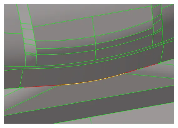
Red edges indicate that some surface is missing there and yellow edge indicates that some duplicate surface is there. These errors can be resolved by either creating the missing surfaces or just joining the edges using the replace point tool and deleting the duplicate surface. But there are a lot of such errors, and therefore won't be productive to spend time on it. Instead, it was decided to perform manual midsurfacing. For that, only the outer surface of the model was repaired for missing surfaces.
Before extracting the midsurface manually, first, the thickness of the component needs to be measured which can be done using the distance tool under Geom tool panel. The thickness of the component was found to be 0.75mm.
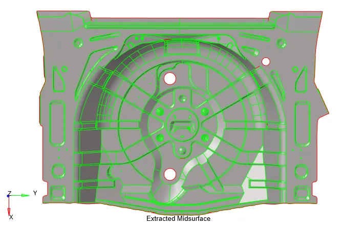
Next, midsurface is extracted using the Offset tool under the Geom>surface edit>offset tool panel. All the outer surfaces were selected by face and then duplicated to a newly created component and offset value was configured to half of the thickness of component, i.e., 0.375mm. The extracted midsurface is shown in the image below.
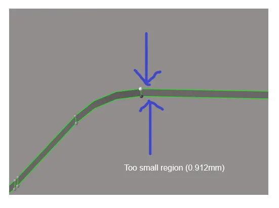
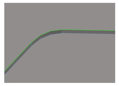
After extracting the midsurface, it was checked for any geometrical errors and there were few places with missing surfaces and duplicate/intersecting surfaces. All such errors were fixed. Then, the midsurface was prepared for meshing. All unnecessary surface edges were toggled. There were few regions where the element would have failed for minimum element length because of the inherent size and shape of the geometry in that region. The image below shows one such region. To avoid element failure in that region, one edge was toggled as shown in the second image.
Also, there were few small hemispheres on the surface, those were also defeatured.
Next, 2D mesh is generated for the midsurface using the automesh tool under the 2D tools panel. It is assumed here, that this model would be used for crash analysis and therefore rotational quads have to be avoided. Therefore, element size was set to 5mm, and the element type was changed to mixed.
Also, while dealing with trias it is ensured that there are no trias touching each other or opposite trias in a region while keeping the tria concentration to a minimum. To achieve that along with a good mesh flow, remeshing is done. Rebuild mesh tool was also used to quickly generate the mesh of good quality.
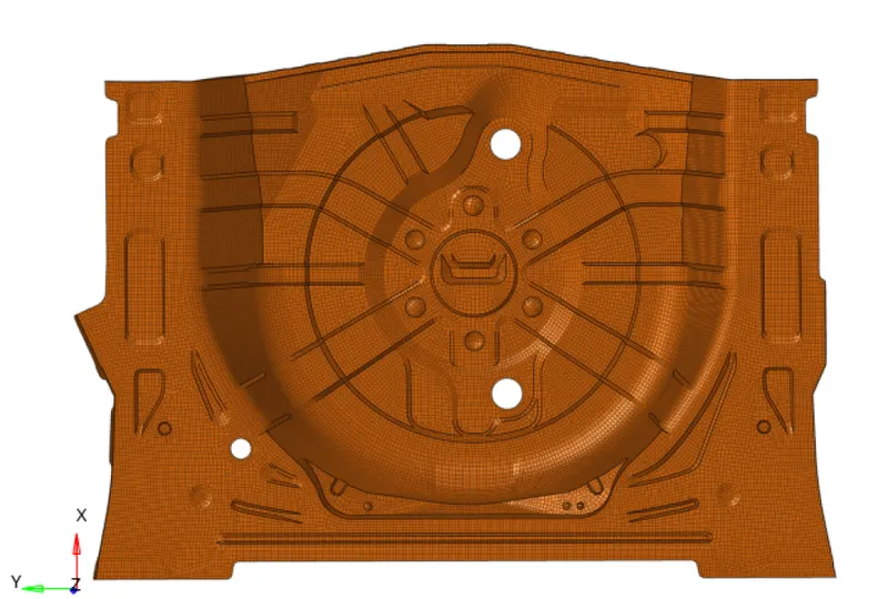
Then the elements were checked for quality criteria. All the failing elements were fixed by remeshing and using element optimization tools like element cleanup, node optimization, edit element, drag tria element, smooth, etc. Elements failing for minimum element length in tight/converging regions were fixed by translating the node slightly off the geometry. The image below shows the final mesh created,
Finally, material is created by 'right click>create>material' in the model tree viewer. And named as 'Steel'. Similarly, a property is created by 'right click>create>property' and under parameters, thickness value is configured to 0.75mm. Both are then assigned to the mid surface component.
Conclusion:
2D shell mesh was successfully generated for the floor panel model with no element failing according to the quality criteria. Trias concentration was also kept low at 2.7%. Finally, the elements were checked for connectivity issues and no connectivity issue was found.