Structural Meshing of the Car Spare Wheel Holder using Hypermesh
Structural Meshing of the Car Spare Wheel Holder using Hypermesh
- Introduction
In this project, we will perform pre-processing of car spare wheel holder. Modeling of the same component is to be done by extracting mid surface and meshing the component by achieving all the mentioned quality criteria parameters.
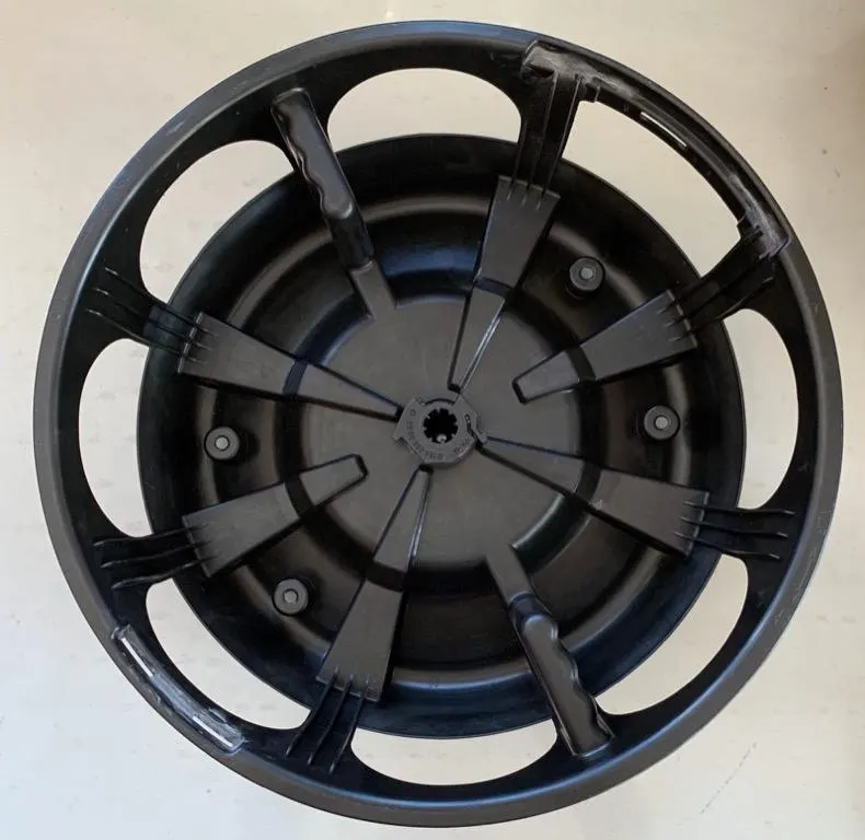
The spare wheel holder in a car plays a vital role in providing a housing for the spare wheel, jacks and all the necessary tools required.
The spare wheel holder should be able to avoid the unnecessary space occupied by the spare wheel in the storage portion of the car.
To perform analysis in the model, the model must be properly discretized into finite number of elements within the quality criteria in such a way that, the model is ready for analysis.
AIM
To perform pre-processing of car spare wheel holder for structural analysis. Steps involved in pre-processing are,
1. Inspect the CAD Geometry and Clean the model
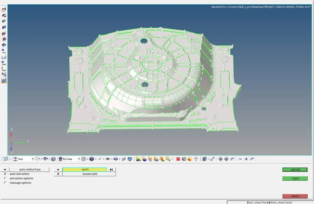
2. Extract Mid surface by using various techniques for sheet metal components
3. Performing the 2D mesh on the Mid Surface
4. Solving failed elements by various Mesh improvement tools
5. Conversion of 2D- shell elements to 3D solid Elements
PROCEDURE
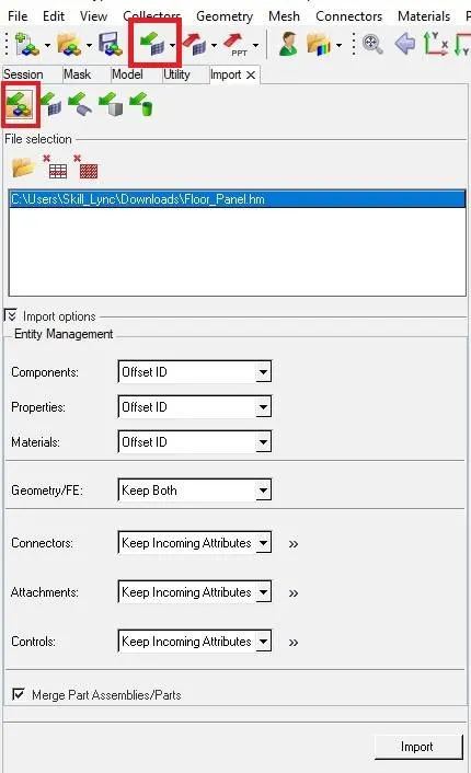
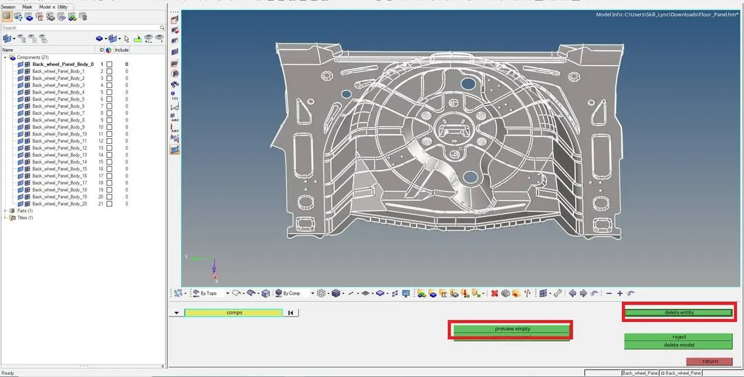
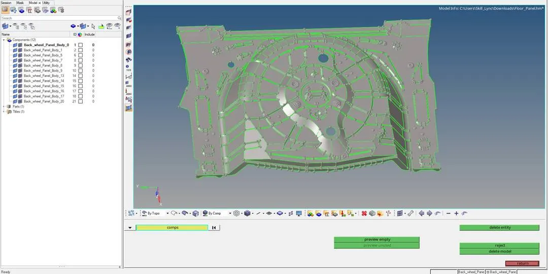
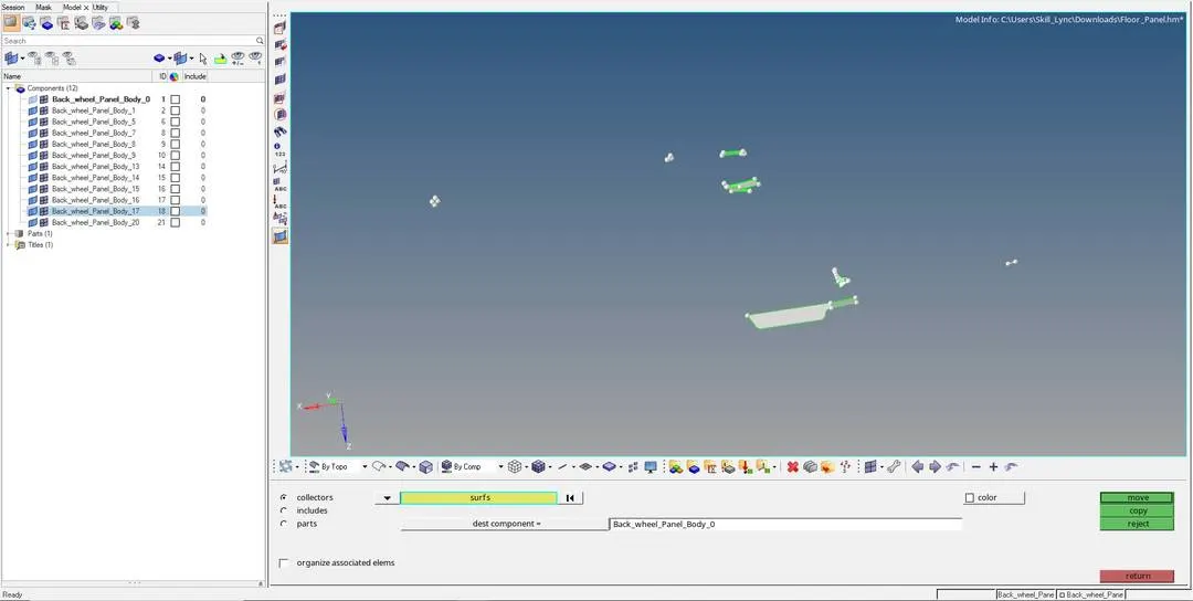
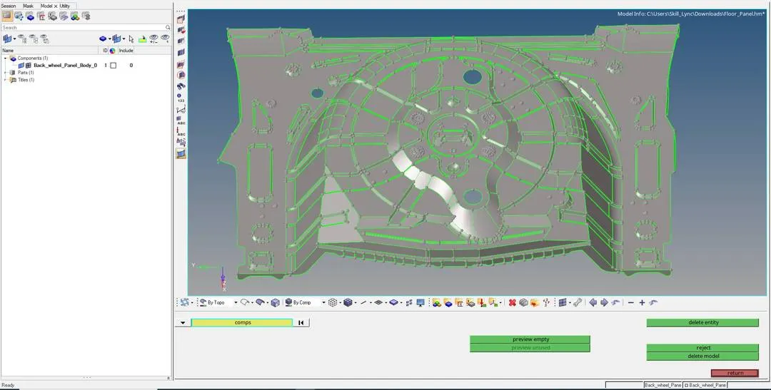
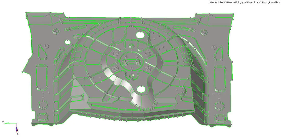
1) Import the model using, Import solver deck -> Import model option.
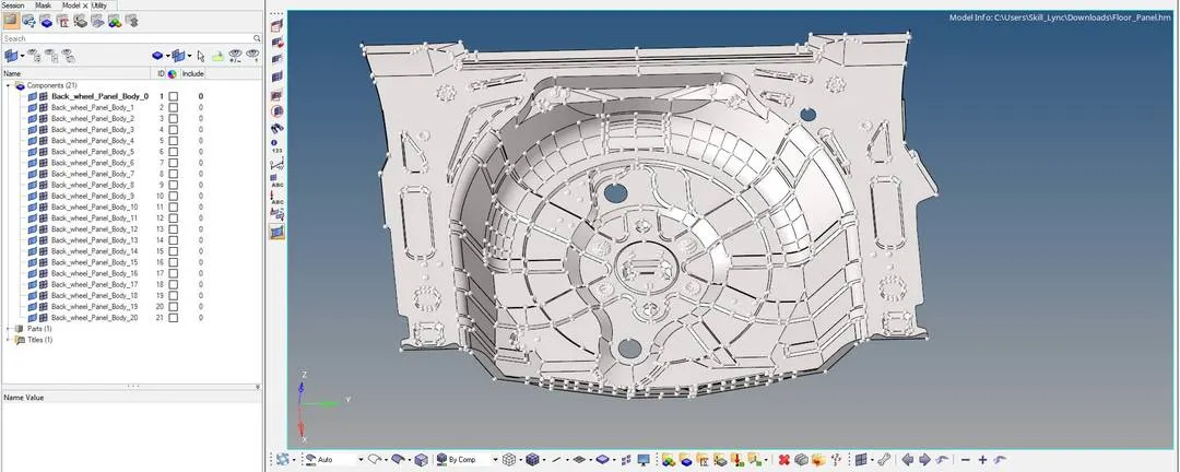
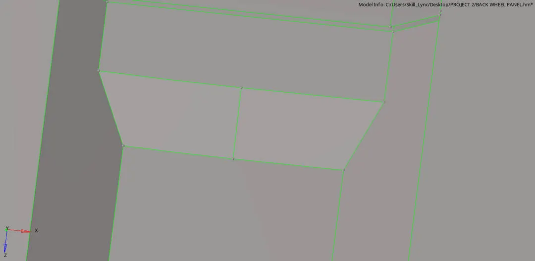
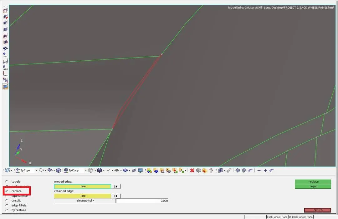
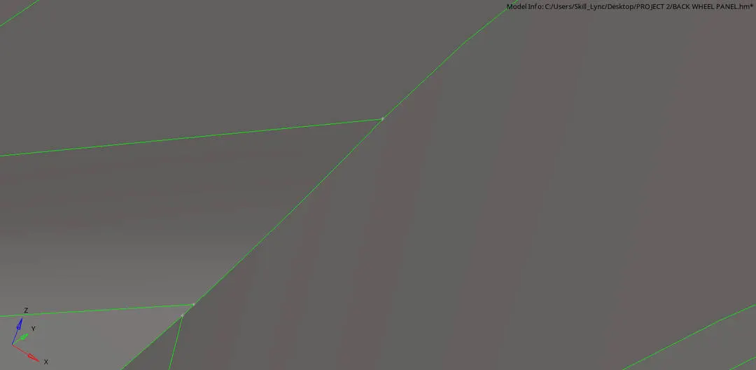
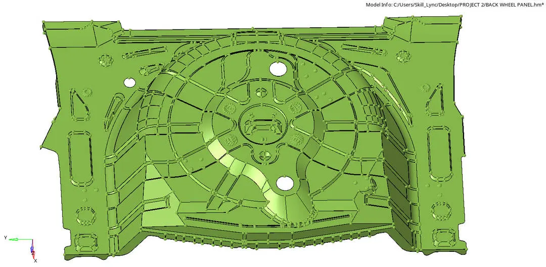
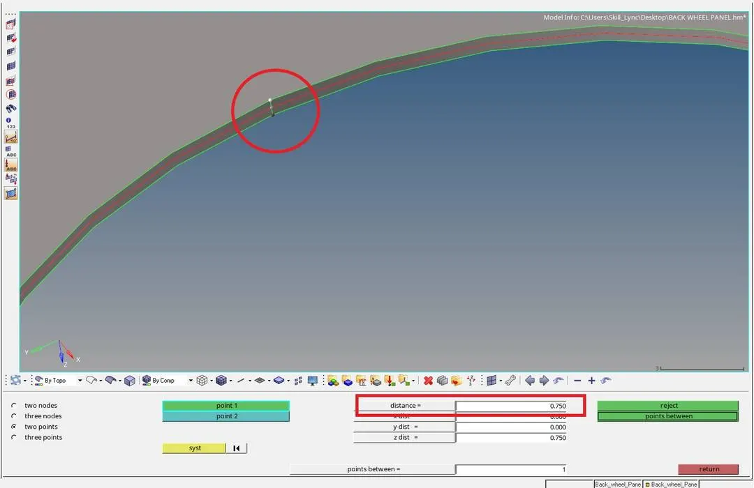
- Measure the thickness of the Model
To measure the thickness of the model goto, Geometry -> distance -> 2 points, pick 2 points to measure. as shown in figure below model as a uniform thickness of 0.75 mm.


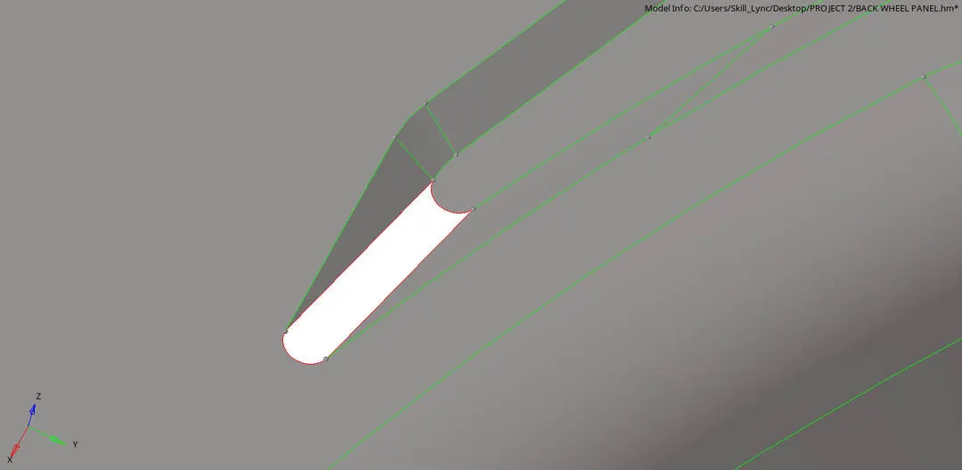
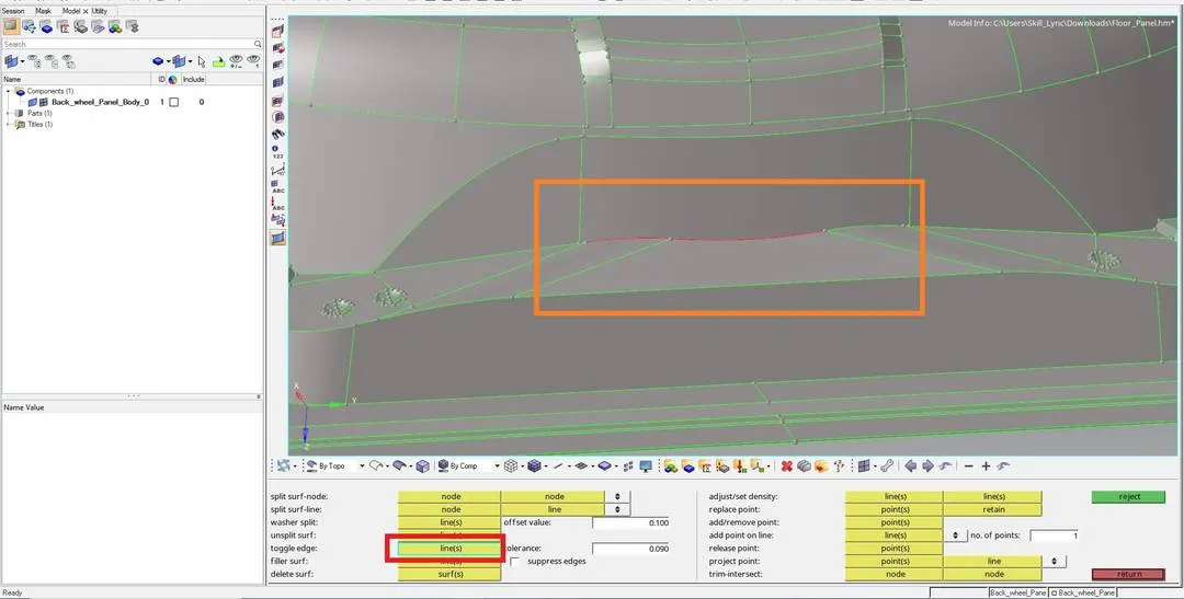
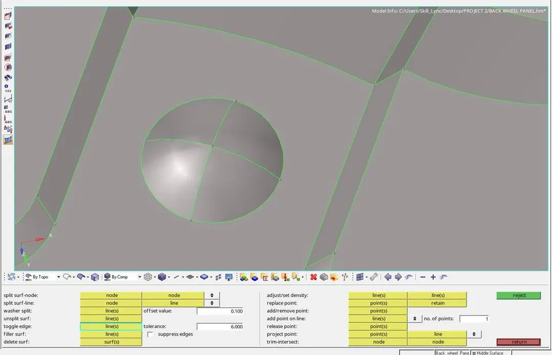
( a) Geometry -> Quick edit -> Filler surfaces, and select the free edge


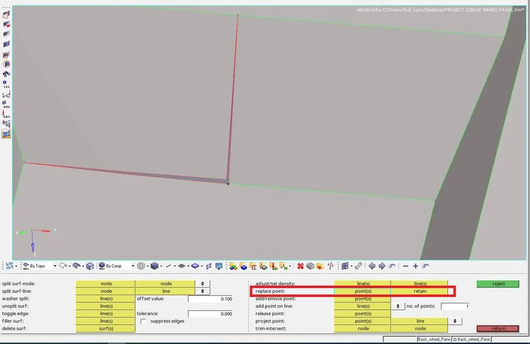
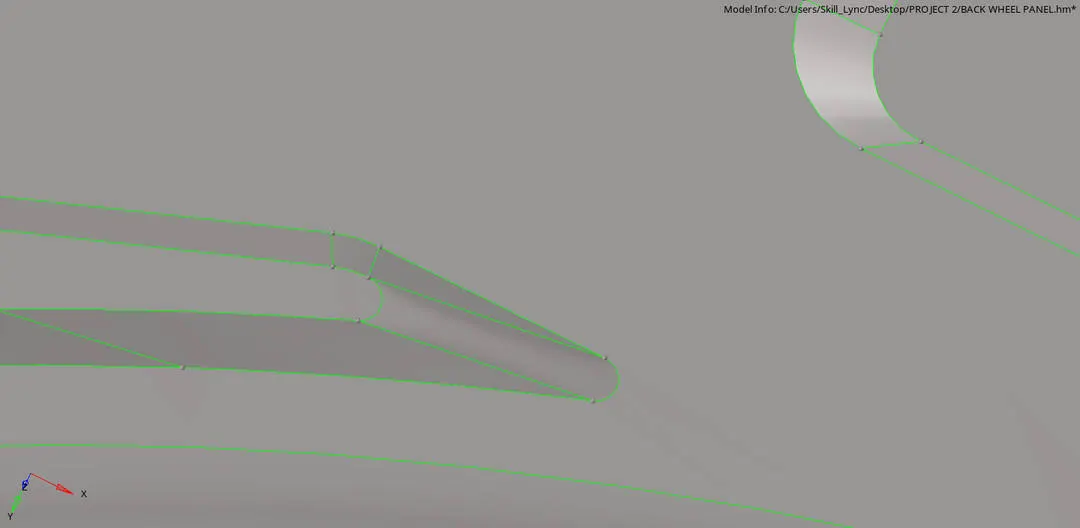
(b) go to Geometry -> Surfaces -> Ruled surfaces, select the first and second line lists and click create.


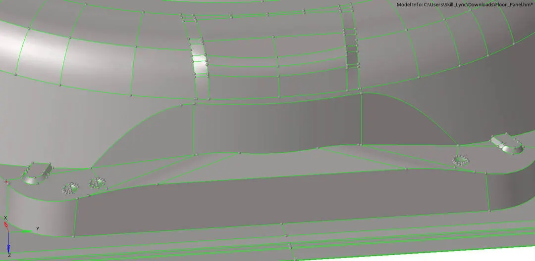
after fixing errors in mid-surface

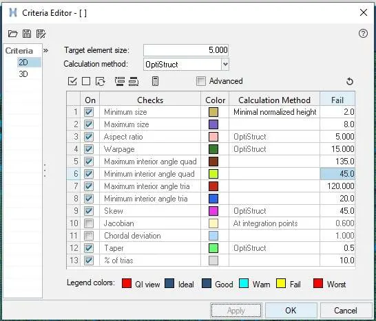
First we need to enter the element quality criteria, go to Preferences -> Criteria file settings and enter the values.
Figure below shows the element quality parameters given for the model.
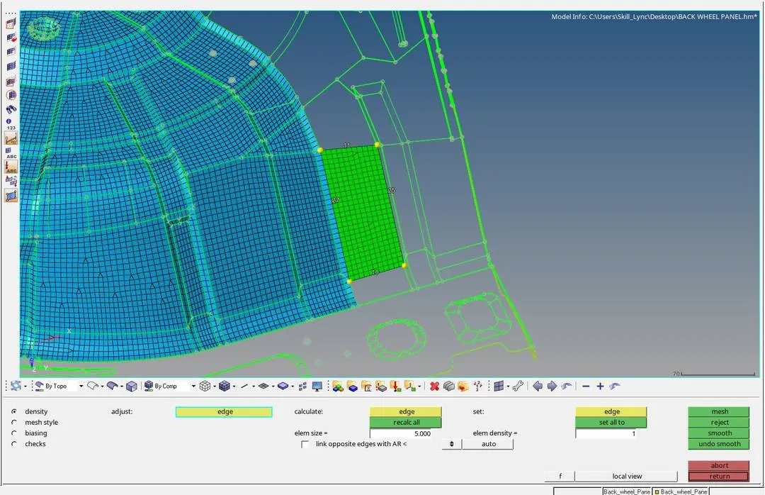
To create a mesh on the mid-surface, go to 2D -> Automesh -> select the surface and choose the element size as 5 and select type of elements -> click mesh

we can change the element density by increasing or decreasing the number of nodes, left mouse click to increase and right mouse click to decrease.
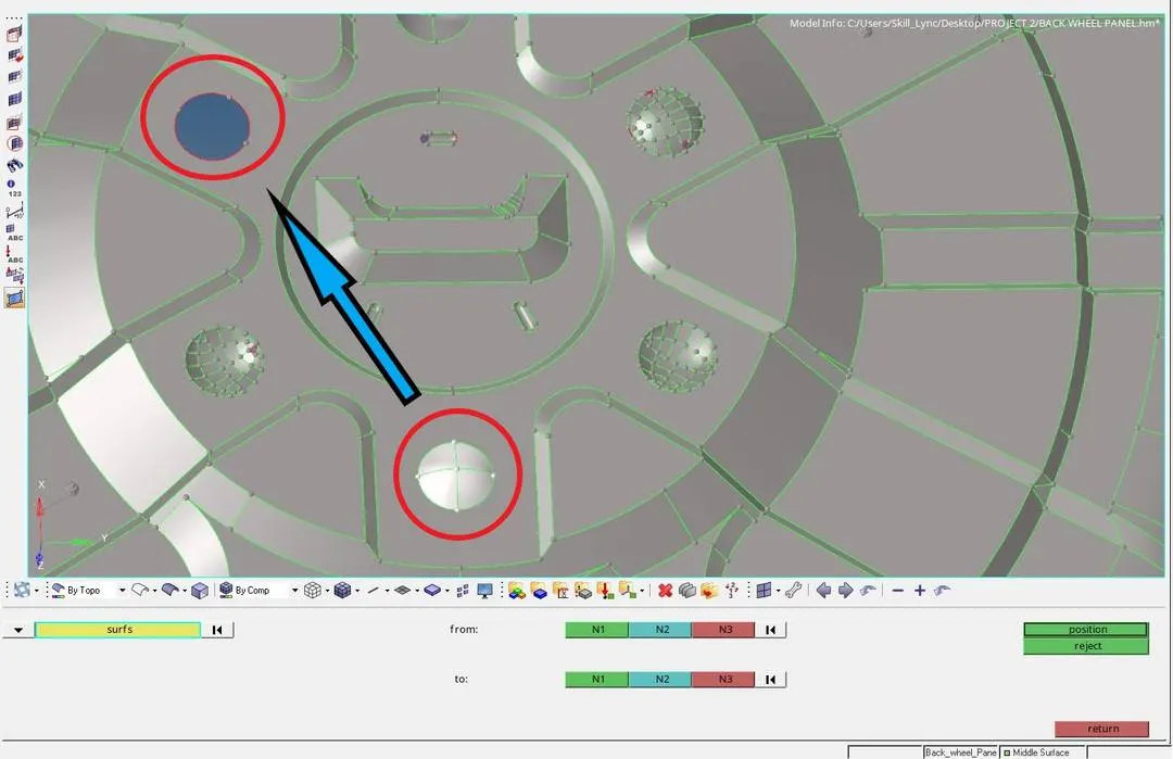
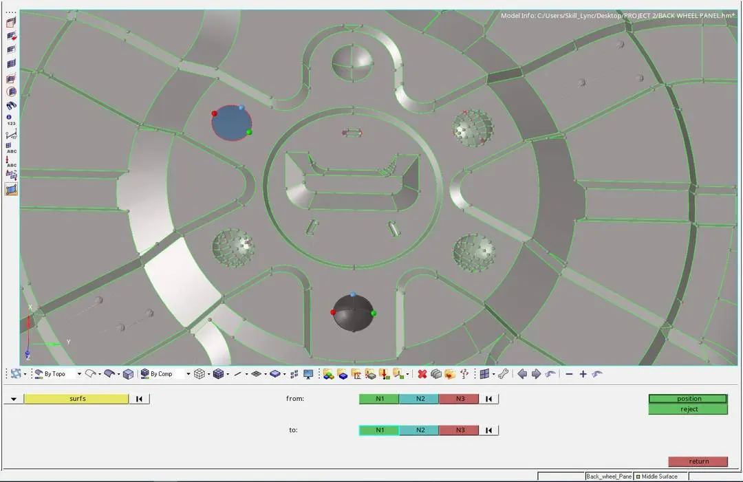
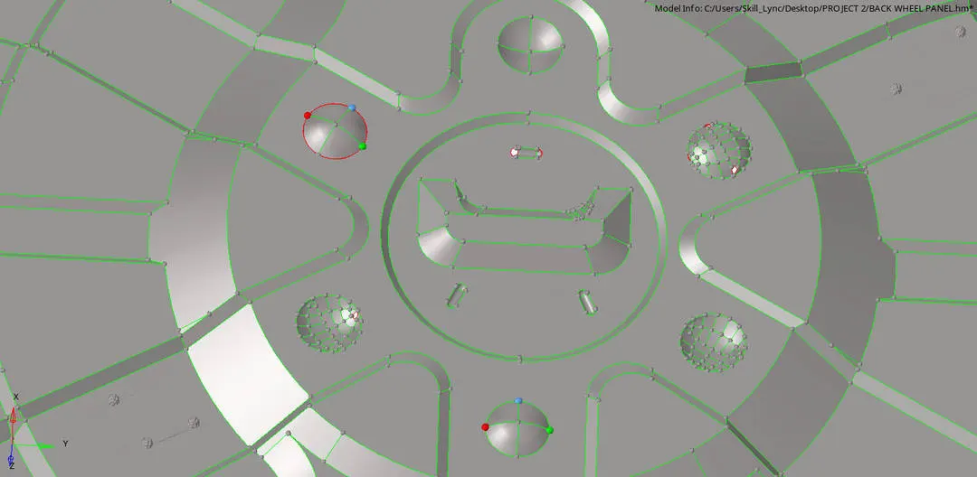
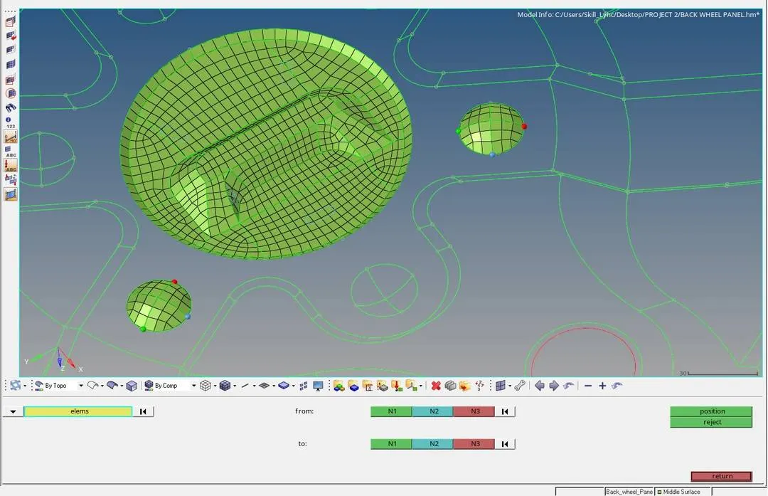
we can also use Tools -> Position tool to position element from one feature to another, select elements in one feature then select nodes N1, N2, N3
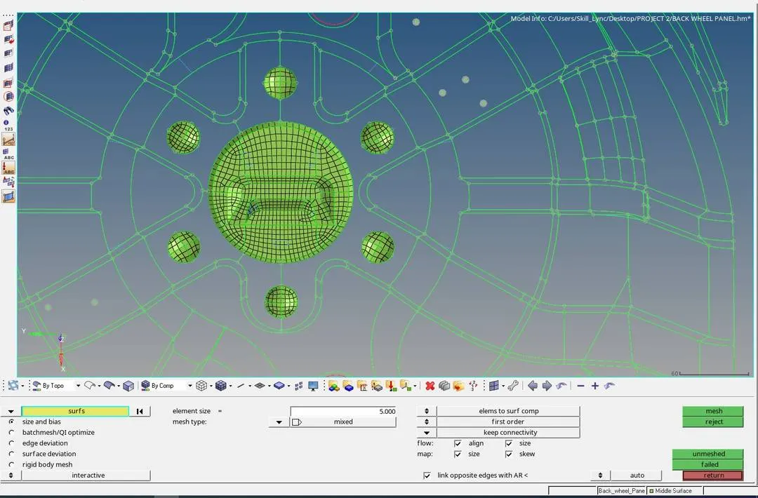
After positioning elements to all the features
Handling of Tria Elements
Tria elements are the elements formed with 3 nodes. There are certain rules considered while handling Tria elements.
When it comes to Tria elements, there are a few thumb rules to be followed
-
The Tria elements should never be opposite to each other
-
No Tria elements should be connected back to back
-
No Tria elements should be on the edge of the geometry
-
No Tria elements should be near the holes
-
No Tria elements should be on the feature and the fillets.
-
There should be less Tria concentration, i.e., there should be a considerable distance between Tria elements.
The reason for such care for the Tria element is because of their stiffness. When the load is applied and if the stress concentration areas like the fillets, holes are modeled with Trias then the results will not be accurate because of the Tria stiffness. This is also a reason why the holes which are in the stress concentration region are modeled with a washer i.e, a few layers of quads to extract an accurate result.
Here are a few examples of Tria that we have to avoid.
In order do the tria management, go to 2D -> quality index -> cleanup tools,

you can use drag tria element tool to drag and combine opposite tria elements ,also we can use swap edge tool to swap tria from free edges.

5) Solving failed elements by various Mesh improvement tools
To clear Element failures we can use smooth option in clean-up tools. ( 2D -> quality index -> Cleanup tools )

Skewness:
Skewness is the quality of the elements in terms of angles. For a Quad element,
In case of an ideal quad.
Whereas, when you have a distorted quad,
For this quad when we calculate the skewness it will be 45deg.
Fix:
Now let see how this skewness is calculated in a Tria element. Here the angle between the meridian line and the mid node line is calculated.
The angle between the meridian and mid node line is 90, when calculated for skew it becomes 0deg.
Let us also check for the distorted tria,
The minimum angle here is 35, if we calculate the skewness it becomes 55.The ideal value of Skew is 0deg but considering the geometrical constraints and accuracy needed, we can have a tolerance to this criteria.
Fix:
To get rid of this skewness in the element, you can re-mesh the elements or you can manually move the nodes to increase the angle.
Figure below shows element failing for skewness
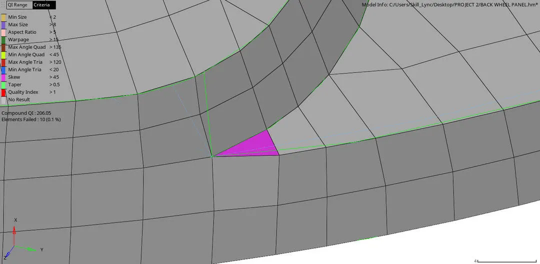
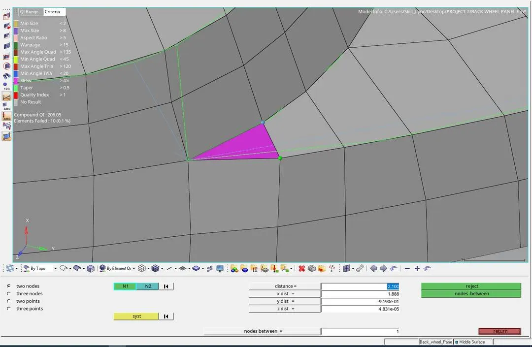
In order to clear Skewness element failure, we need to increase the distance between nodes manually, go to Geometry -> Distance -> select nodes, and enter distance value. as shown in figure below.
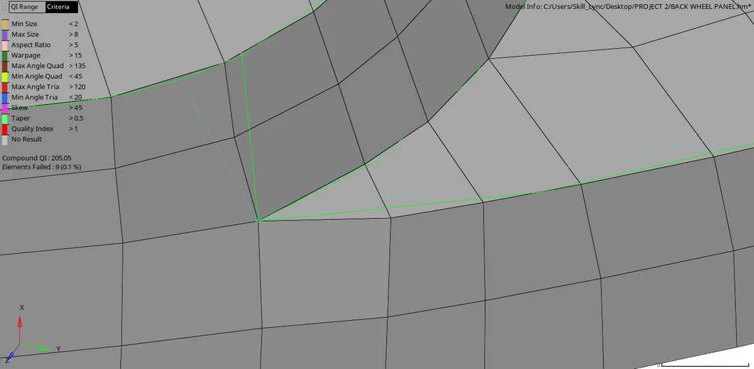
After clearing skewness failure
Warpage:
Whenever you have a quad element in two different planes then you will have your element failing for Warpage. Ideally, your element should be in a single plane, when they are in two different planes if you split the quad along the diagonal and measure the angle between the normals it will give your element Warp angle. Warp angle is the angle of plane deviation in your element which is also known as Warpage.
figure below shows element failing for warpage
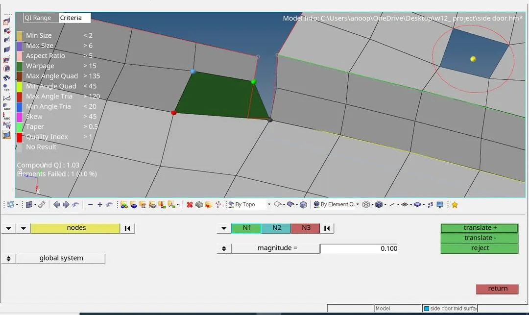
In order to fix warpage you can move the nodes in the normal direction so that they stay in the same plane where the other nodes are, else you can split the element and have Trias. The Tria element will not have Warpage as they form in one plane.
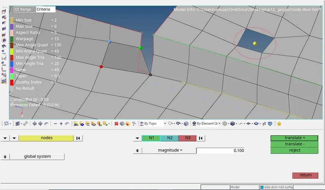
To move the nodes of element, go to Tools -> Translate -> select the node to move and select the plane by choosing nodes N1, N2, N3. then click on translate +/- with respect to the direction we need to move the node to clear the warpage failure.
Reflecting the Mesh
we can reflect mesh to the symmetric portion of the model using Tools -> Relfect option.
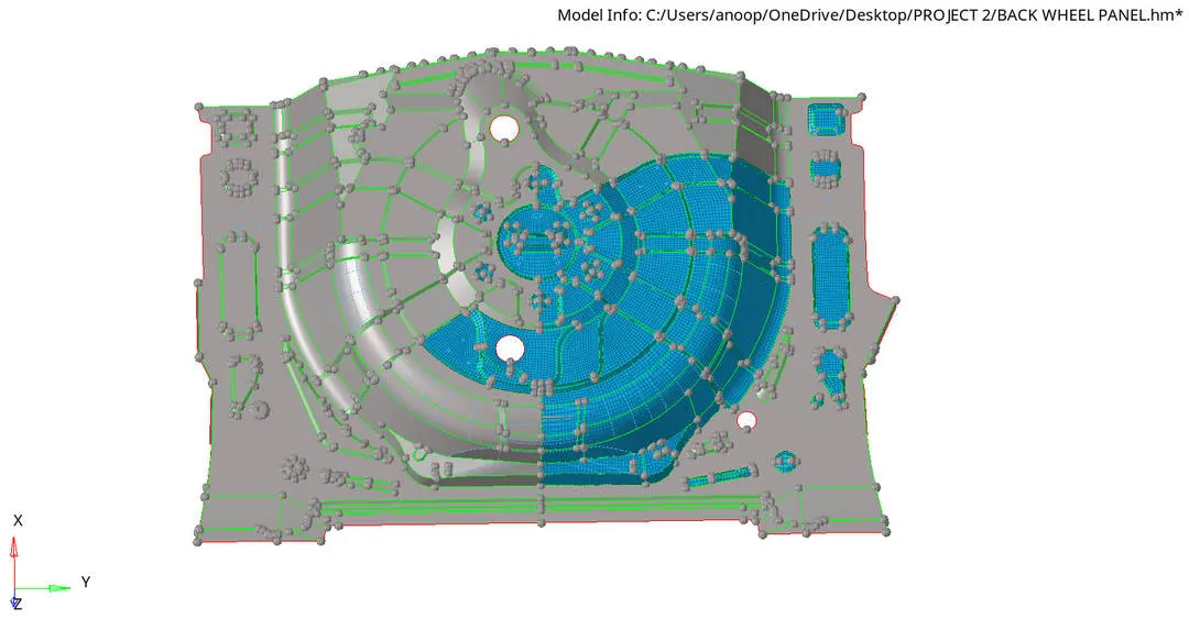
select elements to reflect and duplicate the elements to the current component then choose the axis and base point for reflection as shown in figure below.
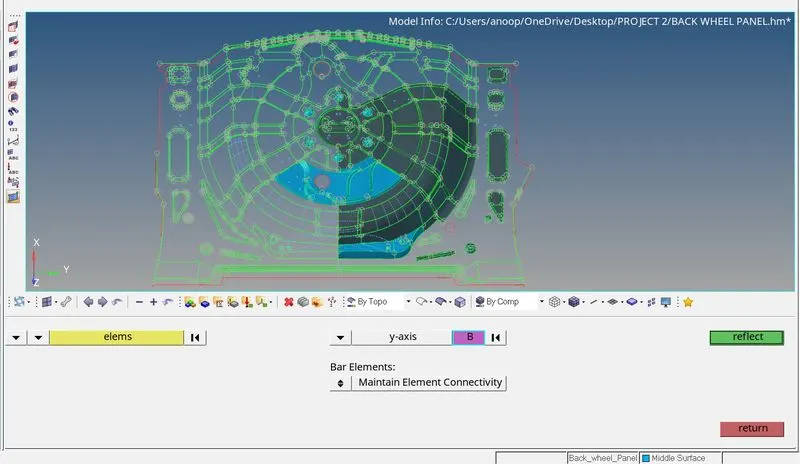
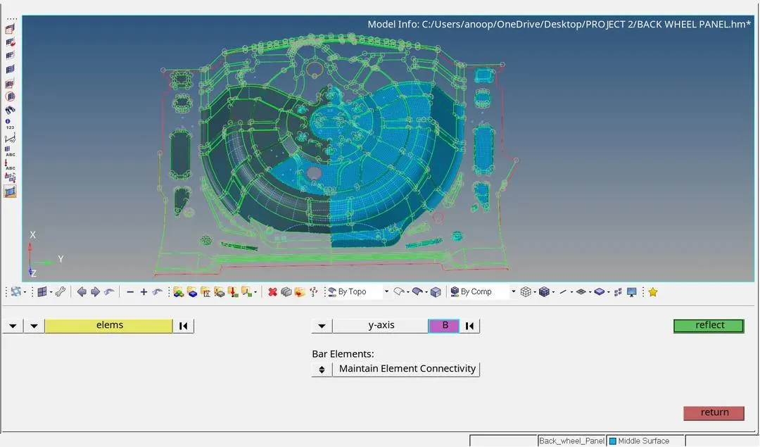
After Reflection
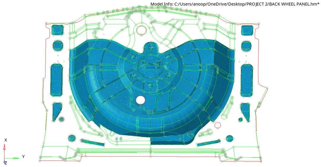
To align misaligned nodes to the feature line
Figure below shows nodes are misaligned from the feature line,
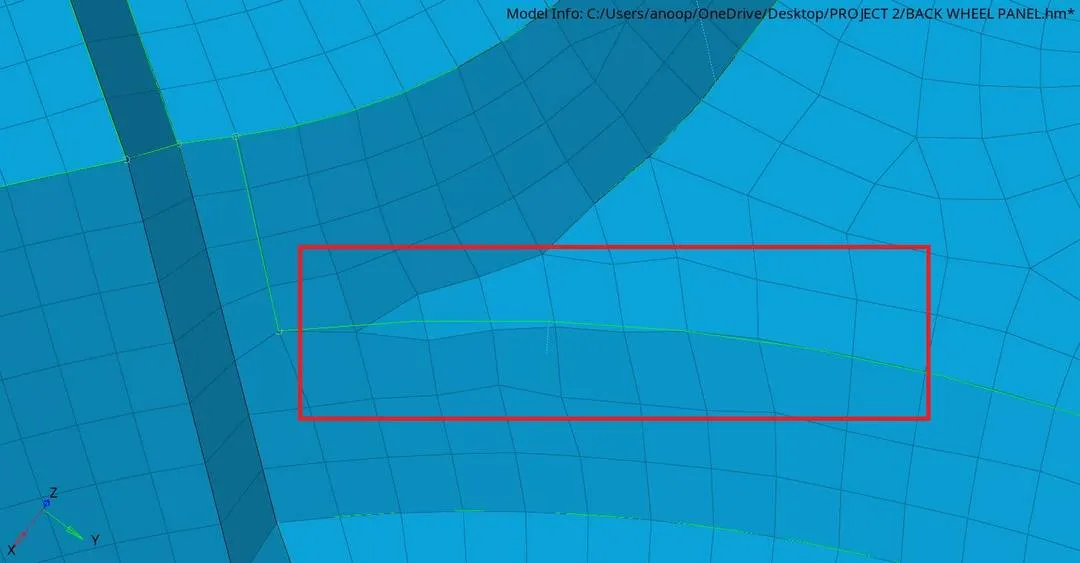
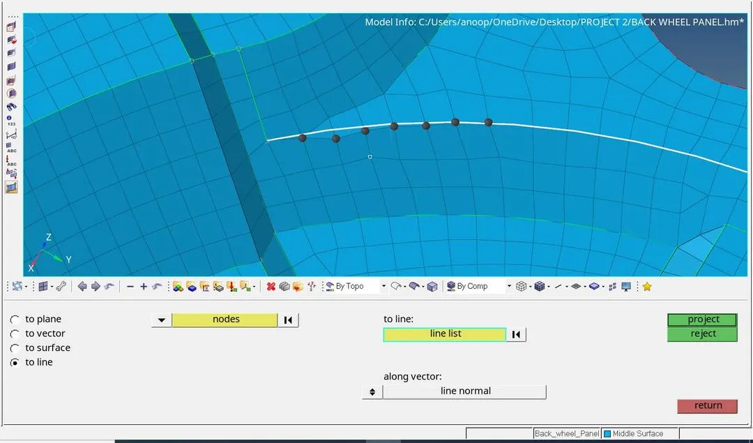
In order to place the nodes to the feature line, use Tools -> Project tool, select the misaligned nodes , choose to line and select the feature line and click project.
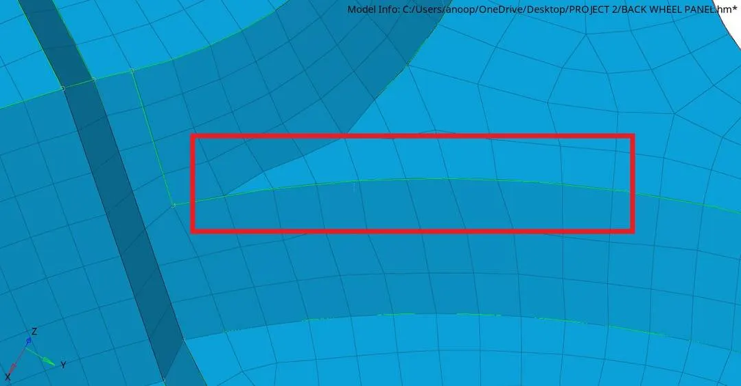
After aligning nodes to the feature line
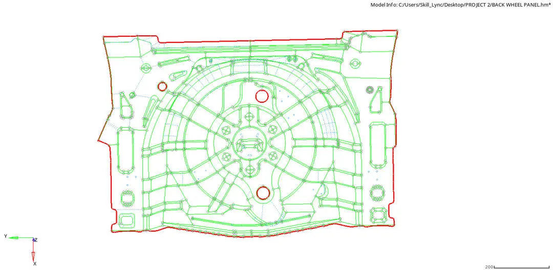
Checking for free edges in the model
Go to Tools -> edges -> select all elements -> find eges ,
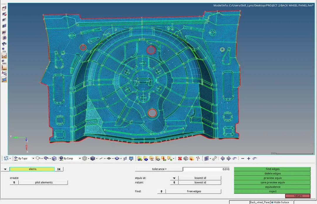
figure below shows there is proper connectivity between elements, there are no free edges present in between elements.
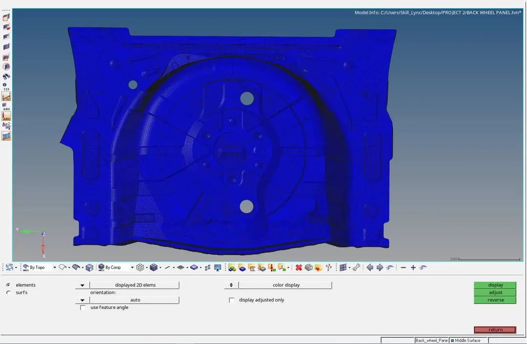
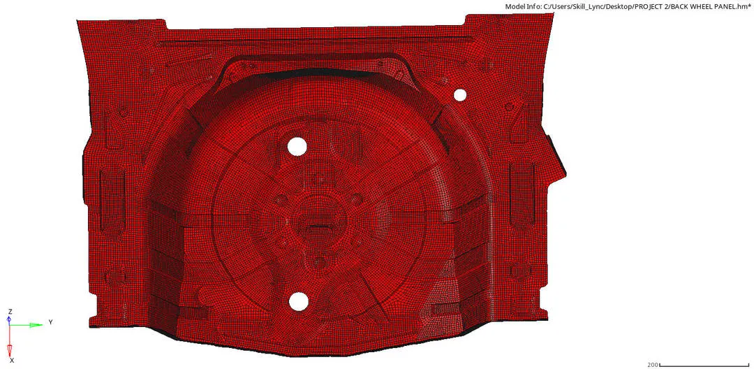
Checking for normals of elements
Go to Tools -> Normals -> select all 2D elements -> click display
6) Conversion of 2D- shell elements to 3D solid Elements
In order to convert 2D shell elements in to 3D solid elements we need to assign thickness to the shell elements.
right-click -> create -> property -> create a new property and input thickness value as 0.75 mm. then assign the property to the meshed mid-surface of back wheel holder.
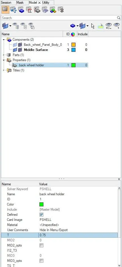
Thickness representation
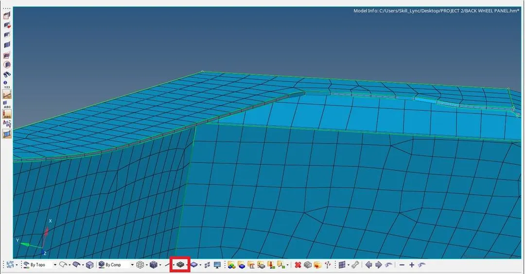
In order to see thickness assigned switch on 2D detailed element representation as highlighted in the figure below
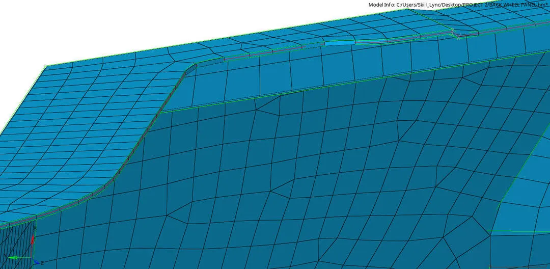
Result
Performed structural 2D Meshing of car spare wheel holder under given element quality criteria and assigned thickness to the shell elements. steps carried out in this project are,
1. Inspect the CAD Geometry and Clean the model
2. Extract Mid surface by using various techniques for sheet metal components
3. Performing the 2D mesh on the Mid Surface
4. Solving failed elements by various Mesh improvement tools
5. Conversion of 2D- shell elements to 3D solid Elements
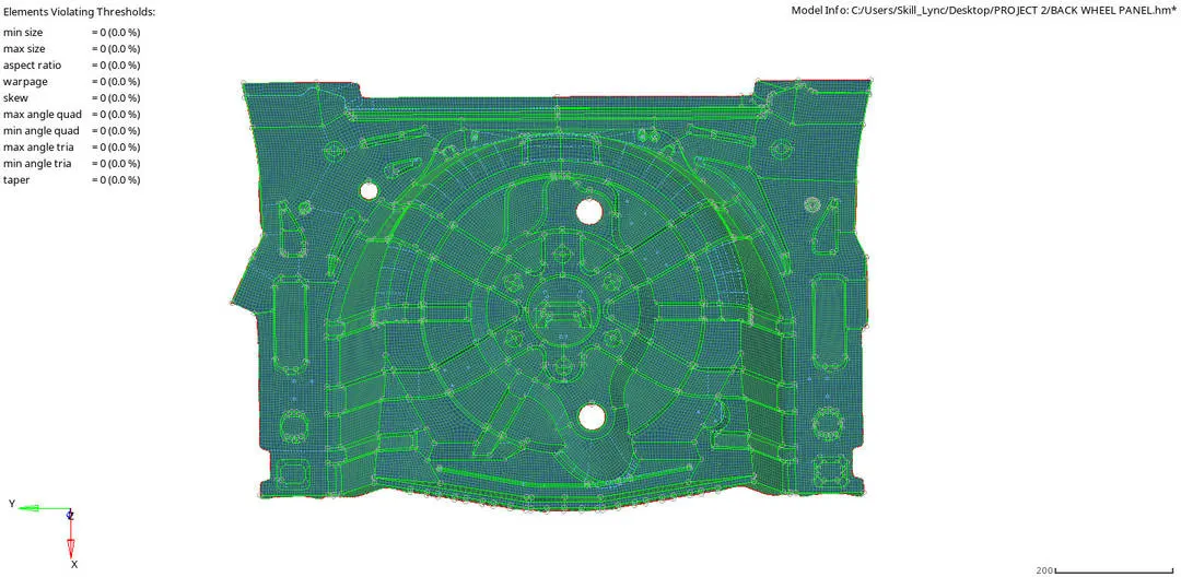
Final image of Meshed Car spare wheel holder
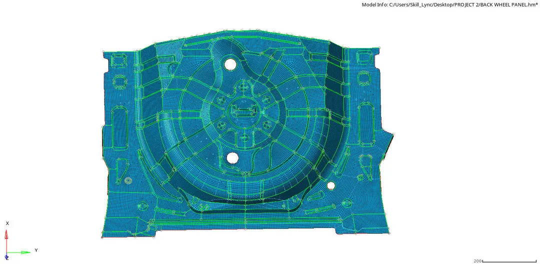
Final image After clearing element quality failures