Project 2 - 3D CFD modelling of Air cooling system and liquid cooling system for battery thermal management
Problem Statement
- Comparative study of thermal performance of air-cooled and liquid-cooled battery modules.
- Module consists of 5 prismatic cells enclosed in an aluminum enclosure
- Worst case scenario- cell soaked at 45⁰C ambient with heat generation corresponding to 0.5 C discharge
- Inlet temperature of 20 ⁰C for both air and liquid
A Battery Thermal Management System (BTMS) is essential to:
- Maintain battery cell temperature within the optimal range (usually 20–40°C)
- Prevent thermal runaway
- Enhance battery performance, efficiency, and lifespan
Two common BTMS types are air cooling and liquid cooling.
Air Cooling System
Principle:
Air is used as the heat transfer medium to remove heat from battery cells by forced convection.
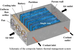
Key Equations:
Convection Heat Transfer:
Q=hA(Tcell−Tair)
where:
- Q = heat removed (W)
- h = convective heat transfer coefficient (W/m²·K)
- A = surface area of the battery
- Tcell , Tair = temperatures of the cell and air
Characteristics:
- Simpler and lower-cost design
- Lower heat transfer efficiency
- Requires high airflow rate
- Limited cooling for high power batteries
- Susceptible to ambient conditions
Liquid Cooling System
Principle:
Liquid coolant (e.g., water, glycol) circulates through embedded channels or pipes to absorb heat from battery cells via conduction and convection.
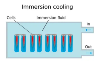
Key Equations:
Conduction inside battery pack:
Q=(kA(Tcore−Tsurface)) / d
where:
- k = thermal conductivity
- d= thickness
Convection in coolant channel:
Q=m * cp(Tout−Tin)
where:
- m = mass flow rate (kg/s)
- cp = specific heat of coolant
Characteristics:
- Higher heat transfer rate due to liquid's higher specific heat
- Compact and more effective for high energy/power density batteries
- Higher design complexity and cost
- Requires sealing and pumping system
Comparison :
| Parameter | Air Cooling | Liquid Cooling |
|---|---|---|
| Heat removal efficiency | Low | High |
| Cooling uniformity | Poor | Better |
| Complexity | Low | Medium to High |
| Cost | Low | High |
| Mass flow required | High | Low |
Project Objective
- To model and simulate air-cooled and liquid-cooled BTMS using ANSYS Fluent.
- To evaluate the thermal performance of each system under a worst-case ambient temperature of 45°C.
- To compare temperature profiles, heat removal efficiency, and fluid outlet temperatures.
Battery Module Specifications
- Number of Cells: 5 prismatic lithium-ion cells
- Enclosure: Aluminum
- Heat Generation: 1188 W/m³ (calculated for 0.5C discharge)
- Inlet Coolant/Air Temperature: 20°C
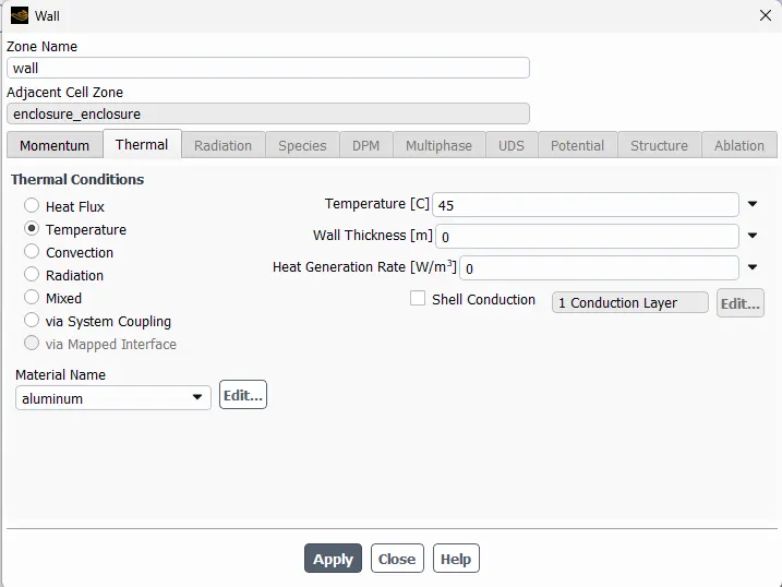
- Ambient Temperature: 45°C
Simulation Setup
Geometry: 3D model of battery module and airflow domain
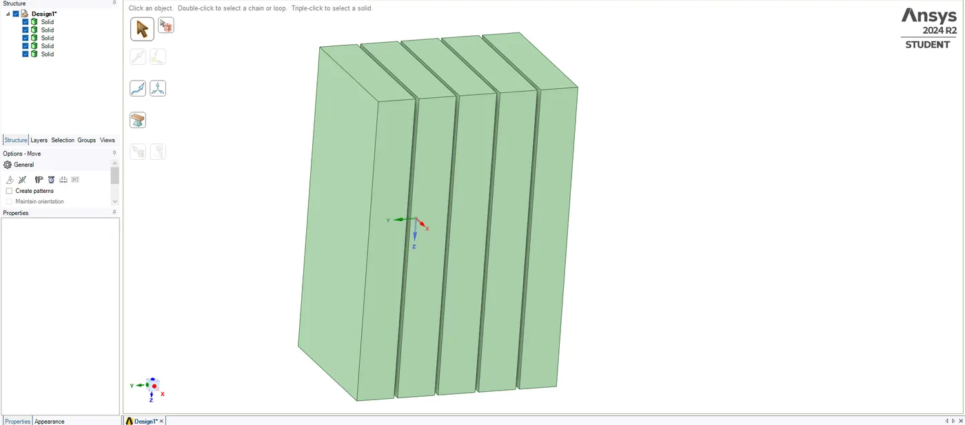
Alluminium Enclosure:
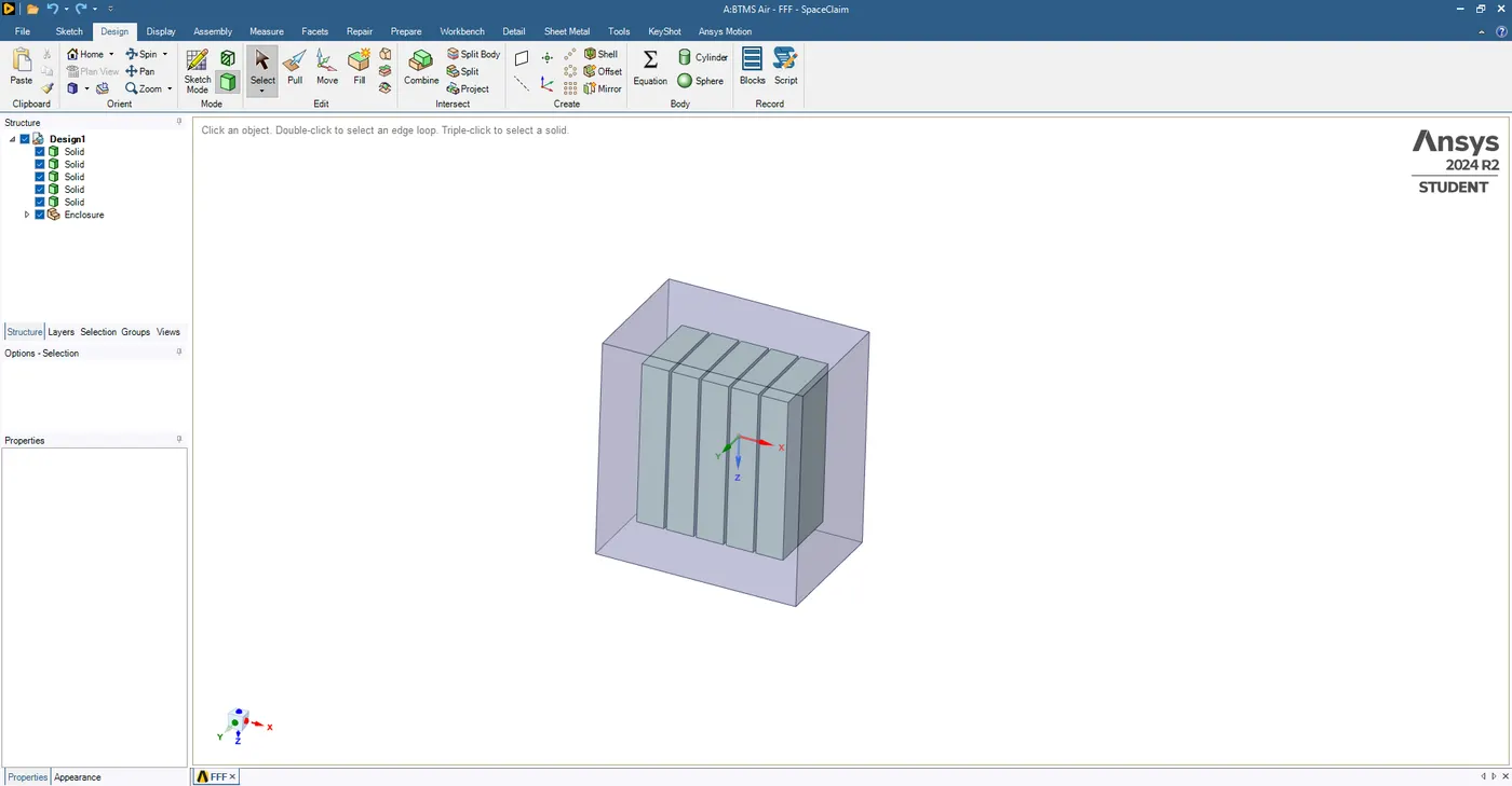
Mesh: Hex-dominant with boundary layers
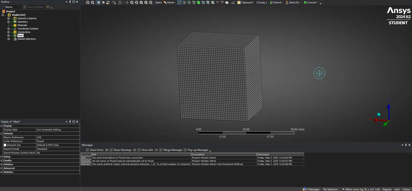
Named Selections :

1)Air cooling System
Fluid: Air (Ideal Gas)
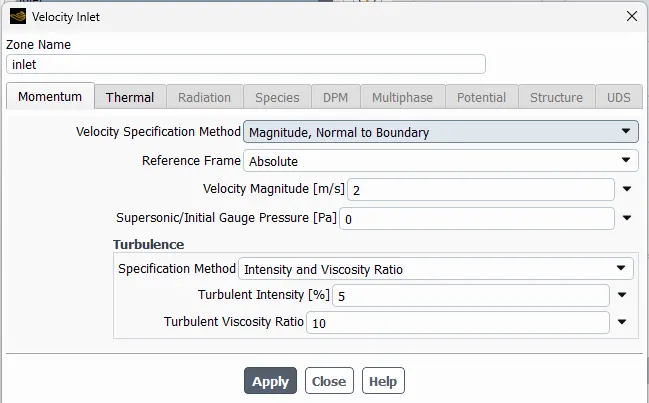
Inlet: Velocity Inlet (2 m/s), Temperature = 20°C
Outlet: Pressure Outlet (0 Pa)
Energy Equation: Enabled
Viscous Model: k-epsilon
Heat Source: Applied to each cell as volumetric generation
Discharge Current
I=0.5*50=25 A
Heat Generated per Cell
Q = I2*R = 252*0.002 = 625*0.002=1.25 W
Volumetric Heat Generation (W/m³)
q = Q/Volume = 1.250 / 001053 ≈ 1187.9 W/m3.
Materials :
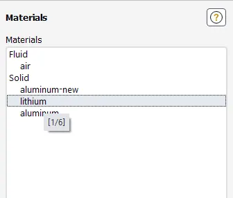
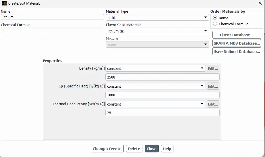
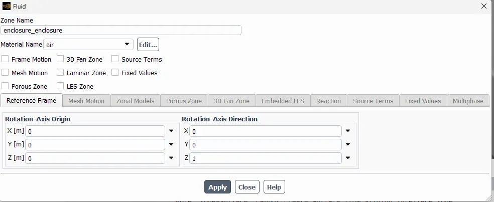
Cell Zone Conditions :
For cells :
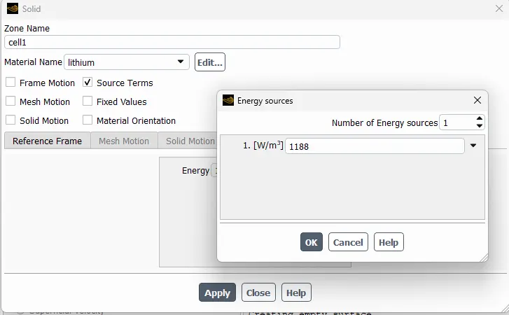
For enclosure : Air cooling
Boundary Conditions :
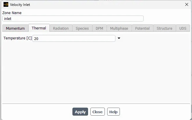
Wall ambient temperature with worsen condition :
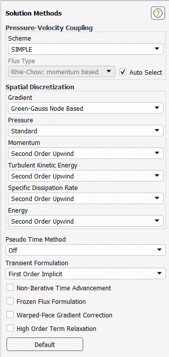
Solution Methods :
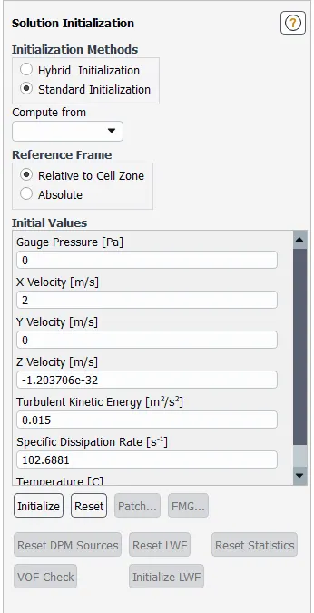
Solution Initialization :
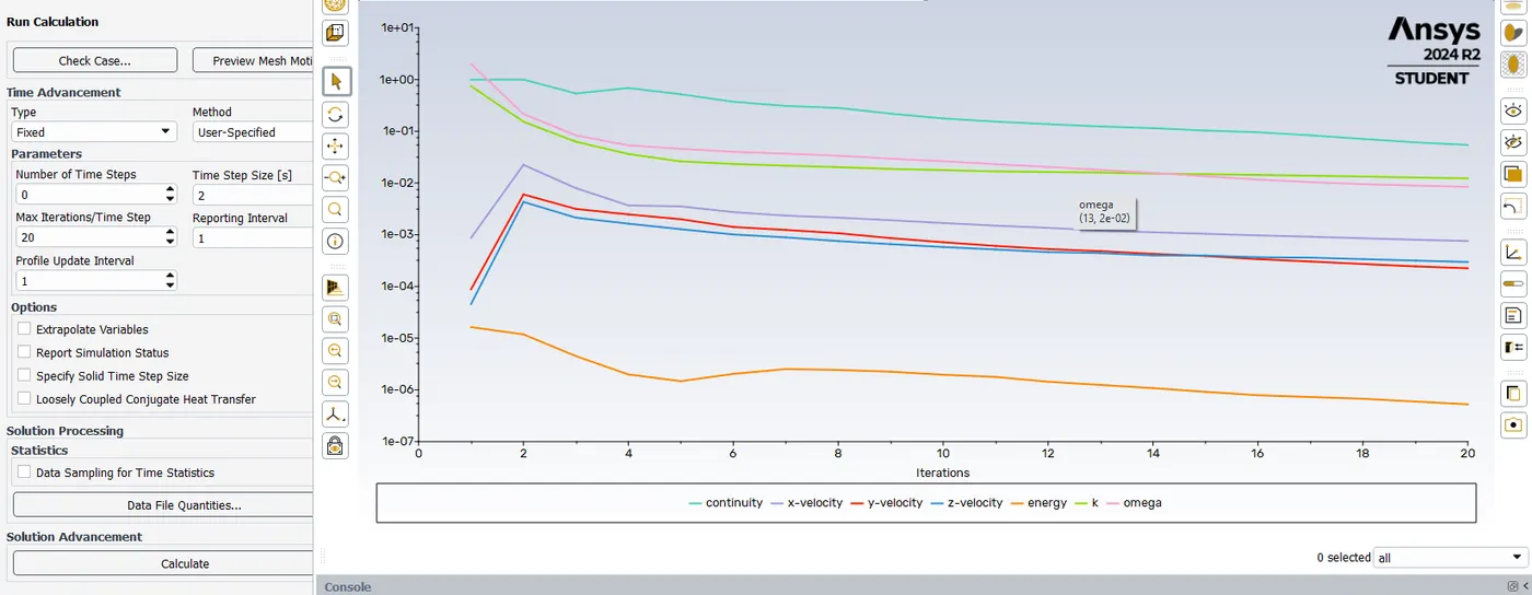
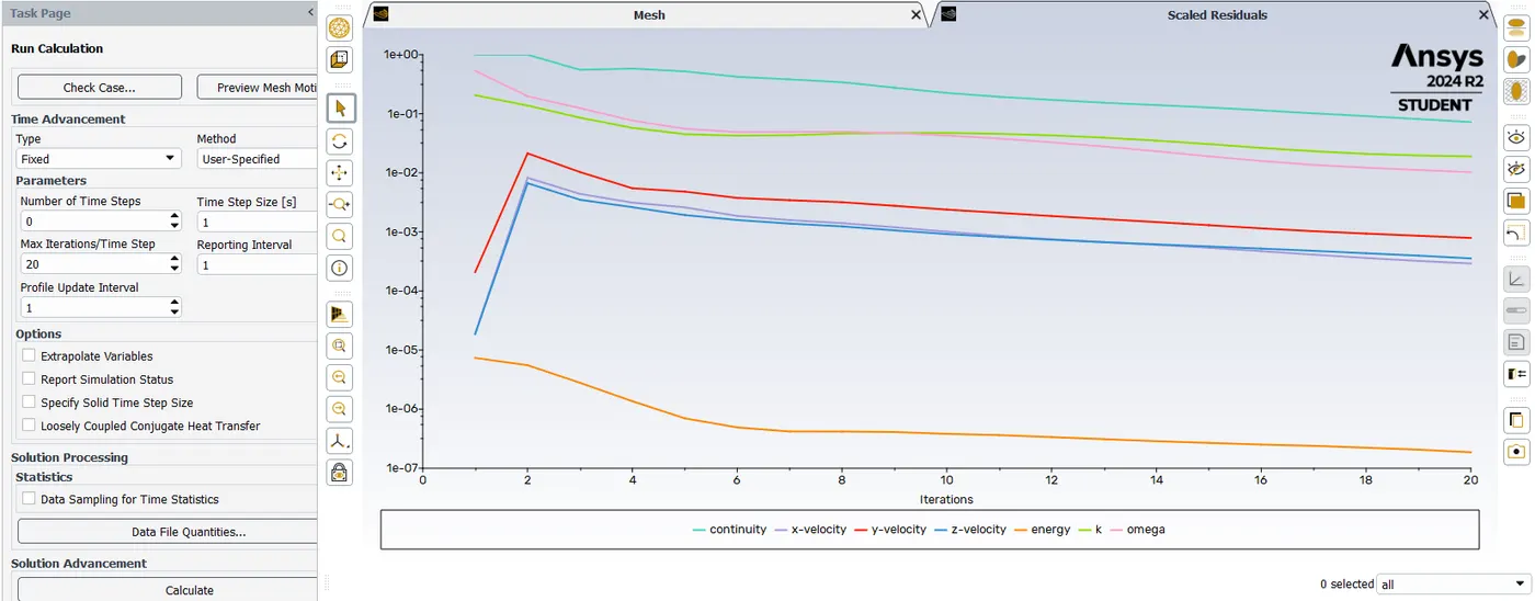
Calculation Running :
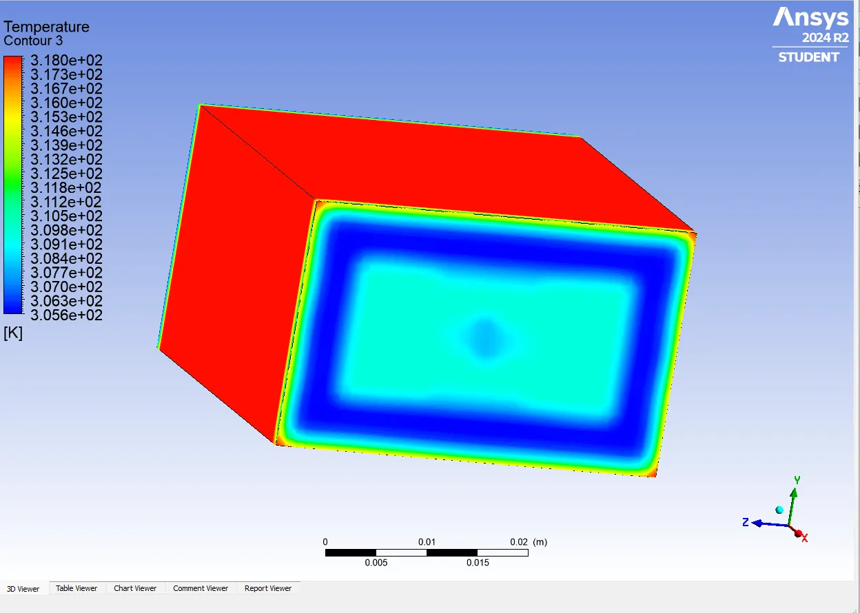
Results :
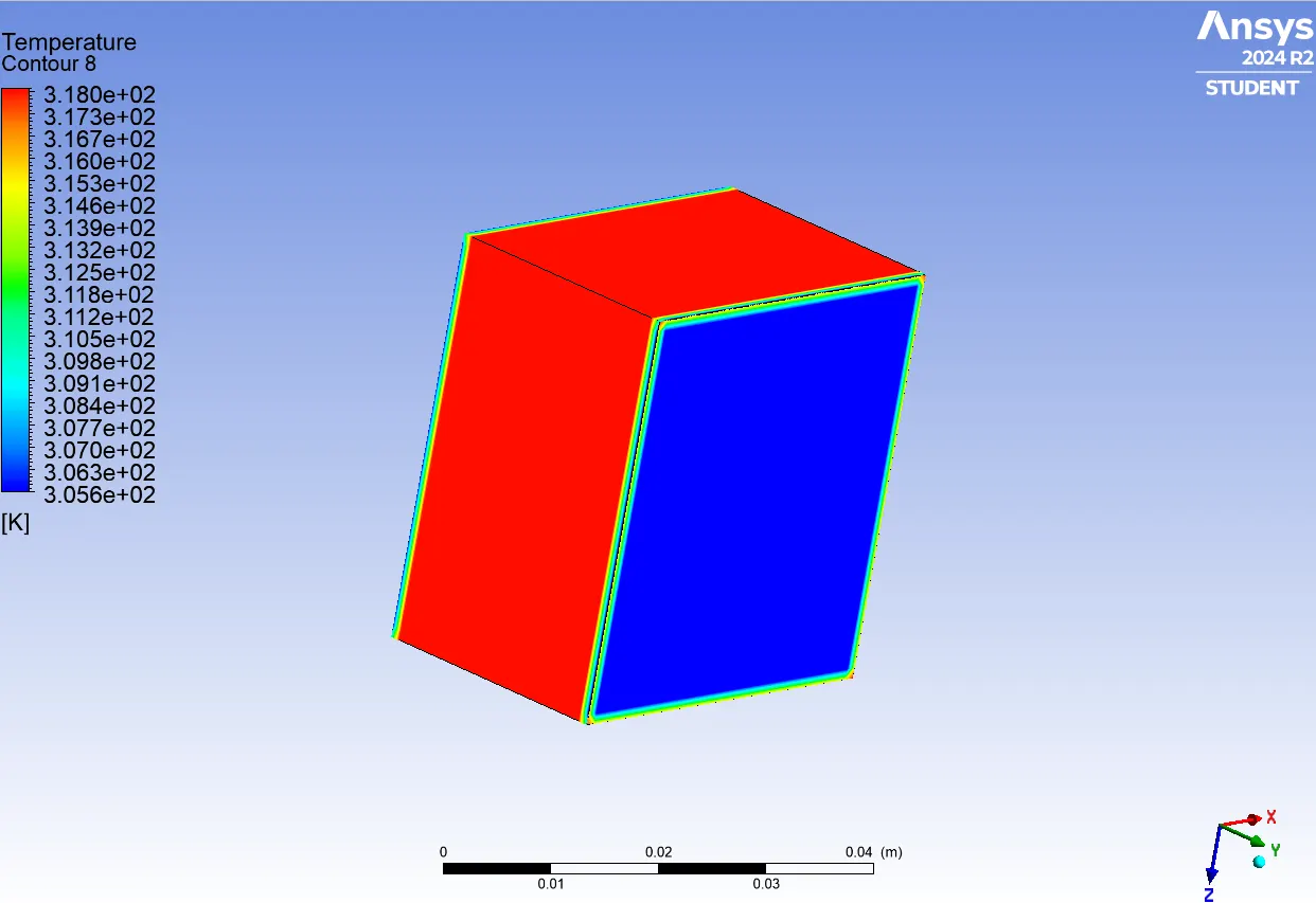
Temperature on Wall
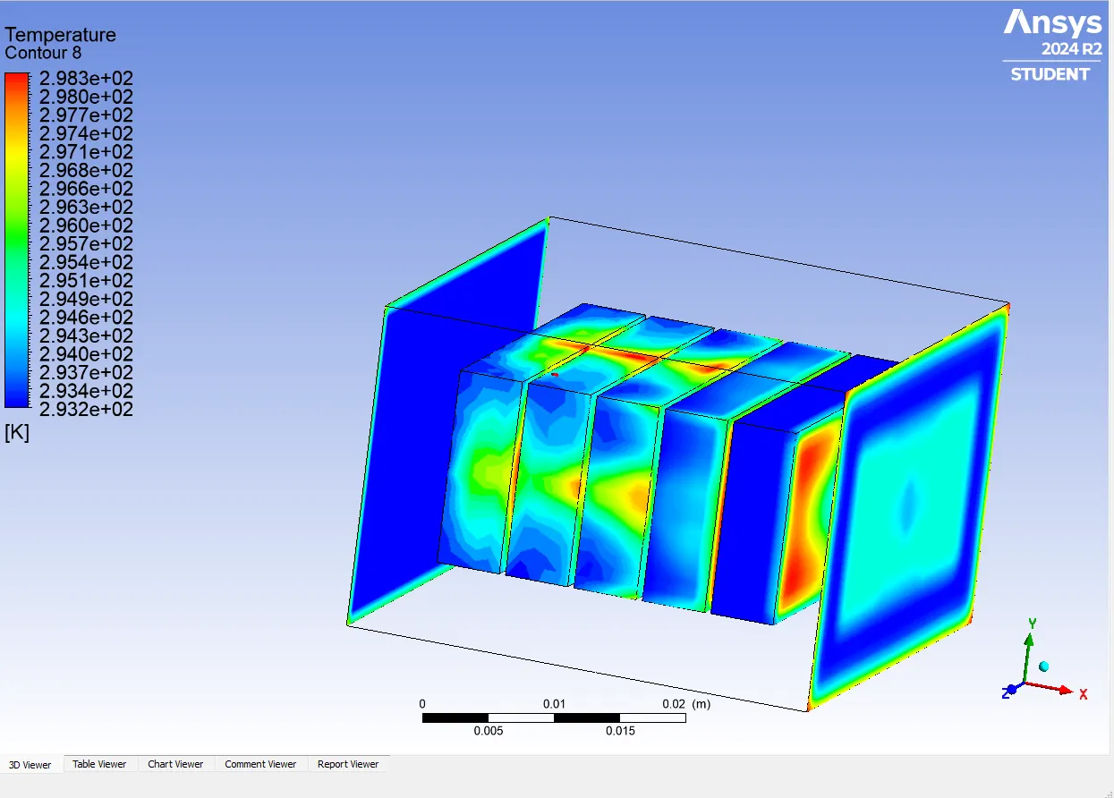
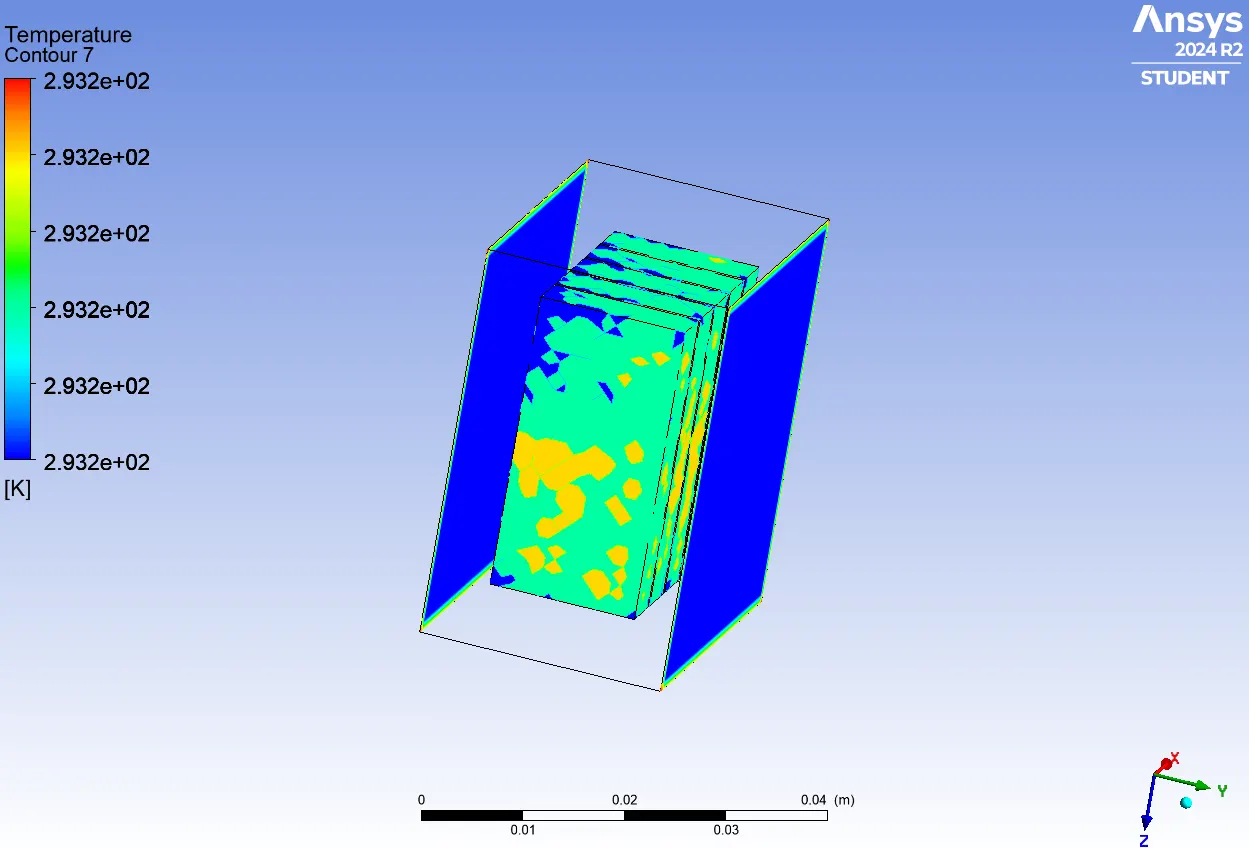
Inlet , outlet and Cells Temperatures :
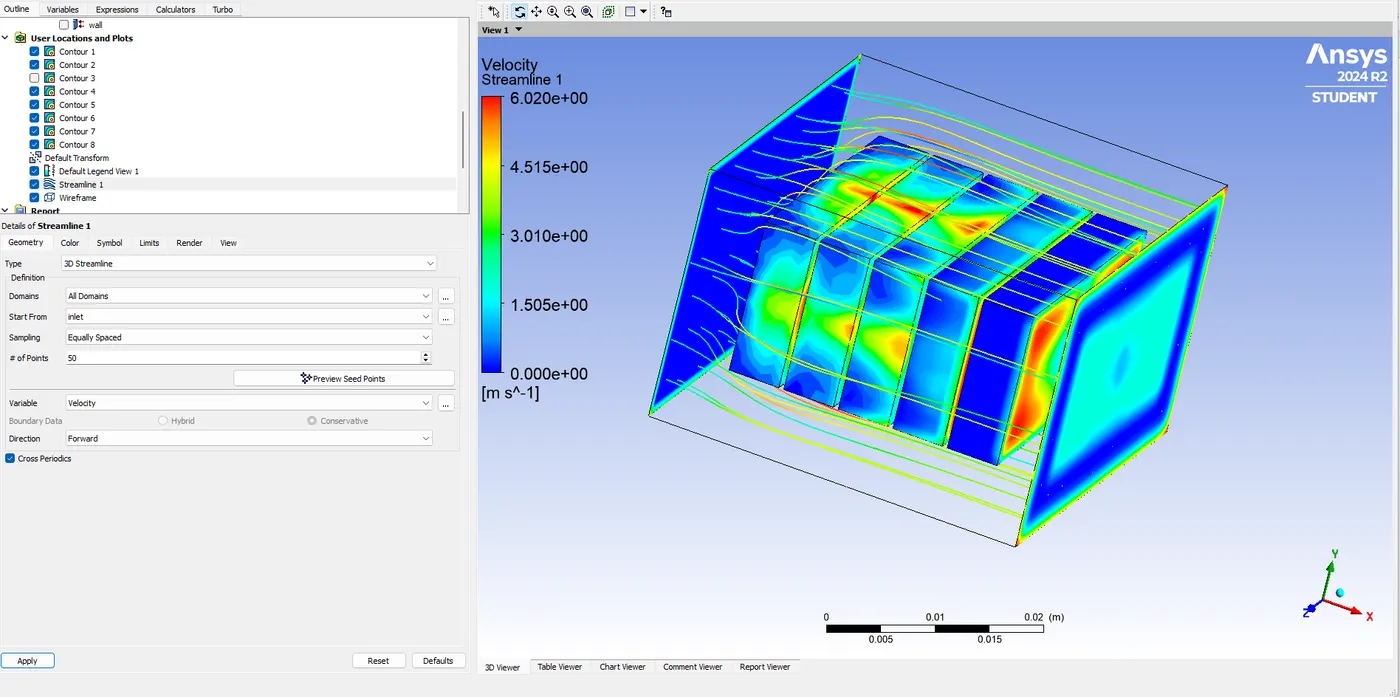
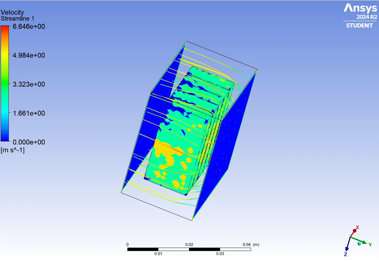
Air stream Lines :
2)Liquid Thermal Cooling System
Fluid: Liquid (Water)
Inlet: Velocity Inlet (2 m/s), Temperature = 20°C
Outlet: Pressure Outlet (0 Pa)
Energy Equation: Enabled
Viscous Model: k-epsilon
Heat Source: Applied to each cell as volumetric generation
Discharge Current
I=0.5*50=25 A
Heat Generated per Cell
Q = I2*R = 252*0.002 = 625*0.002=1.25 W
Volumetric Heat Generation (W/m³)
q = Q/Volume = 1.250 / 001053 ≈ 1187.9 W/m3.
Geometry and Boundary Conditions are similar .
For liquid cooling solid materials are similar to the air cooling only liquid material is added that is water .
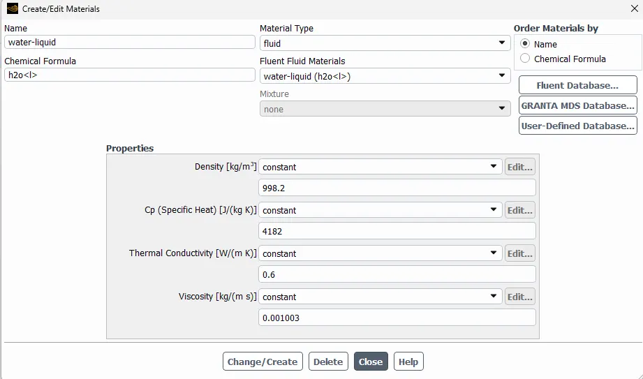
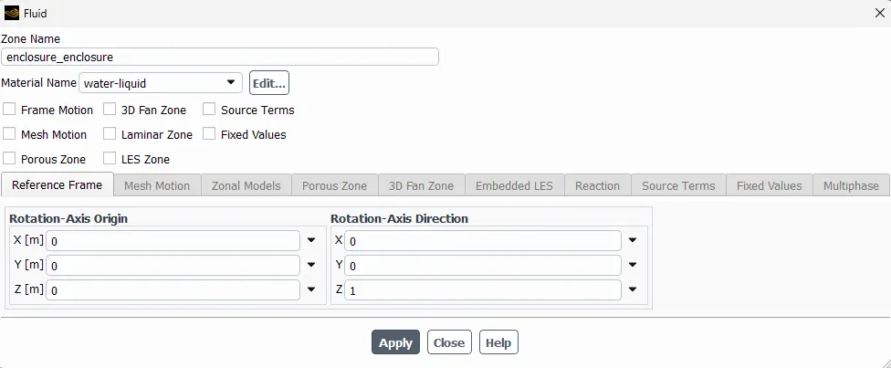
Cell zone conditions for cells are similar to the Air cooled system only enclosure is changes with water materials .
Solution methods are also similar to the Air cooled System.
Solution Results :
Temperature at wall :
Due to ambient Temperature of 45C degree Temperature condition, the wall is seen red in both cooling systems
Temperature at inlet, outlet and Cells.
Fluid Velocity Stream Lines :
Result Analysis for both cooling systems :
1)Air Cooling System - Results and Analysis
Temperature Range:
Min Temperature: ~293.2 K ≈ 20.0°C
Max Temperature: ~298.3 K ≈ 25.1°C
Key Observations:
Temperature Distribution:
Cells closer to the air inlet remain cooler (~20–22°C).
Cells further downstream show higher temperatures (~24–25°C), indicating reduced cooling effectiveness due to air heating up along the path.
Thermal Gradient:
A gradient of about 5°C is observed across the module.
Suggests non-uniform cooling, which can affect battery performance and cell aging.
Flow Path Influence:
The airflow is more effective at cooling surfaces directly facing the flow.
Internal cell faces (contact faces) remain warmer due to limited convective access.
System Performance:
Adequate for low to moderate loads, but may not suffice in high ambient or high-discharge conditions.
Improved performance may require higher airflow rates or additional ducting/baffles.
2)Liquid Cooling System - Results and Analysis
Temperature Range:
Min Temperature: ~293.2 K ≈ 20.0°C
Max Temperature: ~293.2 K ≈ 20.0°C
Observation:
The temperature scale is uniform, suggesting excellent thermal uniformity.
The entire system is nearly isothermal at 20°C.
Key Observations:
Temperature Uniformity:
The temperature contour shows no significant hotspots.
Indicates highly efficient heat extraction across all battery cells.
Cooling Effectiveness:
Liquid cooling maintains all cells at or very near the coolant inlet temperature (20°C).
Far superior to air cooling in terms of limiting thermal gradients and maximum cell temperature.
Thermal Management Advantage:
Reduces the risk of thermal runaway and improves battery longevity.
Better suited for high load or high ambient conditions where air cooling falls short.
Summary Table :
| Parameter | Air Cooling | Liquid Cooling |
|---|---|---|
| Temperature Range (K) | 293.2 – 298.3 | ~293.2 (Uniform) |
| Max Temperature (°C) | ~25.1 | ~20.0 |
| Temperature Gradient (ΔT, °C) | ~5.1 | <0.1 |
| Cooling Uniformity | Moderate to Poor | Excellent |
| Suitability for High Loads | Limited | Very High |
Conclusion :
The comparative analysis clearly demonstrates that liquid cooling offers superior thermal management performance over air cooling for battery modules. While air cooling resulted in a noticeable temperature gradient of approximately 5°C across the cells, the liquid cooling system maintained a nearly uniform temperature of ~20°C throughout the module. This thermal uniformity significantly reduces the risk of cell degradation, improves safety, and enhances the overall efficiency of the battery system. Therefore, for applications involving high current loads or elevated ambient temperatures, liquid cooling is the recommended solution for maintaining optimal battery health and performance.