Spare Wheel holder Discretization
Aim :
To perform the 2D shell meshing on the floor panel for the spare wheel
Objective :
Perform the geometrical clean up on the floor panel model followed by shell meshing using the stated quality criteria. After meshing the component, the thickness has to be assigned.
Target element length : 5mm
Introduction :
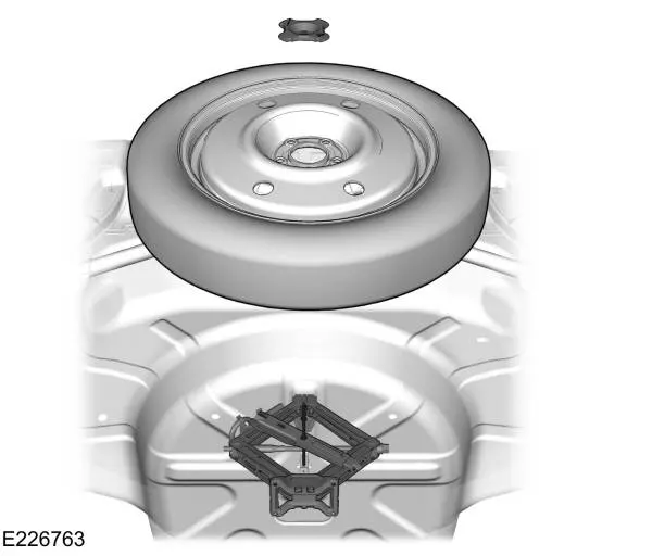
The floor panel is a large sheet metal stamping that often incorporates several smaller welded stampings to form the floor for the vehicle, here it includes the floor for the spare wheel of 4 wheelers.
The geometry of the floor panel for spare wheel changes from vehicles to vehicles i.e companies but they mostly a sheet metal component either punched or stamped to get the required shapes.
Most of the vehicles have this at the rear dickey side but some rare vehicles also have at the front side.
Procedure :
Step1: Importing the model into Hyperworks.
The Side door file is imported to HyperWorks workspace (file extension is .hm)
There are other types of file extension used in HyperWork
- IGES
The Acronym IGES stands for "Initial Graphics Exchange Specification".
IGES evolved from the U.S. Air Force's Integrated Computer Automated Manufacturing (ICAM) program in 1979. IGES was designed as a neutral format for the exchange of
CAD models and was first published in January 1980 by the U.S. National Bureau of Standards as NBSIR 80-1978. The file format can be shown as .igs, .ige or .iges.
- STEP
The Acronym STEP stands for "Standard for the Exchange of Product model data".
The development of STEP started in 1984 as a successor of IGES, but due to the complexity of the project, the initial standard was only published in 1994. The STEP format conforms to ISO 10303-21.
It is constantly updated, with the last major update in 2016. The file format can be shown as .step, .stp, .stpz, .ste or .p21
`file into the IGES format. When this file is shared, it is imported into the next CAD package and is translated again. File translations could potentially bring in inaccuracies in the geometry.
While STEP is a mature file format, it has been available for over 20 years with continual development and wide adoption between CAD vendors.
STEP is widely used and is even used in the construction industry, the IFC file format is a version of STEP.
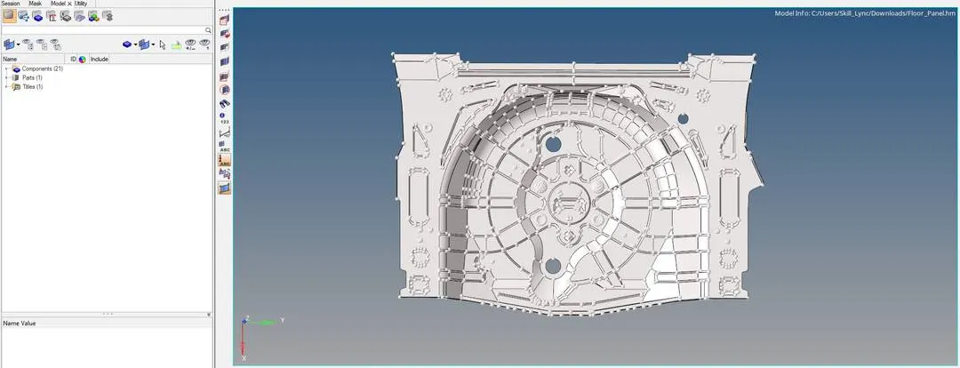
Fig-Floor panel imported into Hyperworks
Step 2: Cleaning up the geometry.
Geometry clean up means cleaning or preparing the geometry for the mid surface and meshing operation. Before extracting the mid surface the geometry has to be checked and cleaned from the following errors.
- Free edges
- Scar lines
- Duplicate surfaces
- Small fillets
- Small holes
- Beads
To check the geometry of any gaps and irregular or incomplete surfaces, it is better to switch to the wireframe mode. The advantage of the wireframe is that it only shows the edges or lines from which the surface is made off.
Green lines - two surfaces are joined
Red lines - free edges or single surface
Yellow lines - T connections of surfaces
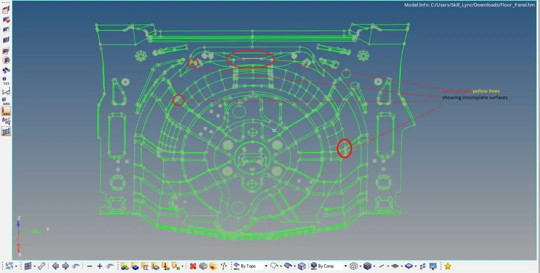
Fig- wireframe mode shows errors in surface
So the surface has to be checked for any free lines or red lines because while generating the mid surface it is important to make the geometry close for the proper mid surface.
Cleaning :
Here there are Yellow lines that mean there is a T connection or multiple/extra surfaces. To remove this error
- Go to geometry > quick edit > release points

- After that look for the extra surfaces and delete it. Tools > delete > surfaces
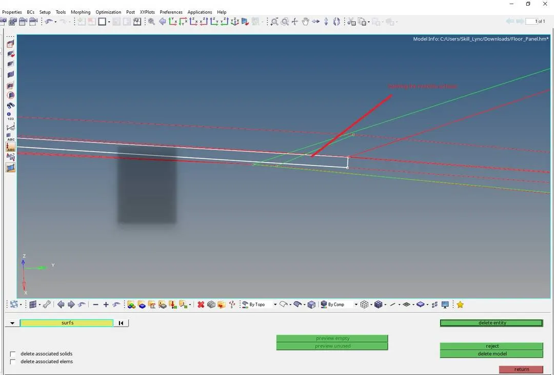
- Then join the two lines surfaces that are required. Quick edit > toggle

Like that most of the region can be patched with the help of toggle or replace points option.
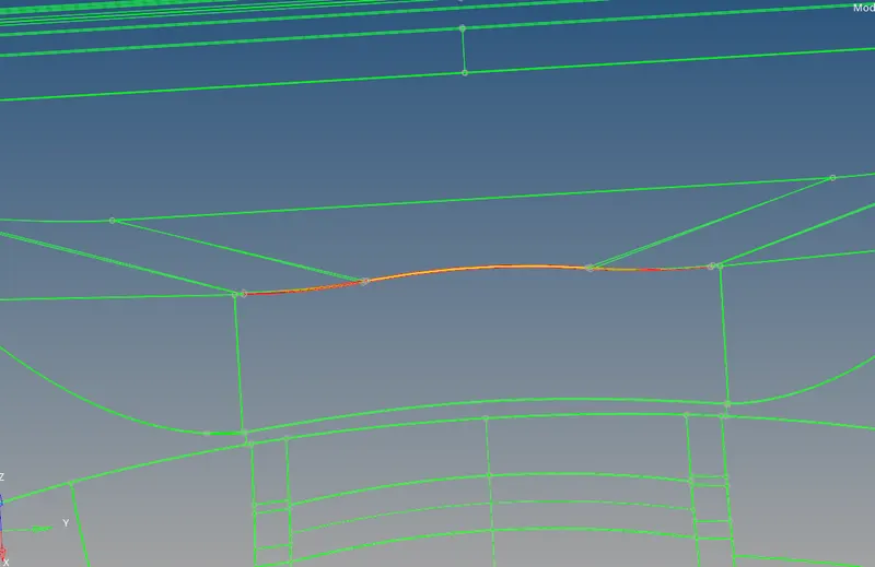
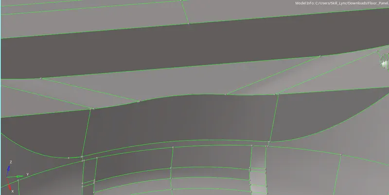
Step 3: Creating the mid surface
Before extracting the mid surface the model has to be reviewed or analyzed and measurement has to be carried to find the thickness of the geometry or features.
Tools > distance or F4 > two points
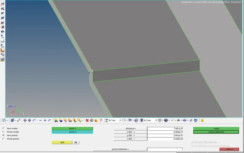
Fig- Measuring the thickness
Now the mid surface can be extracted by various methods two methods
- Offset / manual
- Auto mid surface
The auto mid surface extraction method is used in the conditions where the geometry is having a uniform thickness with fewer features or ribs. Though the thickness is varying here across the geometry the automatic mid surface can take care of that properly.
Geometry > mid surface > auto mid surface > surface

Step 4 : Assigning the quality criteria and topology cleanup for mid surface
The topology cleanup for the mid surface includes drawing and removing some construction lines in the regions to avoid the tria elements formations or to get the proper mesh flow.
Also, the geometry has to be checked for correctness by comparing it with the parent surface. It also includes removing the small beads or features that are too small for the minimum size of the elements.
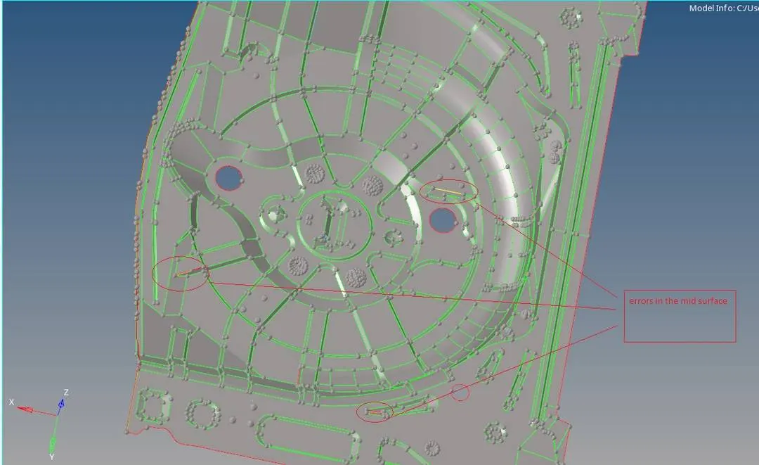
Fig- Obtained mid surface having geometric errors
Removing the beads :
There are certain small beads and features on the mid surface that are very small and cannot be captured even with small element size. So it is imperative to remove those beads from the surface to have a proper mesh flow with fewer elements failing in that region.
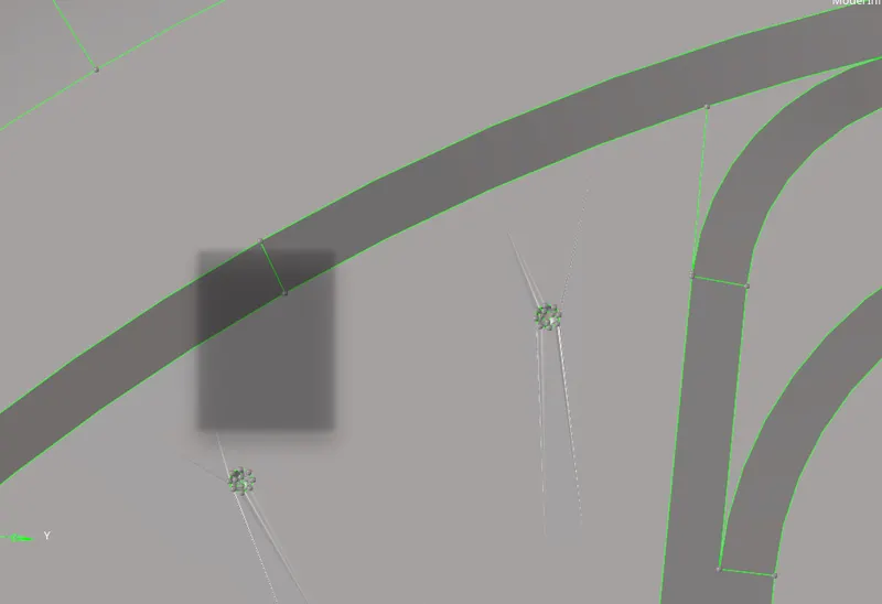
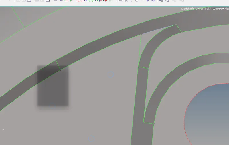
Fig- initial and final shows beads removed
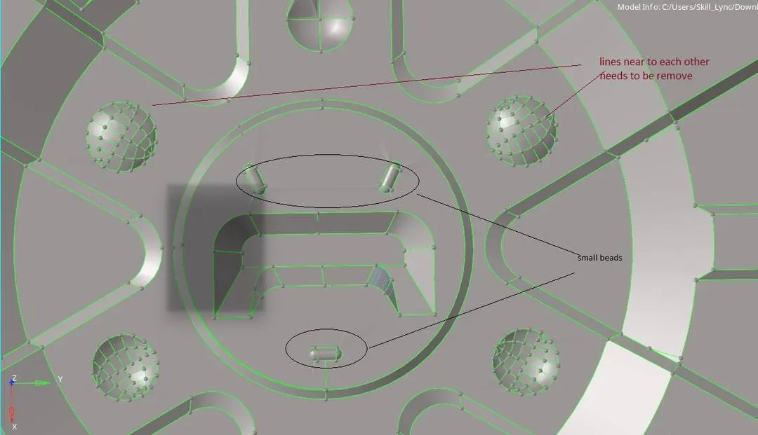
Fig - surface with beads and no geometric clean up
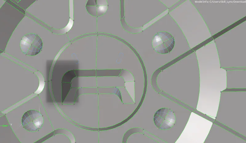
Fig- surface after geometric clean up
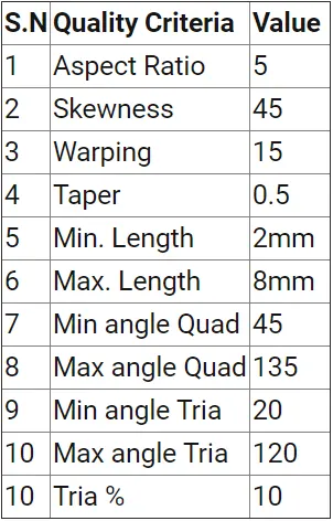
Quality criteria :
The quality criteria are followed before performing the mesh according to the requirement.
- Minimum and maximum length
Minimum as 2
Maximum as 8
This is to define the distance between two nodes over the surfaces. Any two nodes having distance less than 2 and greater than 8 will fail in element size
- Target length as 5
- Aspect Ratio- 3
The aspect ratio of a 2D element is defined as the ratio of its shortest edge length to its longest edge length. A square has an aspect ratio of 1 since its sides have the same length. As it gets away from the square shape, the aspect ratio becomes smaller than 1.
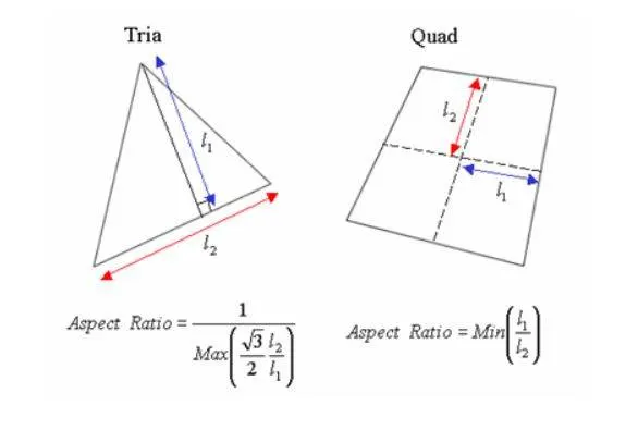
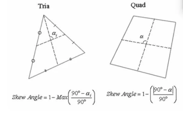
- Skew Angle- 45
An angle is formed by the two lines which pass through the midpoints of the sides of the quadrilateral. The skew angle represents the absolute value of the difference between the angle and 90 degrees. A rectangle has a skew angle of 0 since the formed angle between lines is 90 degrees.
For the triangle and quadrilateral elements, the skew angle is found as shown in the figure. For solid elements (Tetra, Hexa, Wedge), it calculates the skew angle for each element faces and assigns it with the minimum value.
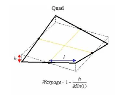
- Warpage-15
The warpage of the quadrilateral elements is defined as the deviation from a best-fit plane that contains the element. It is not always a case to define a plane with 4 nodes. Therefore, a node of the quadrilateral element may be formed outside of a plane.
The warpage is a measurement of how this node has deviated, and as it gets closer to 0, the element becomes more planar. For the quadrilateral elements, the warpage is found as shown in the figure. For solid elements (Hexa, Wedge), it calculates the warpage for each element faces and assigns it with the maximum value.
All the values for the quality criteria have to be fed before starting the meshing. To do that go
Menu bar >preferences > criteria file settings
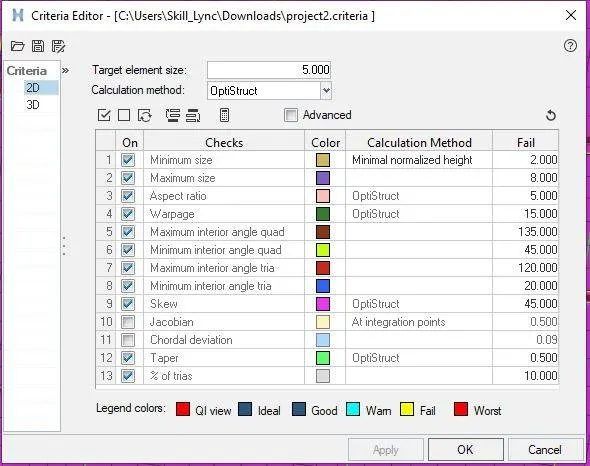
Fig- Criteria file settings
Step 5 : Performing the 2D meshing
Perform the meshing keeping in mind that no rotating quads and no opposite tria element Rectifying the errors of mesh. For convenience, we switch on the view mode to by element quality that shows the number of elements failing the criteria.
The meshing is approached by doing manually region-wise using the construction lines that were created to help in getting the proper mesh flow with less tria concentration.
Reflect :
The geometry is somewhat identical and symmetric in most of the region, so we can save time for meshing by using the reflect elements option to get the other half of meshing in a little time.
To do that
- Go to Tools > reflect > elements

- Select the elements. Go to Elements> duplicate. The selected elements need to be duplicated first to reflect them.
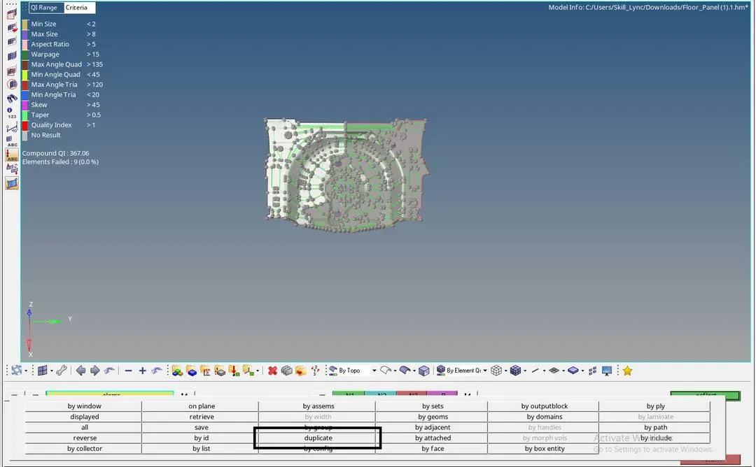
- Then press Reflect > return
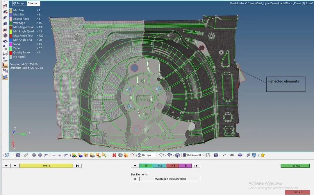
- Now to attach or connect the reflected elements go to Tools > edges > elements

- Change the tolerance to 0.5 and Preview equivalence. It will display the nodes in yellow colour that need to be attached. Press Equivalence.
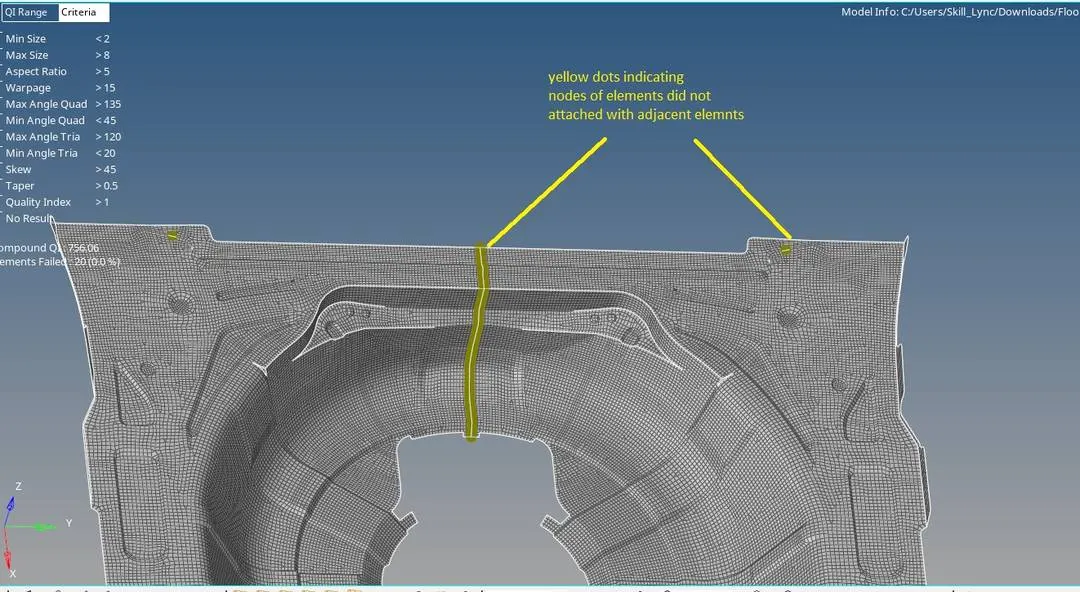
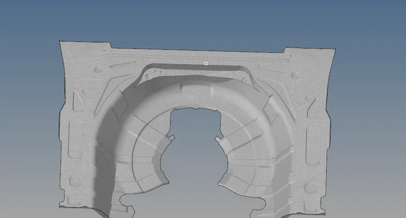
Fig- all the elements are attached
Rectifying the errors :
- Warpage errors: these errors are shown in green colour here and occur in quad elements. To remove these errors we use the translate option to orient the element properly.
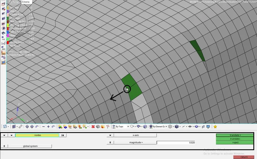
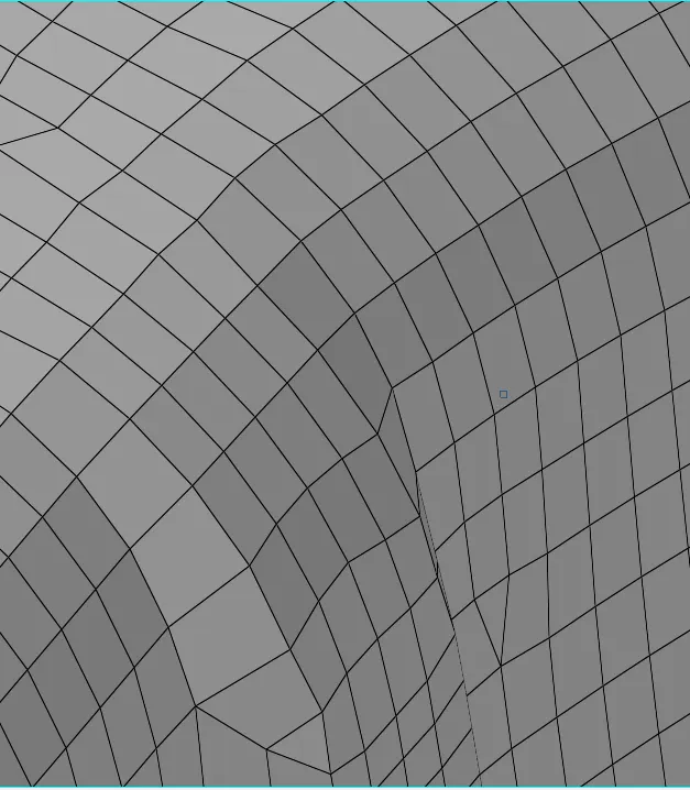
Fig- warpage error fixed
- Min and max length error: these errors arise when the element does set into a defined value. To rectify these use the distance option to change the distance or length of the elements.
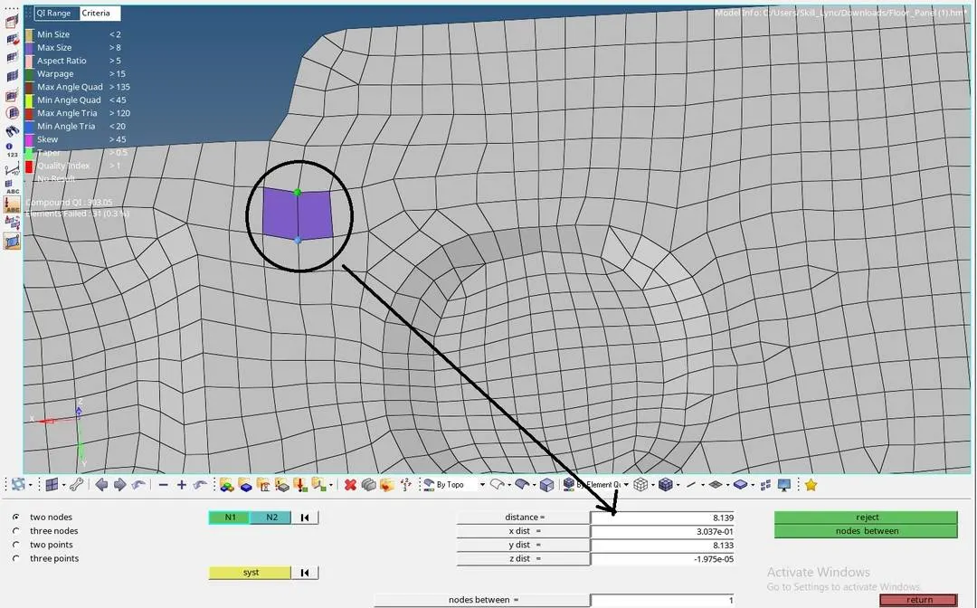
Fig- distance is greater than max element length
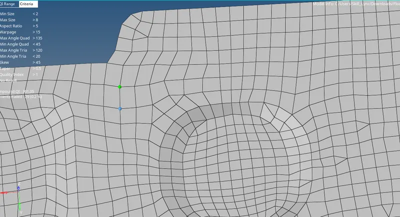
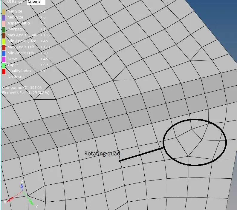
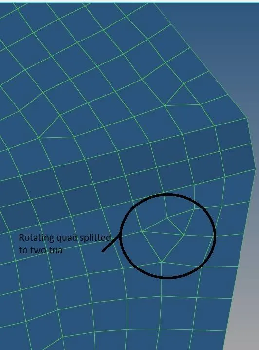
Rotating quads: to rectify the rotating quads use the split option, split the quad into trai .
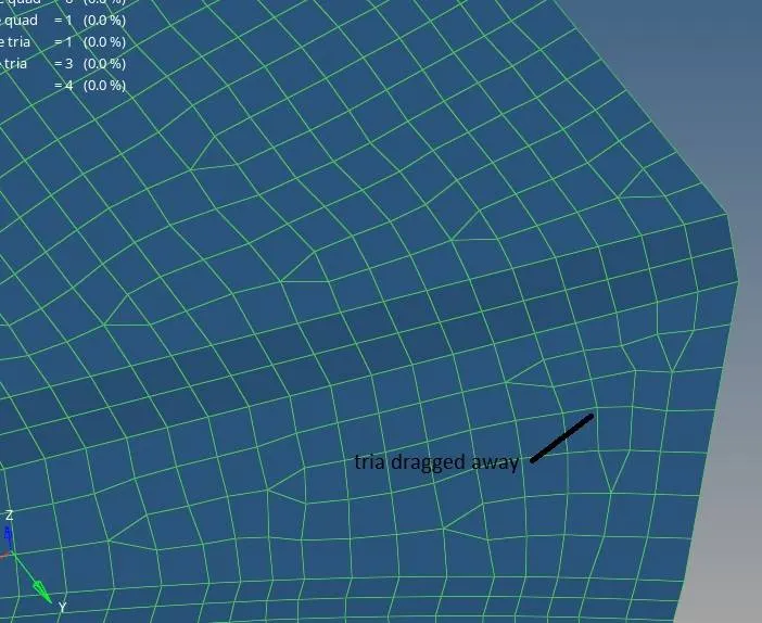
Opposite tria : these can be eliminated by using the drag option and joining them as one present near each other also with proper mesh flow.
Using all the above tools the meshing is performed with proper mesh flow and no failed elements.
Step 6: Assigning the thickness
The final mesh obtained had to be assigned with the thickness value. To do that we will use the automatic thickness method since the thickness is varying in the surface and this method will assign the thickness accurately by measuring the thickness with the parent surface. The steps are as follows
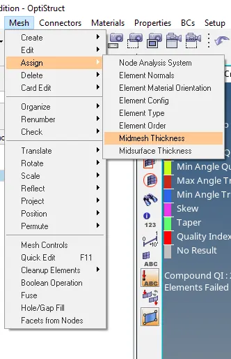
- Go to mesh>assign > mid mesh thickness from the Menu bar as shown below
- Now a window opens map mid mesh thickness- optistruct .
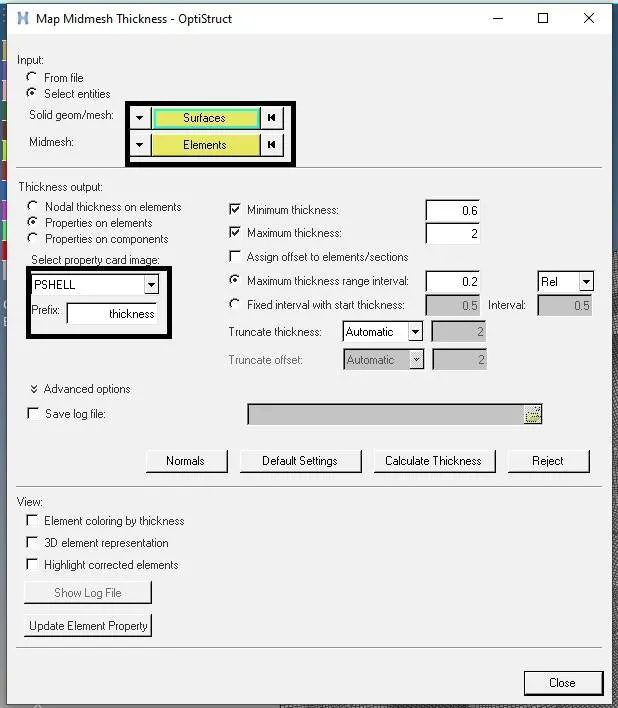
- Go to select entities > surfaces - select the surface as the parent geometry
- Go to elements >select the elements as the elements for the mid surface
- Go to thickness output > properties on elements. By selecting this option it will create a new Property based on the thickness calculated from the parent geometry and that will be automatically assigned to 2D shell mesh. Now in the prefix option it can be changed to any name we want for the property name.
- Then press the calculate thickness
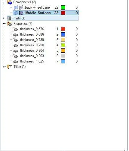
Fig- Properties created by the automatic thickness
Result:

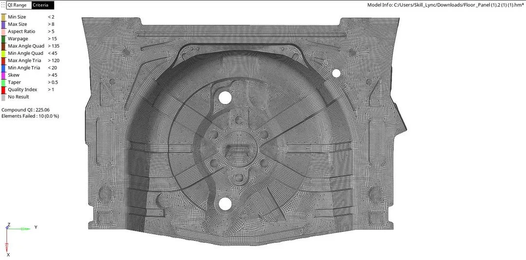
Fig- 2D mesh for Floor panel
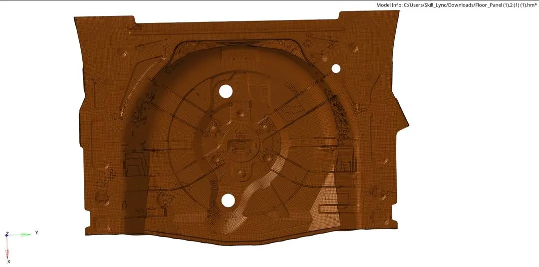
Fig- Thickness enabled for Floor panel
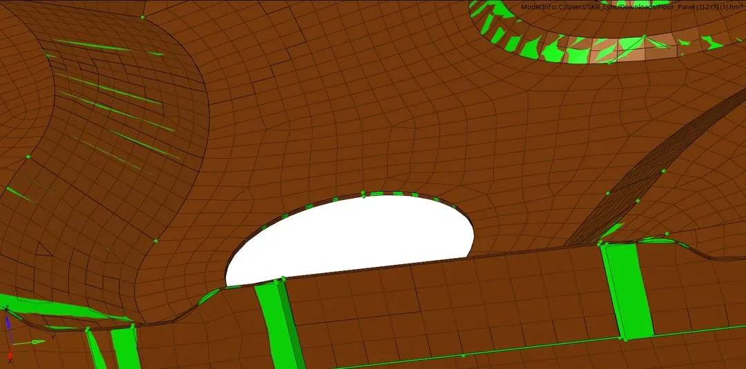
Fig- Comparing the 2D mesh thickened with parent surface
Conclusion :
The floor panel for the spare wheel mid surface is extracted properly followed by the meshing. All the process except for meshing was carried out using the automatic method.
There are some failed elements in the final mesh at the very narrow converging section which can be resolved if we can compromise with the feature capturing.
References :
https://skill-lync.com/knowledgebase/automatic-thickness-in-hypermesh
https://www.cadlinecommunity.co.uk/hc/en-us/articles/115000846485-STEP-Files-vs-IGES-Files