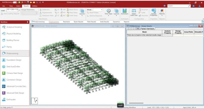
Project 2
Aim- to model and design a proposed PEB warehouse using STAAD.Pro
Introduction- Here we model and design the PEB warehouse buidling.As per given description,material data,specification we can design it.
- PEB- Pre engineered buildings are factory built buildings shipped to site and assembled by bolting together.
- The columns and beams are custom fabricated I sections with end plate and holes for bolting at both ends.
- I sections are made by cutting steel plates of desired thickness and welding them together.
- Engineering is done specifically for that buildig to satisfy structural and asthetic requirements.
- To optimize the structural efficiency the shape of beams can be tailored.
Procedure:
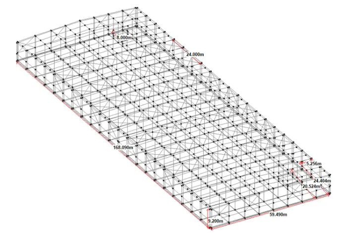
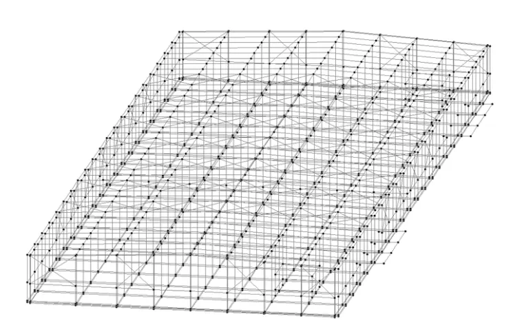
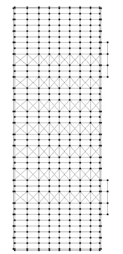
- Open Staad>then define nodes and beams as per given data> draw beams and columns > draw bracings, purlins,girts,walls and canopy.
- Complete the model of pre engineered building structure.
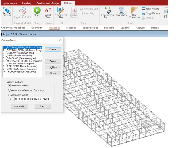
To create groups for assign of properties and loads.
Go to utilities > groups > create groups as per names and select the section of structure.
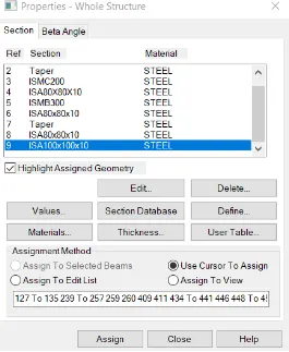
Go to properties > define and assign the property to structure.
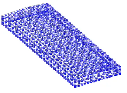
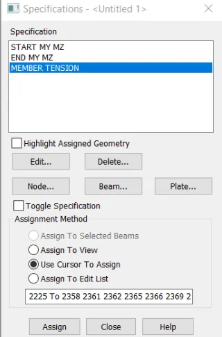
Go to specification > add specification to member of strcuture.
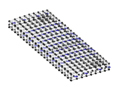
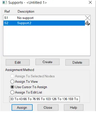
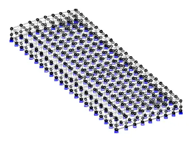
Go to supports > create support as fixed support
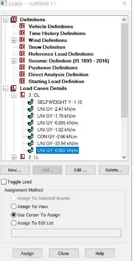
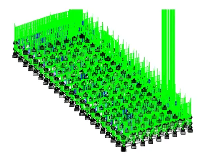
Go to loading > add and assign loads as dead,live and wind load.
Self weight on purlins= 10 Kg/m^2=0.1 Kn/m^2
=0.1 x 0.845+ 0.1 x 8= 1.60 Kn/m
Self weight on portals= 15 Kg/m^2= 0.15 Kn/m^2
=0.15 x 0.845 + 0.15 x 8=2.41 Kn/m
Assumed weight of purlin= 100x100x10=14.9 Kg/m
Udl load due to purlin over the main frame=(no of purlin x weight of purlin per m)/ rafter length
No of purlin= round off(Rafter length/Purlin Spacing)+1
= round off(31.34/8.916)+1
=5
Udl due to purlin over main rafter=5 x 8 x 14.9 x=596/31.34= 19.0 Kg/m=0.19 Kn/m
Total udl on main rafter= 1.6+0.19=1.79 Kn/m
Total udl on roof on gable rafter =1.79/2=0.895 Kn/m
Weight of side wall sheet= 5Kg/m^2=5 x 8.045 +5 x 8 =80.225 Kg/m= 0.802 Kn/m
Weight of sag rods and bracing= 5 Kg/m^2=0.82 kn/m
Weight of girts=22.1 Kg/m=0.221 Kn/m
Total weight of girts=0.221+0.802=1.02 Kn/m
Assumed weight of eave strut=10.7 Kg/m
Weight of eave strut= 5.89 kgm
Load due to eave gutter and eave strut= 10.7+5.89=16.59 Kg
=16.59 x 8.045 + 16.59 x 8=266.18 Kg=2.66 KN
Self weight of RCC slab 150mm thick for mexxanine= 25x0.5x7.2=27 Kn/m
Density of concrete=25 Kn/m^3
Self weight of structural member for mezzanine=44.2 Kg/m=0.442 Kn/m
Floor finish load for mezzanine=150 kg/m^2=1.5 Kn/m
Addition load for mezzanine = 500 Kg/m^2= 5Kn/m
Total load on mezzamine floor =27+0.442+1.5+5=33.94 Kn/m
Live load-
On roof and canopy=57 Kg/m^2=57 x 8.045 + 57 x 8= 914.56 Kg/m= 9.14 kn/m
On gable rafter =9.14/2=4.57 Kn/m
on mezzanine floor=400 kg/m^2=400 x 8.045 + 400 x 8= 64.18 Kn/m
Assume eave gutter size=250 x 250 x 1 mm =0.25 x 0.25 x 10= 0.625 Kn/m
On main column=0.625 x 8.045 + 0.625 x 8= 10 Kn
On gable column= 10/2= 5 KN
Collateral load
Due to electric fittings= 10 Kg/m^2= 10 x 8.045 + 10 x 8=160.45 Kg/m
Due to electric fittings= 1.6 Kn/m
Due to Sprinklars and fire fighting system= 3 Kg/m= 3 x 8.045+ 3 x 8 =48.135 Kg
Due to Sprinklars and fire fighting systen = 3 Kg/m= 3 x 8.045 + 3 x 8= 48.135 Kg
Due to sprinklars and fire fighting system= 0.481 Kn
Load due to insulation= 10 Kg/m^2 and 5 Kg/m^2= 10 x 8.045+ 10 x 8=160.45 Kg/m
=5 x 8.045+5 x 8= 80.225 Kg/m = 0.80 kn/m
total load due to insulation=1.6+0.80=2.4 Kn/m
Load due to solar panels=15 Kg/m^2=15 x 8.045 + 15 x 8 = 240.67 Kg/m
Load due to solar panels=2.4 Kn/m
load due to false ceiling support= 10 Kg/m^2=1.6 kn/m
tital load=1.6+2.4+2.4+1.6=8 kN/m
Seismic load
Member weight
Live load=9.14 x 0.25=2.285 Kn/m
Collateral load=8 x 1= 8Kn/m
Dead load= 1.79 x 1=1.79 Kn/m
Live load + Collateral load= (9.14+8) x 0.5=8.57 Kn/m
Wind load-
Basic wind speed Vb=39 m/s
K1=1.00
K2=1.05
K3=1.00
K4=1.00
Coefficient of cyclonic wind=1.0
Kd=0.9
Ka(Rafter)=0.8
Ka(column)=0.8245
Ka(purlin)=0.9721
Ka(side runner)=0.978
Area averaging factor=(0.8+0.8245+0.9721+0.978)/4=0.89
Kc=0.9
Cpi=+/-0.2
Design wind speed=Vb x K1 x K2 x K3 X K4
=39 x 1.0 x 1.05 x 1.0 x 1.0=40.95 m/s
Wind pressure=0.6 x 40.95^2=1.00 Kn/m^2
Design wind pressure=1 x 0.9 x 0.89 x 0.9=0.72 Kn/m^2
External pressure coefficient(Cpe) for roof=IS 875 part 3
0 degree EF = -0.9
0 degree GH=-0.4
90 degree EG= -0.8
90 degree FH=-0.4
External pressure coefficient(Cpe) for column=
Degree A B C D
0 0.7 -0.25 -0.6 -0.6
90 -0.5 -0.5 0.7 -0.2
Use Cpe-Cpi
WL -0+CPI-
Load on EF=(-0.9-0.2) x 0.72 x 8.045 + (-0.9-0.2) x 0.72 x 8=-12.70 Kn/m
Load on GH=(-0.4-0.2) x 0.72 x 8.045 + (-0.4-0.2) x 0.72 x 8=-6.93 Kn/m
Load on Column A=(0.7-0.2) x 0.72 x 8.045 + (0.7-0.2) x 0.72 x 8=5.77 Kn/m
Load on Column B=(-0.25-0.2) x 0.72 x 8.045 + (-0.25-0.2) x 0.72 x 8=5.198 Kn/m
WI -90+CPi-
Load on EG=(-0.8-0.2) x 0.72 x 8.045 + (-0.8-0.2) x 0.72 x 8=-11.55 Kn/m
Load on FH=(-0.4-0.2) x 0.72 x 8.045 + (-0.4-0.2) x 0.72 x 8=-6.93 Kn/m
Load on Column A=(-0.5-0.2) x 0.72 x 8.045 + (-0.5-0.2) x 0.72 x 8=8.082Kn/m
Load on Column B=(-0.5-0.2) x 0.72 x 8.045 + (-0.5-0.2) x 0.72 x 8=8.082 Kn/m
WI -90-CPI-
Load on EG=(-0.8+0.2) x 0.72 x 8.045 + (-0.8+0.2) x 0.72 x 8=-6.93 Kn/m
Load on FH=(-0.4+0.2) x 0.72 x 8.045 + (-0.4+0.2) x 0.72 x 8=-2.31 Kn/m
Load on Column A=(-0.5+0.2) x 0.72 x 8.045 + (-0.5+0.2) x 0.72 x 8=3.465Kn/m
Load on Column A=(-0.5+0.2) x 0.72 x 8.045 + (-0.5+0.2) x 0.72 x 8=3.465Kn/m
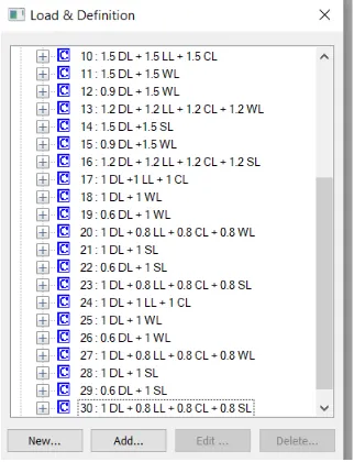
Go to loading > add load combination case
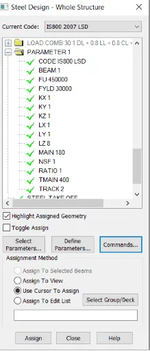
Go to design > select codes > define and assign the design parameters.
Go to analysis > run the nalysis > check results