Project 2
MESHING AND CONNECTION OF REAR SUSPENSION ASSEMBLY IN ANSA
The suspension system of a vehicle refers to the group of mechanical components that connect the wheels to the frame or body. One of the most popular suspension system used in passenger car is the independent suspension with coil springs. It is both cheap and considerably reliable in terms of failure frequency.
The basic components of a suspension system are as follows: -
CONTROL ARM: A movable lever that fastens the steering knuckle to the vehicle frame or body.
BUSHING: A sleeve, which allows the control arm to move up and down on the frame.
STRUT ROD: It prevents the control arm from swinging to the front or rear of the vehicle.
BALL JOINTS: A swivel joint that allows the control arm and steering knuckle to move up and down, as well as side to side.
SHOCK ABSORBER or STRUT: keeps the suspension from continuing to bounce after spring compression and extension.
STABILIZER BAR: limits body roll of the vehicle during cornering.
SPRING: supports the weight of the vehicle; permits the control arm and wheel to move up and down.
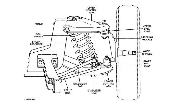
FIG: Independent suspension
OBJECTIVE: -
- Geometry cleanup and geometry check for Automotive Rear-suspension assembly.
- Thickness measurement of various parts and choose appropriate technique to mesh the component.
- Fix the failed elements to improve the quality of the mesh.
- Perform volumetric mesh for parts with provided quality criteria
- Apply appropriate connections between two components wherever required.
PROCEDURE: -
- Open the "Rear Suspension.ansa" file from the File>Open command.
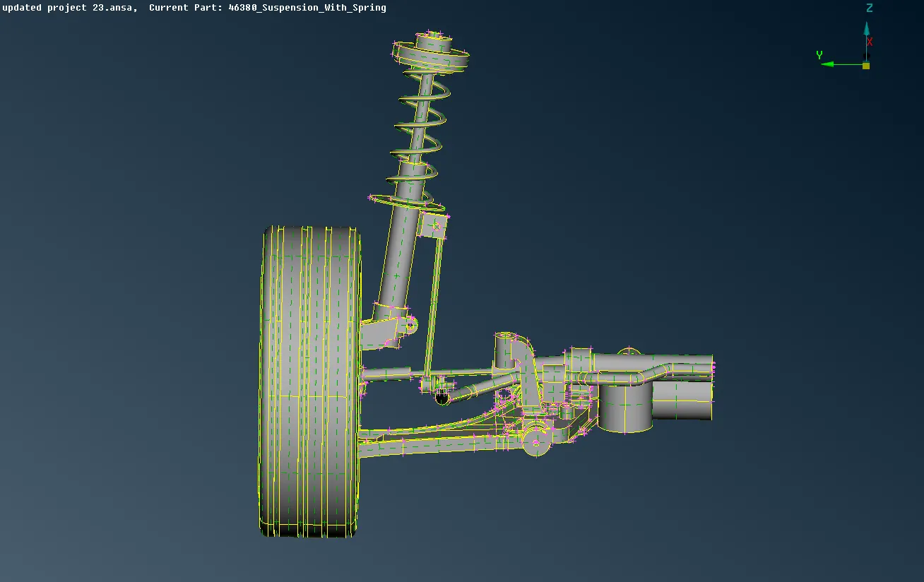
FIG: Intially imported model
- Check the geometry for any kind of error and remove them for a proper midsurface extraction. Go to Tools>Check>Geometry>Execute and a list of errors will show up, we can fix the errors by right mouse click and choose automatic fix. Some errors may need to be fixed manually.
- The suspension system consist of different parts with variable thickness across the cross section. If the thickness of the part is less than 5mm we will mesh the component with shell mesh and otherwise we will go with the volume mesh.
- Select V.Mesh>Define>Auto detect to define the volume. Click on V.mesh>Volumes>list to see the full list of component we can mesh with v.mesh. Click right mouse button on part and select Remesh.
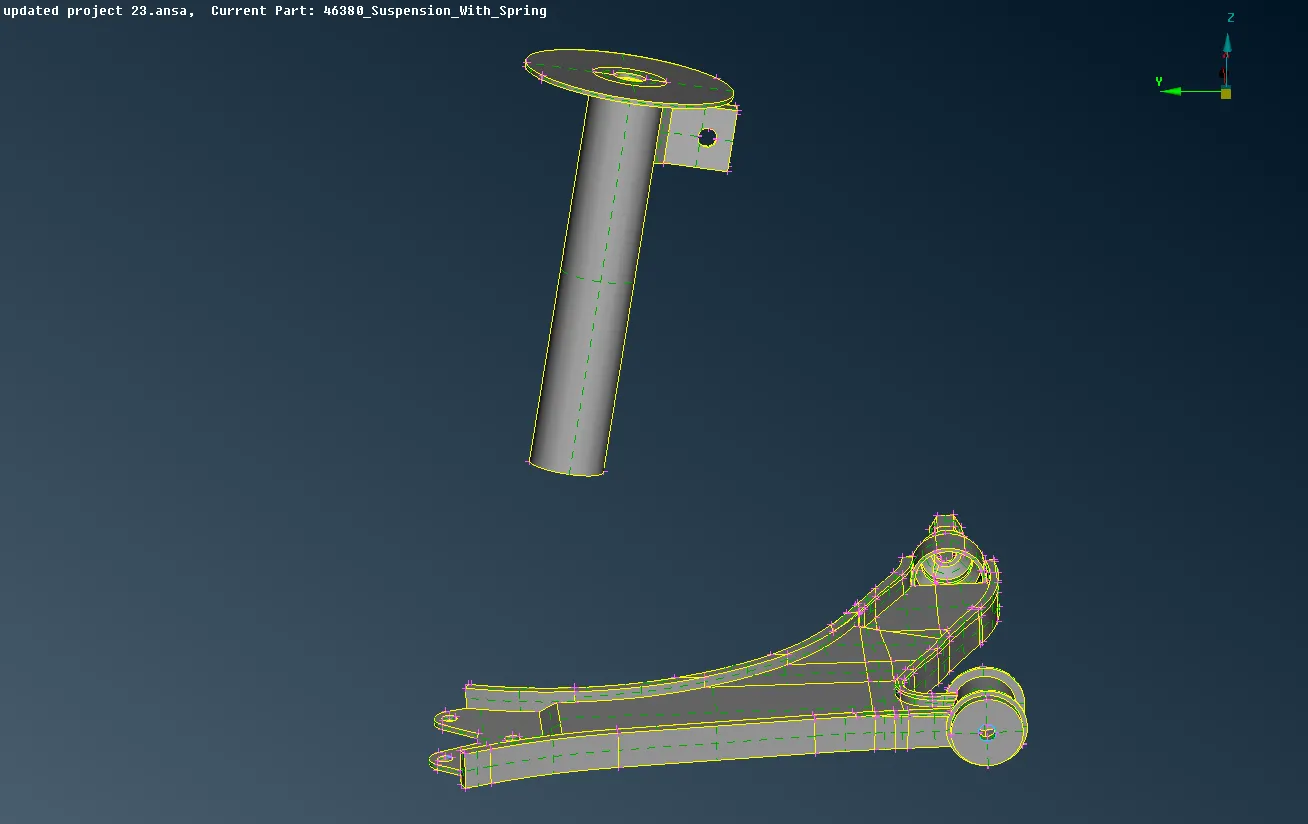
FIG: Meshing carried out using mid surface meshing
- Control arm is meshed with shell mesh as the thickness is less. Activate Topo>Faces>Offset to offset the macro.
- Go to Topo>Faces>Set PID and assign the surfaces to different PID's according to their thickness. Click Lists>Properties and we can see all the properties which are being created.
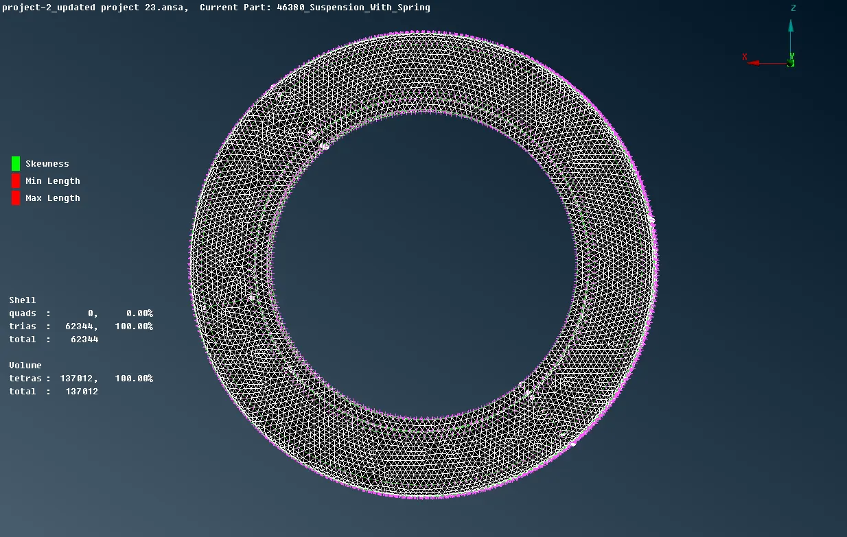
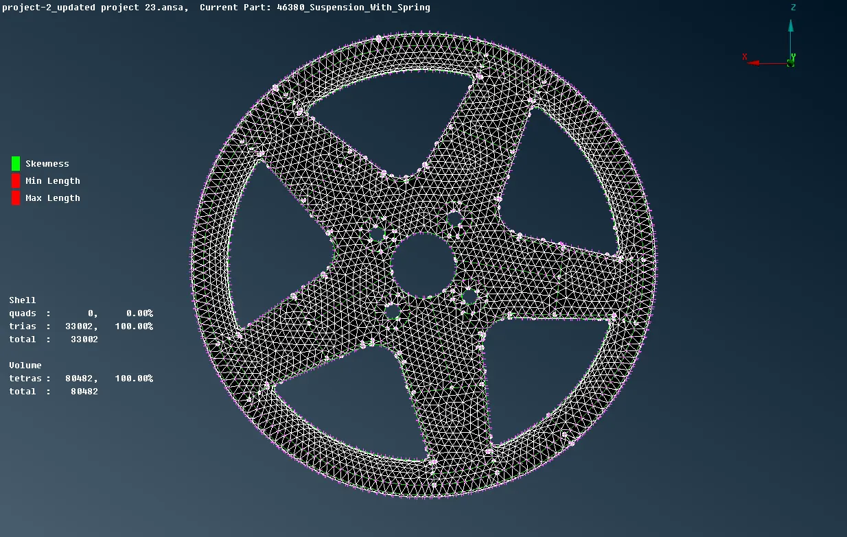
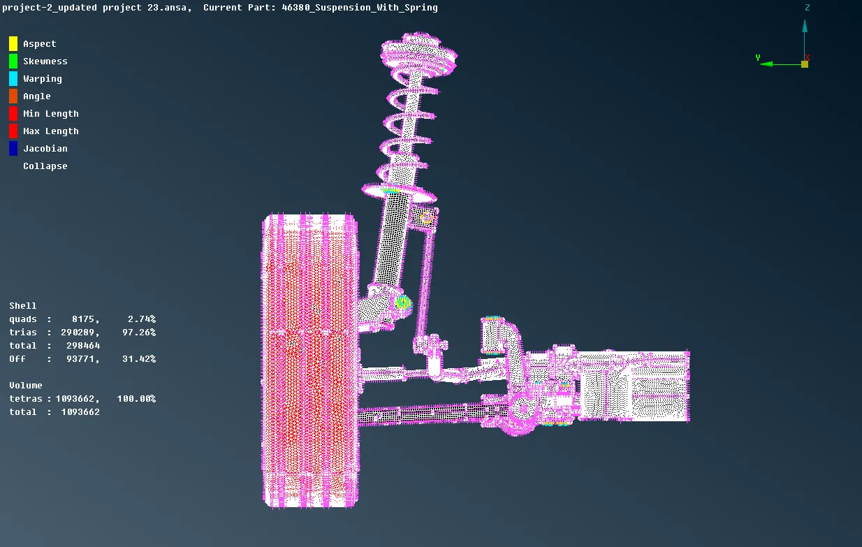
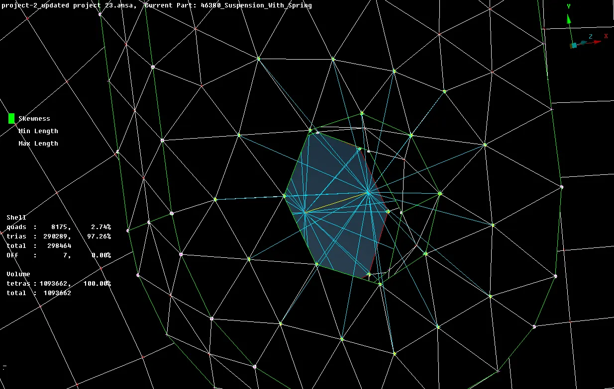
- In order to represent a bolt connection a many node RBE2 is used. Activate Nastran deck>RBE2>Many nodes and select elements, press middle mouse button to create master node.
- Use FEAT2CURVE tool to create a feature curve, convert it to seam weld line and create a seamweld connection in appropriate places.
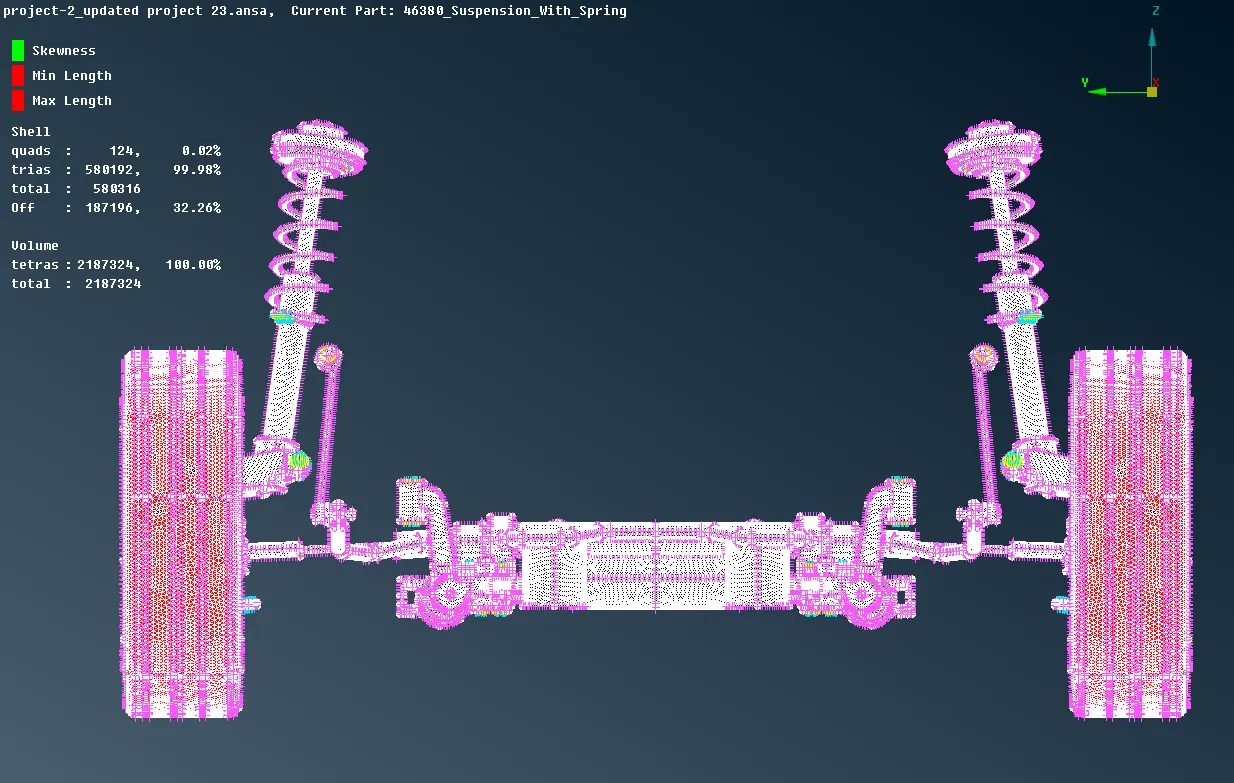
- Perform symmetry using Utilities>Transform>Copy>Symmetry. Make a window to select the whole geometry and specify three points and press middle mouse button to perform symmetry
CONCLUSION: -
The Suspension system is meshed with V.Mesh and shell mesh and all the tet collapse element is solved in order to get an improved mesh quality.
Appropriate connections are applied to repesent the connectivity between various parts.